8
9
13
21
28
43
63
66
25
37
8
17
54 58
12
15
23
31
48 53
0
0
50
25 50 75 100 125 150 175 200
100
150
200
250
300
Safety instructions
If the dwelling contains combustion equipment
(tiled stoves, fire places, wall mounted gas
heaters, etc.), ensure that such combustion
equipment is supplied with combustion
air separate from the ventilation system
(check with your local flue gas inspector,
as requirements vary across regions and
countries).
When operating a dryer or a cooker hood
that extracts air, ensure also, that a sufficiently
large air volume flow is supplied to that
equipment, independent of the ventilation
equipment.
2.4 Electrical connection
The equipment is supplied fully wired, and
should be plugged into an accessible mains
power socket.
A 1 m long LV cable for the connection of a
remote control is supplied with the device.
Observe VDE 0100 [or local regulations] and
the regulations of your local power supply
utility.
2.4.1 Remote control unit FEZ II
The FEZ II remote control enables the
selection of one of the three preset air flow
rate stages.
The operating mode selector offers the
functions: party, day/night, automatic and
standby (OFF).The programmable analog
time switch controls the changeover between
day and night mode. An indicator signals the
requirement for changing the air filter.
2.4.1 Remote control FEQ (part no: 189800)
The FEQ remote control enables the selection
of the three preset air flow rate stages.
The operating mode selector offers the
functions: party, standard/setback mode,
automatic and standby (OFF).
2.3 Installation on the air
side
The installation is completed with
commercially available slip tubing and profiles.
This installation material may be obtained
from Stiebel Eltron.
During the installation, ensure that no metal
swarf enters the pipe system. However, should
this occur, remove this debris, otherwise the
fans may be damaged.
Thermally insulate these pipelines, if they are
constructed from non-insulated pipes and
profiles.
Where the ventilation air and extract air ducts
are routed through unheated rooms, thermally
insulate those too.
Please note: Never connect cooker
hoods and dryers to the ventilation
system.
Silencers
Generally, fit one silencer each in the
ventilation air and the extract air duct.
Additional silencers are recommended
upstream of bedrooms and living rooms (or in
rooms where noise should be kept down and
where noise transmission should be avoided).
If a room with a high noise level must be
ventilated, install additional silencers in the
approach to and the exit from such rooms
to reduce sound transmission into adjacent
rooms.
Clean-out apertures
Air ducts must be checked and possibly
cleaned at regular intervals. Releasing the air
duct from the device or at the extract air and
ventilation air valves enables the inspection
and cleaning.
External wall outlet
Supply fresh air from a location where
contamination (dust, soot, odours, flue gas,
expelled air) is as low as possible.
When creating the external wall outlet ensure,
that a “short circuit” between the fresh air
inlet and air outlets is avoided. It would be
practical to use our external wall inlet and
outlet grille (part no: 07 18 32).
Ventilation and extract air valves
Ventilation and extract air valves for the living
space are available for wall or ceiling mounting.
During installation, ensure a thorough
ventilation of the room.
Overflow apertures
The living rooms and bedrooms only
receive air, and the rooms loaded with
odour and humidity only have air extracted.
Consequently, fit interconnecting ventilation
grilles into adjoining doors or walls or increase
the air gap below a door to ≥8 mm, to
ensure an unrestricted air flow between
rooms.
2.4.2 Three-stage switch (part no: 162551)
The three-stage switch enables the selection
of the three preset air flow rate stages.
The operating mode selector offers the
functions: party, day and night mode.
2.4.3 Installation of remote control units
Connect the respective remote control,
subject to the equipment-specific operating
and installation instructions or in line with
the connection diagram on page 9, to the
equipment using the device interface and the
connecting cable supplied.
Please note: Route the LV cable of
the remote control units and the
power supply cable of the ventilation
device separately.
2.5 Frost protection
The frost monitoring ensures that the extract
side of the heat exchanger cannot freeze
up.This is achieved by the ventilation air
flow and the extract air flow being brought
out of balance, subject to the outside air
temperature and the pressure at the heat
exchanger.
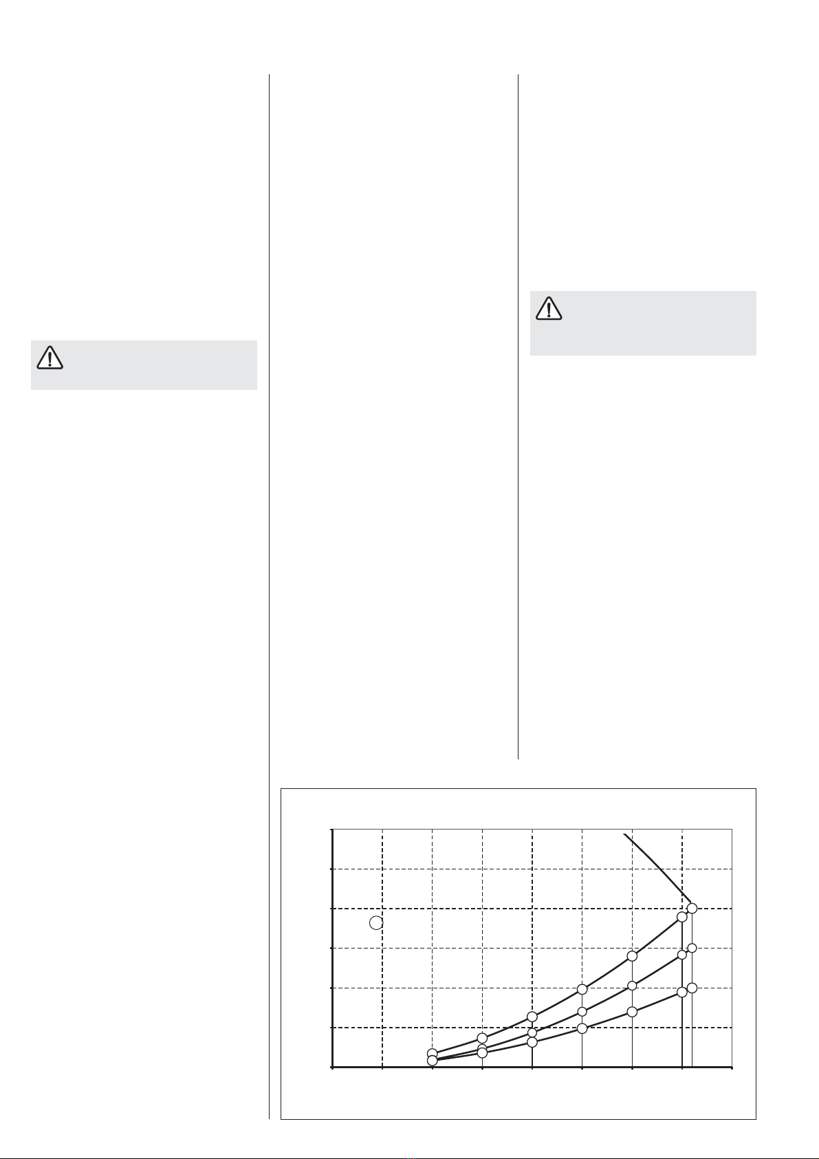
Fan curve LWZ 70
26_04_01_0202
X Power consumption per fan [W]
Air volume [m³/h]
Static pressure [Pa]