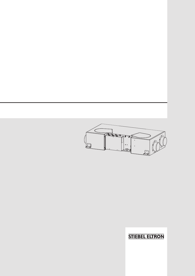
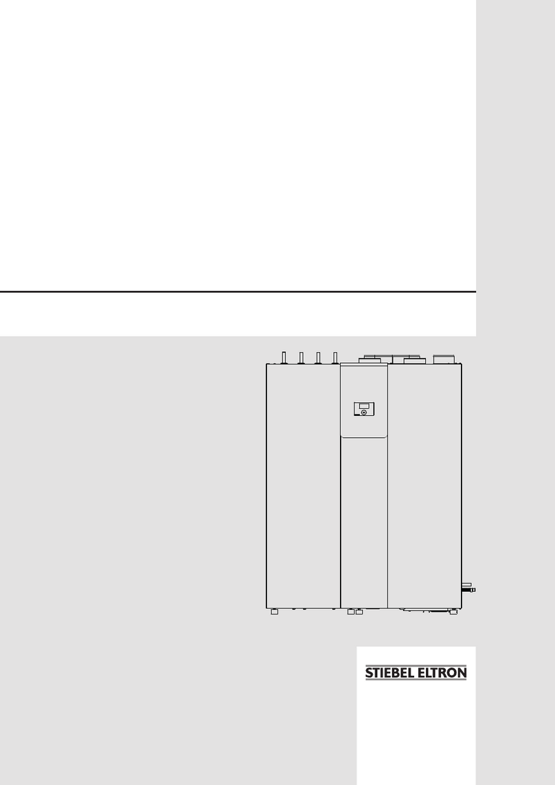
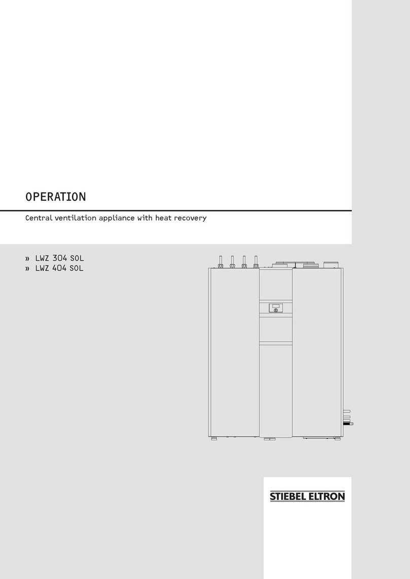
manuals.online logo
Brands
  1. Home
  2. •
  3. Brands
  4. •
  5. STIEBEL ELTRON
  6. •
  7. Fan
  8. •
  9. STIEBEL ELTRON LWA 203 User manual

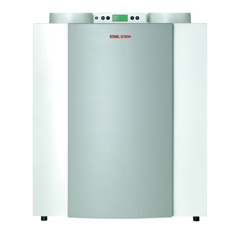
STIEBEL ELTRON LWA 203 User manual

Technik zum Wohlfühlen
LWA 203, LWA 203 SOL, LWA 303, LWA 303 SOL
Central ventilation device with heat recovery
Operating and installation instructions
267093
Index
1. Operating instructions
for users and contractors 2
1.1 Equipment summary
1.2 Equipment description 2
1.3 Operating and installation instructions 2
1.4 Important information 3
1.5 Operation 3
1.6 Settings 4
1.7 FE 7 remote control 13
1.8 Maintenance and cleaning 13
1.9 What to do if ...? 13
2. Installation instructions
for contractors 14
2.1 Equipment layout 14
2.2 Specification 16
2,3 Equipment description 18
2.4 Instructions and regulations 18
2.5 Installation 20
2.6 Commissioning 27
2.7 Maintenance and cleaning 27
2.8 LZM II commissioning summary 28
2.9 Adjustments (control level 3) 30
2.10 Troubleshooting 37
2.11 Commissioning list 39
Connection examples 40 - 42
4. Environment/recycling 43
5. Customer service/warranty 43
26_04_01_0010_a
The installation (water and electrical work) and commissioning, as well as the maintenance of this equipment, must only be carried out by an
authorised qualified contractor in accordance with these instructions.
2
Summary of LZM II functions
RS 232 interface for adjustment and
monitoring via a PC
System extension through the FE 7 remote
control
Input of the system and heat pump frost
protection limits
At least 24 h backup power for the clock
Automatic pump kick-start
Reset option
Stored fault list with precise fault code
indication, together with date and time
display
Rapid and accurate fault diagnostics using
system analysis including temperature
scan for heat pump and peripheral
equipment without requiring additional
equipment
Factory settings for time switch programs
for all heating and DHW circuits
1.2 Equipment description
This device is a complete system with
heat recovery for central extraction and
decentralised ventilation, as well as for DHW
and central heating.
The air/water heat pump recovers waste heat
from the extracted air via a duct system. This
energy is channelled to the heating and/or
DHW system. The cooled air is expelled to
the outside. When the outside temperature is
very low, or when the heating requirement is
very high, the device covers the residual heat
demand of the system via an integral electric
booster heater.
Outside wall valves channel in fresh air; which
replaces air expelled by the heat pump.
The device is controlled by the weather-
compensated flow temperature controller LZM
II.
An additional push button (G) is built into the
plastic facia (Fig. 1). By activating this push
button, the electric booster heater heats the
DHW once to 65 °C in the upper third (or the
upper quarter for SOL versions) of the DHW
cylinder.
Special features of the SOL versions
These versions have an additional indirect coil
built into the DHW cylinder for DHW heating
with solar energy.
1.3 Operating and installation
instructions
Subject to the relevant system, also observe
the operating and installation instructions
of the components of which the system
comprises.
Keep these operating and installa-
tion instructions safely and pass them
on to any new user, should the equipment
change hands, and let your contractor check
their content in conjunction with any mainte-
nance and repair work.
1. Operating instructions for users and contractors
B
C
ED
F
A
6
7
8
9
10
1
2
3
4
5
11
1.1 Equipment summary
C26_03_01_0118
GH
A Display
B Rotary selector
C Rotary selector Reset / Auto
D Programming key
E Programming indicator
F Optical interface RS 232
G Immersion heater push button
H Safety pressure limiter control indicator
(see 1.9 "What to do if...?")
System status display
1 Mixer open
2 Mixer close
3 Circulation pump, heating circuit 2
"mixer circuit"
4 Circulation pump, heating circuit 1
5 Electric booster stages "heating"
6 Compressor
7 Ventilation
8 Defrosting
9 DHW heating
10 Solar circuit pump
11 Equipment menu
3
1.5 Operation
The operation is split over three control levels.
Control levels 1 and 2 are accessible to users
and contractors alike. Control level 3 is only
designed for qualified contractors.
Control level 1 (control flap closed)
Here, you can adjust the operating modes,
such as standby mode, automatic mode,
constant day or setback mode, etc.
Control level 2 (control flap open)
Here, you can adjust the system parameters,
such as room temperatures, DHW
temperatures, heating programs, etc.
Control level 3 (for contractors only)
This level is protected by a code and should
only be used by contractors. Here, you can
determine the specific details regarding the
ventilation equipment and heating system.
Do not change any system-specific settings
at the control unit. Your contractor has
set the control unit specifically to suit the
conditions of your home and to your personal
requirements.
Vital facts in brief
Settings
All settings follow the same pattern:
Opening the
control flap toggles the
LZM II into programming mode. A symbol
is shown at the bottom of the display at
system parameter ROOM TEMP 1.
Turning the rotary selector allows you
to move the indicator to the parameter you
want to change.
Press to change the value of the
parameter. Whenever the red indicator
above illuminates, you can modify the
current value by turning the rotary selector
. Press again; the illuminator then
extinguishes and the new set value has been
saved. You can modify further values for this
parameter by pressing if the red indicator
has not been extinguished above . The
programming step can only be terminated
when the red indicator has extinguished.
Terminating the programming process
You can terminate the process after entering
and saving the required parameter changes
by closing the control flap. However, if you
want to make further changes, turn the
rotary selector until the display shows
BACK, then press This will return you
to the previous level. Closing the control
flap with illuminated indicator above
returns the LZM II into its original state. The
modified value will then not be saved.
During commissioning, a system
check will be implemented, e.g.
all sensors that are currently connected
are displayed upon request. Sensors not
connected before the system goes ‘live’
are not registered by the LZM II and are
therefore not displayed. The indicator
symbol skips that parameter.
1.4 Important information
During commissioning or after the heat-up
program has terminated, the LZM II display
shows "Waiting for IBN". The DHW and the
ventilation programs are switched OFF and
the compressor will be blocked. The electric
booster stages are only used to ensure frost
protection.
Only the emergency operating mode can be
selected.
You can only select the required operating
mode after setting the controller to
emergency mode.
!
Never
use extracted air loaded with grease,
explosive gases, dust or adhesive
aerosols
connect cooker hoods to the ventilation
system
heat liquids other than DHW or heating
water
install the equipment
a) outside
b) in rooms where there is a risk of
frost
c) in wet areas, e.g. bathrooms
operate the equipment
a) without expelled air and extract
air ducts
b) without decentralised
ventilation elements
c) without ventilation function
d) with an empty cylinder
e) without minimum circulation
volume
f) during building work
(ventilation and heat pump)
Risk of injury
Where children or persons with
limited physical, sensory or mental capa-
bilities are to be allowed to control this
appliance, ensure that this will only happen
under supervision or after appropriate in-
structions by a person responsible for their
safety.
Children should be supervised to ensure
that they do not play with the appliance.
4
Fan running
Display (including all elements)
1.6 Settings
1.6.1 Operating modes
(control level 1)
The operating modes are changed by turning
the rotary selector with the control flap
closed.
Standby mode
Standby mode affects heating, DHW
and ventilation functions. When the
outside temperature is above +4 °C,
DHW and central heating functions are
switched off. Below +4 °C, the DHW
cylinder is held at 40 °C and the heating
circuit temperature is held at a setback
temperature of +15 °C.
Before DHW heating, the heat pump runs
in heating mode for approx. 2 minutes.
Ventilation runs in setback mode.
The power OFF function is active, when
the indicator flashes.
Application: During holidays.
Automatic mode
Heating according to time switch
program: Changeover between day
temperature and setback temperature;
remote control is active.
Application: When DHW and central
heating are required.
Constant day mode
The heating circuit is constantly held at
the day temperature (applicable to HC 1
and HC 2).
DHW and ventilation functions are active.
Application: Low energy houses without
setback mode.
Constant setback mode
The heating circuit is constantly held at
the setback temperature (applicable to
HC 1 and HC 2). DHW and ventilation
functions are active.
Application: During weekends away.
DHW mode
DHW and ventilation functions are active.
Frost protection is enabled for central
heating operation.
Application: The heating season has
ended; only DHW should be generated
(summer mode).
(Emergency mode) Booster heater
This setting activates the emergency
operation. In this operating mode,
the booster heater provides central
heating, irrespective of the dual-mode
changeover point.
The DHW and the ventilation programs
are switched OFF and the compressor
will be blocked.
Fault message (flashing)
Indicates faults in the ventilation system.
Notify your local contractor.
24
12
18 6
V
C
C
Emergency mode (booster heater)
DHW mode
Constant setback mode
Constant day mode
Automatic mode
Standby mode
Fault message (flashing)
14-digit plain text display
Compressor running
Heating times for DHW and central heating (black)
Booster heater in operation
Switching time pairs for central heating and DHW operation
Day mode for heating circuit 1
Setback mode for heating circuit 1
26_03_01_0119
Defrosting
5
With system parameters ROOM TEMP 1 and ROOM TEMP 2 you can select the room temperature
for day and setback mode for heating circuits 1 and 2. The lowest temperature that can be set
is 15 °C. You can change the room temperature, if you feel rooms are either too hot or too cold.
The display ROOM TEMP 2 will only be displayed, if the mixer flow sensor is connected. The given
value is useful for calculating the heating circuit flow temperature.
The actual room temperature can also be scanned, as soon as the FE 7 remote control has been
connected and allocated to heating circuit 1.
With parameter VENTILATION, you can adjust the operating modes for ventilation operation.
With parameter DHW TEMP you can allocate a set day and night temperature to the temperature
inside the DHW cylinder.
With parameter TIME/DATE, you can adjust the time and the summer time.
At the factory, summer time is set to begin on the 25 March and to end on the 25 October.
When parameter HOLIDAY PROG is selected, the heat pump system operates in setback mode.
Frost protection is activated for the DHW cylinder.
In parameter PARTY PROG, you can extend the day mode by a few hours.
In parameter INFO TEMP, you can scan the sensor temperatures of the ventilation and heat pump
system, comparing set with actual temperatures.
In parameter HTG CURVE, you can adjust one heating curve respectively for heating circuit 1 and
2. The room temperature will only remain constant, irrespective of the outside temperature, if the
correct heating curve has been selected for the relevant type of building. Selecting the correct
heating curve is therefore vitally important.
In parameter HTG PROG, you can adjust the heating programs for heating circuit 1 and 2.
In parameter DHW and VENTILATION PROG, you can adjust the times for the day and setback
temperatures for DHW heating.
During COMMISSIONING, you need to determine the settings of control level 2 and the system-
specific parameters. These parameters are adjusted at control level 3 by your heating contractor,
access to which is protected by code.
Your contractor needs to check all parameters in sequence, and enter all selected values into the
column (system value) provided in the commissioning report.
1.6.2 Overview of system parameters (control level 2)
Select the required parameter with the rotary selector.
For adjustments to parameters, turn to page 6.
ROOM T HC1
ROOM T HC2
DHW TEMP
TIME / DATE
HOL / PARTY
TEMPERATURES
HTG CURVES
HTG PROG
DHW PROG
START UP
6
Room temperature
With parameter ROOM TEMP 1 or 2, you can
adjust the Set room temperature for the day
and setback mode of heating circuit 1 or 2.
Changing these parameters results in a parallel
offset of the heating curve.
The actual room temperature can also be
scanned, as soon as the FE 7 remote control
has been connected and allocated to heating
circuit 1 or 2.
PRG
PRG
PRG
PRG
PRG
PRG
DHW temperature
With parameter DHW TEMP, you can allocate
a set day and night temperature to the
temperature inside the DHW cylinder.
Open the control flap.
Ventilation
With parameter VENTILATION, you can adjust
the operating modes for ventilation operation.
When the required operating mode is shown,
press PRG; the operating mode is then set.
In addition, the display will be reset by turn-
ing the rotary selector to Filter reset and
subsequent pressing of PRG as well as setting
to ON followed by repeatedly pressing PRG.
Open the control flap.
Settings at control level 2 for users and contractors
PRG
PRG
PRG
PRG
PRG
PRG
Standby
or
Filter reset
ROOM T HC1
SET ROOM T DAY
SET ROOM T DAY
SET ROOM T NGT
SET ROOM T NGT
ACTUAL ROOM T
BACK
ROOM T HC1
DHW TEMP
SET DHW T DAY
SET DHW T DAY
SET DHW T NGT
SET DHW T NGT
ACTUAL DHW T
DHW TEMP
BACK
7
Time and date
With parameter TIME/DATE, you can adjust the
time and the Summer time.
At the factory, summer time is set to begin on
the 25 March and to end on the 25 October.
PRG
PRG
PRG
PRG
PRG
PRG
PRG
PRG
Open the control flap.
Setting the time
or
Summer time
Holiday and party program
The holiday program controls heating, DHW
and ventilation functions. When the outside
temperature is above +4 °C, heating and DHW
functions are switched off. Below
+4 °C, the DHW cylinder is held at 40 °C and
the heating circuit temperature is held at a
setback temperature of +15 °C.
Before DHW heating, the heat pump runs in
heating mode for approx. 2 minutes.
Ventilation runs in setback mode.
Holiday mode is shown on the display with
the flap closed. For the start of the holidays,
the year, month and day are entered; also
enter the year, month and day for the end
of the holidays. The start and end time is
always 24:00 h of the date entered. After the
holiday period has expired, the heat pump
system operates again in accordance with the
previous heating and DHW program.
In Party mode, you can extend the day mode
for central heating by a few hours. This is
displayed with the flap closed.
For example, if the heating program normally
switches to setback mode at 22:00 h, and you
set the party mode to two hours, then setback
mode would only begin at
24:00 h.
PRG
PRG
PRG
PRG
PRG
PRG
PRG
PRG
PRG
Open the control flap.
PRG
PRG
PRG
PRG
PRG
PRG
PRG
PRG
PRG
TIME / DATE
SET CLOCK
TIME
TIME
YEAR
MONTH
DAY
SET CLOCK
BACK
TIME / DATE
HOL/PARTY
HOLIDAY
YEAR START
MONTH START
DAY START
YEAR STOP
MONTH STOP
DAY STOP
HOLIDAY
BACK
HOL / PARTY
8
Open the control flap.
Info temperatures
The parameter INFO TEMP enables you to
scan the ventilation equipment or ventilation
system Sensor temperatures, comparing set
with actual values, the Heating curve gap,
etc. In all, the following parameters can be
scanned:
– Outside temperature
– Actual room temperature (HC 1/HC 2)
(this will only be displayed if the FE 7 is
connected)
– Set room temperature FE 7
(this will only be displayed if the FE 7 is
connected)
– Actual DHW temperature
– Set DHW temperature
– Actual flow temperature (HC 1)
– Set flow temperature (HC 1)
– Actual mixer flow temperature (HC 2)
– Set mixer flow temperature (HC 2)
– Extract air temperature
– Min. extract air temperature
– Evaporator temperature
– Min. evaporator temperature
– Cylinder temperature
– Return temperature HC
– Actual mixer temperature
– Set mixer temperature
– Lower cylinder temperature
– Collector temperature
Note:
Actual or set temperatures will not be
displayed, if the corresponding sensor is not
connected.
Open the control flap.
Heating curves
In parameter HTG CURVES, you can adjust one
Heating curve respectively for heating circuit
1 and 2. Selecting the correct heating curve is
therefore vitally important.
Note: Your contractor will have set up a
building and system-specific optimum heating
curve for every heating circuit. It relates to the
HP return temperature for heating circuit 1
and to the mixer flow temperature for heating
circuit 2.
When adjusting the heating curve at the
LZM II, the calculated return or flow
temperature, which is subject to the outside
temperature and the set room temperature,
will be shown at the top of the display.
Bezogen auf +20 °C
Außentemperatur
Bezogen auf 0 °C
Außentemperatur
Bezogen auf -20 °C
Außentemperatur
Tag-Betrieb Heizkreis 1
Bezogen auf +20 °C
Außentemperatur
Bezogen auf 0 °C
Außentemperatur
Bezogen auf -20 °C
Außentemperatur
Absenk-Betrieb
26_03_01_0076
Relative to +20°C
outside temp.
Relative to 0°C
outside temp.
Relative to -20°C
outside temp.
Day mode Heating circuit 1
Setback mode
Relative to +20°C
outside temp.
Relative to 0°C
outside temp.
Relative to -20°C
outside temp.
As soon as a temperature has been pre-
selected via the fixed temperature parameter
at control level 3, heating circuit 1 will be
hidden, and the display will show Fixed temp.
with the relevant temperature.
TEMPERATURES
OUTSIDE
BACK
TEMPERATURES
HTG CURVE
BACK
HTG CURVE
9
Heating curve diagram
One heating curve respectively can be adjusted for heating circuit 1 and heating circuit 2.
At the factory, heating curve 0.6 is set up for heating circuit 1 and heating curve 0.2 for
heating circuit 2.
These heating curves relate to a set room temperature of 20 °C.
Adjustment of programmed changeover between day and setback mode
The figure shows a standard heating curve with a slope of 0.8, relative to a set room
temperature for day mode of 20 °C. The lower curve represents the setback curve. For this, the
set room temperature for setback mode of 15 °C is used, in other words the heating curve is
subjected to a parallel offset.
Matching a heating curve to actual conditions
Example: During spring and autumn, the return or flow temperature of a heating system is too
low at an outside temperature between 5 and 15 °C, but is OK at outside temperatures of
≤ 0 °C. This problem can be remedied with a parallel offset and a simultaneous reduction of
the heating curve.
Prior to this adjustment, Heating curve 1.0 was adjusted, relative to a Set room temperature
of 20 °C. The dotted line indicates the modified Heating curve at 0.83 and a modified Set room
temperature at 23.2 °C.
26_03_01_0077
1,5
2
1,2
1
0,6
0,4
0,2
2,53
20
18
16
14
12
10
8
6
4
2
0
-2
-4
-6
-8
-10
-12
-14
-16
-18
-20
100
80
60
40
20
Außentemperatur [°C]
Heizkreis 2 WP-Vorlauftemperatur [°C]
Heizkreis 1 WP-Rücklauftemperatur [°C]
0,8
20
18
16
14
12
10
8
6
4
2
0
-2
-4
-6
-8
-10
-12
-14
-16
-18
-20
Außentemperatur [°C]
70
60
50
40
30
20
Tag-Betrieb
Absenk-Betrieb
Rücklauf- / Vorlauftemperatur [°C]
20
18
16
14
12
10
8
6
4
2
0
-2
-4
-6
-8
-10
-12
-14
-16
-18
-20
Außentemperatur [°C]
Rücklauf- / Vorlauftemperatur [°C]
70
60
50
40
30
20
geänderte Heizkurve
26_03_01_0078
26_03_01_0079
Outside temperature °C
Heating circuit 1 HP return temperature [
°C]
Heating circuit 2 HP flow temperature [
°C]
Day mode
Setback mode
Return/flow temperature [
°C]
Return/flow temperature [
°C]
Modified heating curve
2.5
1.5
1.2
0.8
0.6
0.4
0.2
1
2
10
Heating programs
In parameter HTG PROGS, you can adjust the
heating programs for Heating circuit 1 and 2.
You can adjust your heating system as follows:
– for every day of the week
(Monday, ..., Sunday)
– Monday to Friday (Mo - Fr)
– Saturday and Sunday (Sa - Su)
– the whole week (Mo - Su)
You can adjust three switching time pairs
(I, II, III) for each of these options.
This determines when and how often the
ventilation system should heat in day mode.
At all other times, the ventilation equipment
operates in setback mode. You will already
have selected the corresponding set values for
day and setback mode under parameter ROOM
TEMP 1/2.
Example:
For heating circuit 1, your heating system
should operate daily from Monday to Friday
at two different times, i.e. from 05:30 h until
08:30 h as well as from 14:00 h until 22:00 h.
For the weekend, your heating system should
provide heat from 08:30 h until 21:00 h.
Open the control flap.
Heat circuit 1
or
Heating circuit 2
HTG PROG
HEAT CIRCUIT 1
MON - FRI
HEATING START
HEATING STOP
SAT - SUN
BACK
BACK
HTG PROG
HEATING START
HEATING STOP
HEATING START
HEATING STOP
HEATING START
HEATING START
HEATING START
SAT - SUN
11
DHW and ventilation program
In parameter DHW VENTILATION PROG,
you can adjust the times for the day and
setback temperatures for DHW heating or the
Ventilation program.
You can adjust the DHW heating or ventilation
as follows:
– for every day of the week
(Monday, ..., Sunday)
– Monday to Friday (Mo - Fr)
– Saturday and Sunday (Sa - Su)
– the whole week (Mo - Su)
You can adjust three switching time pairs
(I, II, III) for each of these options.
Exception: You will need two switching time
pairs, if you want to define a program from
22:00 h until 06:00 h the following day.
Thereby you determine how often, during
day and setback mode, the ventilation device
should provide DHW and when the ventilation
should run in either day or setback mode. You
will already have selected the corresponding
set values for day and setback mode under the
system parameter DHW TEMP.
Example:
You want to heat up DHW daily at two
different times, i.e. from 22:00 h until 06:00 h
the following day, and then again from
08:00 h until 09:00 h.
The day begins at 00:00 h; therefore begin
programming for this example at 00:00 h. The
first switching times pair runs from
00:00 h until 06:00 h. The second switching
times pair runs from 08:00 h until 09:00 h. The
third switching times pair runs from 22:00 h
until 24:00 h.
Open the control flap.
PRG
24
12
18 6
24
12
18 6
24
12
18 6
24
12
18 6
24
12
18 6
24
12
18 6
PRG
PRG
PRG
PRG
PRG
PRG
PRG
PRG
PRG
PRG
24
12
18 6
24
12
18 6
24
12
18 6
24
12
18 6
24
12
18 6
24
12
18 6
PRG
PRG
PRG
PRG
PRG
PRG
PRG
PRG
PRG
DHW PROG
MON - SUN
DHW START
DHW START
DHW STOP
DHW START
DHW STOP
MON - SUN
BACK
DHW PROG
DHW STOP
DHW PROG
12
Standard settings
At the factory, the heat pump manager is programmed with the following standard settings:
Switching times1) for heating circuit 1 and heating circuit 2 H1 / H2 (day mode)
Monday - Friday
Saturday - Sunday
6:00 - 22:00
7:00 - 23:00
Room temperature 1 / 2
Room temperature in day mode
Room temperature in setback mode
20 °C
20 °C
Switching times2) for DHW program (day mode) and ventilation program
Monday - Friday
Saturday - Sunday
5:00 - 21:00
6:00 - 23:00
DHW temperature
DHW DAY T
DHW setback temp.
50 °C
50 °C
Heating curve slope
Heating curve 1
Heating curve 2
0.6
0.2
Heating circuit 1 Heating circuit 2
Switching times
pair I
Switching times
pair II
Switching times
pair III
Switching times
pair I
Switching times
pair II
Switching times
pair III
Mo
Tu
We
Th
Fr
Sa
Su
Mo - Fr
Sa - Su
Mo - So
Heating and ventilation programs
You may enter your only individual programs into the following tables.
DHW program Ventilation program
Switching times
pair I
Switching times
pair II
Switching times
pair III
Switching times
pair I
Switching times
pair II
Switching times
pair III
Mo
Tu
We
Th
Fr
Sa
Su
Mo - Fr
Sa - Su
Mo - Su
1) Only for switching times pair 1; switching times pairs 2 and 3 are not pre-programmed.
2) Only for switching times pair 1; switching times pairs 2 is not pre-programmed.
13
1.7 FE 7 remote control
26_03_01_0107
With the FE 7 remote control, the following
options are available:
– changing the set room temperature for
heating for heating circuit 1 or 2 by ± 5 °C.
– changing the operating mode.
It offers the following controls:
one rotary selector for changing the set
room temperature
one rotary selector with the following
positions
Automatic mode
Constant setback mode
Constant day mode

The remote control is only active when
the LZM ll is in automatic mode.
1.9 What to do if . . . ?
. . . the fan symbol flashes on the
display:
Clean the extract filter, as described in section
1.8
. . no hot water is available:
Should you fail to obtain hot water at any
time, you can take the following steps to
remedy that situation.
No electrical power:
Check the fuse/circuit breaker in your fuse box.
If it has blown/tripped, replace/reset the fuse/
MCB. Notify your local contractor if the fuse/
MCB blows/trips again.
Despite electrical power:
Check, whether the air inlet/outlet is blocked.
. . . the safety valve of the cold water supply
line drips:
This may occur during the heat-up phase and
is completely normal as water expands when
heated.
. . . the pumps start briefly outside the heating
period:
An automatic pump start (10 s) is
programmed, to prevent the pumps from
seizing up outside the heating periods.
... the red indicator in the fascia illuminates:
In this situation the safety pressure limiter
has responded and may only be reset by your
contractor.
After a heat pump has been switched OFF, a
fixed residual idle time of 20 minutes is set
to protect the compressor. The heat pump
restarts automatically at the end of the idle
time.
Always notify your local contractor in
case of any other faults.
1.8 Maintenance and cleaning
Maintenance work, e.g. checking the
electrical safety, must only be carried
out by qualified personnel.
Protect the equipment from dust and dirt
ingress during building work.
A damp cloth is sufficient for cleaning all
plastic parts. Never use scouring or solvent-
based cleaning agents.
Keep the air inlet and outlet
apertures in the outside walls free
from snow and leaves.
A contractor should check and possibly clean
the evaporator and fan at least once a year.
Condensate drain
Check the condensate drain at least once every
month. Remove dirt and blockages.
External wall valves
Regularly check, clean and, if required, replace
the filters in the external wall valves.
Replace the filter elements at least annually.
Cleaning the extract air filters
Switch the ventilation system OFF before
26_03_01_0109
opening the filter cassette.
The LZM II contains a filter cleaning indicator
that automatically reminds users every 3
months to clean the filters. This is indicated by
a flashing fan symbol on the display.
The display can be reset at the control level
2 under parameter VENTILATION under
Filter reset by pressing PRG and setting the
system to ON and repeatedly pressing PRG.
The controller switches automatically over to
standby mode if no reset has been carried out
after 7 days.
A
The filter retainer can only be withdrawn to-
wards the front. This enables you to pull out
the filter and check it for contamination.
Replace the filter if it is heavily soiled (solid
layer of dust on the top of the filter mat). Clean
the filter with a vacuum cleaner, if it is only
lightly soiled. The filter cannot be washed.
Washing would mat the fabric, leaving too lit-
tle air to flow through the filter. After inserting
the filter, refit the cover.
When inserting the filter ensure that the solid,
fine-pored side is turned towards the r.h. side,
i.e. towards the evaporator.
Never adjust the ventilation and extract air
valves inside the rooms. These have been
adjusted during commissioning.
All other work on the equipment
must only be carried out by qualified
contractors. Never adjust the ventilation and
extract air valves inside the rooms. These
have been adjusted during commissioning.
Never make any modifications to the inter-
nal equipment electrics or controls.
14
1 32 4 5
9
11
10
12
14
25 26 27
23 24
28
20
16
18
3029 31
6
13
7
8
22
21
View X
X
17
15
C26_04_01_0014_a
Fig. 3
Standard versions
1 Extract connection DN 160
2 Evaporator
3 Heating circuit pump
4 Quick-acting air vent valve
5 Solenoid valve (DHW)
6 Electric booster (heating)
7 Solenoid valve (heating)
8 Expelled air connection DN 160 (optional)
9 High pressure limiter
10 Fluid separator
11 Temperature sensor (defrosting)
12 Condenser - heating
13 Compressor
14 Condenser - DHW
15 Temperature sensor HP (60 °C)
16 Temperature sensor (65 °C - controller)
Single DHW heating via booster heater
17 Protective anode (2x)
18 Electric booster (DHW)
20 Temperature sensor STB
21 DHW cylinder
22 Common dryer
23 Expansion valve
24 Expansion valve sensor
25 Temperature sensor (return)
26 Fill & drain valve (heating)
27 Heating return
28 Heating flow
29 Heating return (mixer circuit)
30 Temperature sensor (flow)
31 Fan
32 Extract filter cassette
2.1 Equipment layout
for contractors
2. Installation instructions
32
15
1 32 4 5
10
12
15
25
26 27 28
20
19
18
14
3029 31
6
13
7
8
21
View X
X
17
16
9
11
23
22
24
C26_04_01_0015_a
1 Extract connection DN 160
2 Evaporator
3 Heating circuit pump
4 Quick-acting air vent valve
5 Solenoid valve (DHW)
6 Electric booster (heating)
7 Solenoid valve (heating)
8 Expelled air connection DN 160 (optional)
9 High pressure limiter
10 Fluid separator
11 Temperature sensor (defrosting)
12 Condenser - heating
13 Compressor
14 Heat exchanger for solar
DHW heating
15 Condenser - DHW
16 Temperature sensor HP (60 °C)
(DHW top)
17 Protective anode (2x)
18 Electric booster (DHW)
19 Temperature sensor (65 °C - controller)
Single DHW heating via booster heater
20 Temperature sensor STB
21 DHW cylinder
22 Common dryer
23 Expansion valve
24 Expansion valve sensor
25 Temperature sensor SOL
(DHW bottom)
26 Fill & drain valve (heating)
27 Heating return
28 Heating flow
29 Heating return (mixer circuit)
30 Temperature sensor (flow)
31 Fan
32 Extract filter cassette
Fig. 4
SOL version
32
16
2.2 Specification (The details listed on the type plate apply)
1) (L20/F40/W35) = extract temperature 20 °C, extract air rel. humidity 40 %, heating flow temperature 35 °C
2) (L20/F40) = extract air temperature 20 °C, extract air rel. humidity 40 %
Type LWA 203 LWA 203 SOL LWA 303 LWA 303 SOL
Part no. 07 42 60 07 42 62 07 42 61 07 42 63
Dimensions H / W / D mm 1990 x 775 x 775
Weight dry/wet kg 187 / 490 212 / 498 190 / 493 215 / 501
Output details
Application range - extract air °C 15 - 30 15 - 30 15 - 30 15 - 30
Heating output HP at 250 m³/h/200 Pa and
(L20/F40/W35)1)
kW 1.5 1.5 2.1 2.1
Coefficient of performance HP to EN 255 part 2 (COP) 4 4 4 4
Coefficient of performance HP to EN 255 part 3 (COP(t)) 4.1 4.1 3.7 3.7
Heating output electric booster (heating) kW 6.6 6.6 6.6 6.6
Heating output electric booster (DHW) kW 1.5 1.5 1.5 1.5
Heating output HP (L20/F40/W35)1)+ electric booster kW 8.1 8.1 8.7 8.7
DHW heat-up time with HP from 15°C to 55 °C (L20/F40)2) h 10.1 9.0 7.3 6.5
Electrical specification
Max. power consumption kW 8.6 8.6 8.8 8.8
Max. power consumption A 17.5 17.5 18 18
Starting current (HP) A 10 10 13 13
Power consumption - fan at 250 m3/h / 200 Pa W 50 50 50 50
Power consumption - circulation pump W 46-93 46-93 46-93 46-93
Power supply electric booster + compressor (L1, L2, L3) n x mm25 x 2.5 5 x 2.5 5 x 2.5 5 x 2.5
Mains transformer + control unit (L,N) n x mm23 x 1.5 3 x 1.5 3 x 1.5 3 x 1.5
Fuse electric booster + compressor (L1, L2, L3) A 20 gl 20 gl 20 gl 20 gl
Fuse transformer, control unit, pump and fan (L, N) A 16 gl 16 gl 16 gl 16 gl
Voltage / Frequency - power unit V / Hz 3/N/PE ~ 400 / 50
Voltage / Frequency - control unit V / Hz 1/N/PE ~ 230 / 50
Protection EN 60529 (DIN VDE 0470) IP 20 IP 20 IP 20 IP 20
Heat pump
Permissible operating pressure, refrigeration circuit Mpa 2.34 2.34 2.34 2.34
Refrigerant Type R 134 a R 134 a R 134 a R 134 a
Fill level g 1000 1000 1000 1000
Central heating
Permissible operating pressure heating circuit MPa 0.3 0.3 0.3 0.3
Minimum heating volume flow l/h 400 400 400 400
Available pressure differential at the circulation pump at 400 l/h:
Speed stage 1
Speed stage 2
Speed stage 3
MPa
MPa
MPa
0.02
0.04
0.05
0.02
0.04
0.05
0.02
0.04
0.05
0.02
0.04
0.05
Temperature spread only for HP operation
400 l/h (L20/F40/W35)1) K 3 3 4 4
Hot water
Permissible operating pressure DHW Mpa 0.6 0.6 0.6 0.6
Maximum DHW temperature via heat pump °C 60 60 60 60
Capacity DHW cylinder l 303 290 303 290
Ventilation
Extract volume flow for ventilation only m3/h 70 – 290 70 – 290 70 – 290 70 – 290
Minimum extract volume flow for HP operation m3/h 125 125 175 175
Max. available external pressure 250 m3/h air flow rate Pa 270 270 270 270
Max. permissible external pressure at nominal and minimum flow
rate
Pa 150 150 150 150
Connections
Heating connection mm Ø 22 (male) Ø 22 (male) Ø 22 (male) Ø 22 (male)
DHW connection Ø 22 (male) Ø 22 (male) Ø 22 (male) Ø 22 (male)
DHW circulation connection R ½" (male) R ½" (male) R ½" (male) R ½" (male)
Condensate connection mm Ø 22 female (hose 2 m long)
Water connection heat exchanger inch G 1 (male) G 1 (male)
Expelled air/extract air connections DN 160 160 160 160
Sound power level dB(A) 48 48 48 48
17
Accessories
Type Part no. Description
AFS 2 16 53 39 Outside temperature sensor
PT1000 immersion sensor 16 58 18 Solar collector sensor (only for SOL versions)
Special accessories
Contact sensor AVF 6 16 53 41 Flow sensor for heating circuit 2
PTC immersion sensor TF 6A 16 53 42 Residual heat sensor for central heating backup
External wall air outlet 07 31 84 Decentralised fresh air supply
FE 7 18 55 79 Remote control with room sensor
Filter mat set 22 13 99
C26_04_01_0029
0,1
00 0,2 0,4 0,6 0,8 1,0 1,2 1,4 1,6
[m³/h]
[bar]
0,2
0,3
0,4
0,5
0,6
I
II
III
0
50
100
150
200
250
300
350
400
450
Volumenstrom [m³/h]
0 50 100 150 200 250 300
Externe Pressung [Pa]
2 V 3 V 4 V 5 V 6 V 7 V 8 V 9 V 10 V
26_04_01_0031
Heating pump curve *
* available at the equipment connector
Fan curve
Flow rate [m3/h]
External pressure [Pa]
Specification - control unit (LZM II)
Supply voltage 230 V ~ ± 10 %, 50 Hz
Power consumption Max. 8 VA
EN 60529 Protection IP 1XB
EN 60730 Class II
Function type 1B
Software - class A
Control panel integration to DIN 43700 Cut-out 138 x 92
Clock backup, day > 10 hours
Permiss. ambient temperature during opera-
tion 0 to 50 °C
Permiss. ambient temperature during storage - 30 to 60 °C
Sensor resistances Test resistance at 2000 Ω
Communication system RS232 (optical), CAN
Max. relay output capacities
Mixer circuit pump 2 (1.5) A
Mixer 2 (1.5) A
Solar circuit pump 2 (1,5) A
Max. total relay output capacity 6,3 (6,3) A
18
26_04_01_0113
2.3.2 Function
Air is supplied by the extractor fan (1) and
channelled outside via the evaporator (14).
The energy made available by the heat pump
during this process is transferred to the
DHW or central heating system via separate
condensers (4and 10).
When the heating system demands lots of
energy at low outside temperatures, the
additional energy required is supplied by the
electrical booster (3).
When there is a high DHW demand, the DHW
is heated by an electric immersion heater (8).
2.3 Equipment description
2.3.1 Function diagram
1 Extract fan
2 Compressor
3 Electric booster (heating)
4 Condenser - heating
5 Circulation pump
6 Diverter valves
7 Non-return valve
8 Electric immersion heater (DHW)
9 Heat exchanger/indirect coil
10 Condenser - DHW
11 DHW cylinder
12 Non-return valve
13 Common dryer
14 Evaporator
15 Expansion valve
16 Non-return valve
I Extract air
II Expelled air
III Expelled air (optional)
IV Hot water
V DHW circulation
VI Cold water
2.4 Instructions and regulations
On the water side:
DIN 4751 sh. 1 and 2: Safety equipment for hot
water heating systems
DIN 1988: Technical rules for DHW installations
TRD 721: Safety equipment to prevent excess
pressure - safety valves, or local regulations.
On the electrical side:
DIN VDE 0100: Regulations for the installation
of HV systems with rated voltages up to
1000 V.
VDE 0701: Regulations regarding the repair,
modification and testing of used electrical
equipment.
TAB: Technical connection conditions for
connections to the LV mains.
On the refrigerant side:
EN 378: Safety and environmental
requirements, or local regulations.
On the air side:
DIN 1946 T1, T2, T6 - Ventilation and air
conditioning
DIN 2088 - Domestic ventilation equipment
VDI 2087 - Air ducts
General:
Collation of technical requirements for boiler
rooms, e.g. Boiler Room Directives or national/
local Building Regulations, commercial and
fire as well as emission control regulations
and requirements, or local regulations.
TA-Lärm: Technical instructions to protect
against noise emissions.
Fig. 5
19
26_04_01_0016_a
26_04_01_0017_a
26_04_01_0111
Fig. 6
Fig. 8
Fig. 7
775
1966
660
680
740
> 100
775
min. 500
2300
Dimensions in mm
20
503,5
80
1498
334
156
1264
1055
558
194
56
22 - 40 verstellbar
1755
376
C26_04_01_0112
2.5 Installation
2.5.1 Transport and positioning
To protect the equipment against damage,
it must be transported vertically inside
its dedicated packaging. Where space is
restricted, you may also move the equipment
tipped backwards at an angle.
2.5.2 Positioning
1. Undo the four screws from the non-
returnable pallet.
2. Remove the washers.
3. Before removing the equipment from
the pallet, remove the anti-vibration
mounts from the pack supplied with
the equipment, and insert fully into the
equipment.
4. Remove the equipment from its pallet and
position it where required.
5. Level the equipment by manipulating the
anti-vibration mounts.
The equipment is designed for the installation
of the expelled air pipe at the top, for example
leading off to the right (see Fig. 9).
Connection dimensions
1 Cold water supply
2 DHW connection
3 Condensate drain
4 Circulation connection
5 Heating flow
6 Heating return, heating circuit 1
7 Heating return, heating circuit 2
8 Fill & drain valve, heating water
9 HE flow*
10 HE return*
11 Extract air connections
12 Expelled air connections
(optional installation)
13 Fill and drainage tap, DHW
14 Safety valve
15 Straight-through shut-off valve
16 Test valve for pressure gauge
17 Non-return valve
18 Test valve
19 Pressure reducing valve
(only in case of 4.8 bar pressure)
20 Electrical cable grommet
21 Circulation pump
22 Sensor well for thermostat *
23 Filter cassette
* Only for SOL versions
Fig. 9
Checking installation conditions
The room in which the equipment is to be
installed must meet the following conditions:
No risk from frost.
Strong floor (wet weight approx. 500 kg).
Never operate the device in rooms at
risk from explosion due to dust, gases or
vapours.
The extract air supplied to the equipment
must not be lower than +15 °C, otherwise
the evaporator would ice-up. Also, the
lower the extracted air temperature, the
lower the heat pump efficiency.
The available floor area in the installation
room must be at least 2 m². Never install
this equipment in rooms with a volume of
less than 4 m³.
Never restrict the available space around
the device through walls or ceilings closer
than shown in Fig. 8.
When installing the ventilation equipment
inside a boiler room, ensure that the
boiler operation will not be impaired.
15 19 18 17 16 15 13 10 1 22
Dimensions in mm
Ø 160
12
11
3
9
20
2
4
14
1721
23
7 5 6 8
2.5.3 Heating water connection
The heat pump must be installed by a
qualified contractor in accordance with the
water installation drawings, which are part of
the engineering documents.
Observe DIN 4751 sheet 1 and 2 plus TRD
721 (safety equipment) regarding the safety
equipment required for the heating system.
Install and adjust an overflow to safeguard an
adequate volume flow through the heat pump
under all operating conditions.
Flow and return connection
Due to the low vibration design of the heat
pump, structure-borne noise is largely
prevented. To facilitate an easy connection to
the heating system, the equipment is supplied
with angled plug-in fittings.
Flushing the heating system
Thoroughly flush the pipework before

This manual suits for next models

3

Other STIEBEL ELTRON Fan manuals

STIEBEL ELTRON LWA 252 Instruction Manual

STIEBEL ELTRON

STIEBEL ELTRON LWA 252 Instruction Manual

STIEBEL ELTRON VCR 180 MC Instruction Manual

STIEBEL ELTRON

STIEBEL ELTRON VCR 180 MC Instruction Manual

STIEBEL ELTRON LWZ 304 SOL User manual

STIEBEL ELTRON

STIEBEL ELTRON LWZ 304 SOL User manual

STIEBEL ELTRON LWZ 70 User manual

STIEBEL ELTRON

STIEBEL ELTRON LWZ 70 User manual

STIEBEL ELTRON LWA 252 Instruction Manual

STIEBEL ELTRON

STIEBEL ELTRON LWA 252 Instruction Manual

STIEBEL ELTRON LWZ 130 J Specification sheet

STIEBEL ELTRON

STIEBEL ELTRON LWZ 130 J Specification sheet

STIEBEL ELTRON VLR 70 L Trend CN Specification sheet

STIEBEL ELTRON

STIEBEL ELTRON VLR 70 L Trend CN Specification sheet

STIEBEL ELTRON VRC-W 400 Instruction Manual

STIEBEL ELTRON

STIEBEL ELTRON VRC-W 400 Instruction Manual

STIEBEL ELTRON LWE 40 Series Instruction Manual

STIEBEL ELTRON

STIEBEL ELTRON LWE 40 Series Instruction Manual

STIEBEL ELTRON LWZ 130 J Specification sheet

STIEBEL ELTRON

STIEBEL ELTRON LWZ 130 J Specification sheet

STIEBEL ELTRON LWZ 304 SOL User manual

STIEBEL ELTRON

STIEBEL ELTRON LWZ 304 SOL User manual

STIEBEL ELTRON VRL-C 300 G Premium User manual

STIEBEL ELTRON

STIEBEL ELTRON VRL-C 300 G Premium User manual

STIEBEL ELTRON KWG 125 User manual

STIEBEL ELTRON

STIEBEL ELTRON KWG 125 User manual

STIEBEL ELTRON LWZ 8 S Trend User manual

STIEBEL ELTRON

STIEBEL ELTRON LWZ 8 S Trend User manual

STIEBEL ELTRON LA 60 VE-A User manual

STIEBEL ELTRON

STIEBEL ELTRON LA 60 VE-A User manual

STIEBEL ELTRON LWZ 130 How to use

STIEBEL ELTRON

STIEBEL ELTRON LWZ 130 How to use

STIEBEL ELTRON LWF FBF 160 Instruction Manual

STIEBEL ELTRON

STIEBEL ELTRON LWF FBF 160 Instruction Manual

STIEBEL ELTRON LWE 40 User manual

STIEBEL ELTRON

STIEBEL ELTRON LWE 40 User manual

STIEBEL ELTRON AWG 315 SR User manual

STIEBEL ELTRON

STIEBEL ELTRON AWG 315 SR User manual

STIEBEL ELTRON LWZ 170 E plus Instruction Manual

STIEBEL ELTRON

STIEBEL ELTRON LWZ 170 E plus Instruction Manual

STIEBEL ELTRON LWZ 304 SOL Instruction Manual

STIEBEL ELTRON

STIEBEL ELTRON LWZ 304 SOL Instruction Manual

STIEBEL ELTRON LWZ 70 E Instruction Manual

STIEBEL ELTRON

STIEBEL ELTRON LWZ 70 E Instruction Manual

STIEBEL ELTRON VCR 180 MC Specification sheet

STIEBEL ELTRON

STIEBEL ELTRON VCR 180 MC Specification sheet

STIEBEL ELTRON AWG 315 SR.2 User manual

STIEBEL ELTRON

STIEBEL ELTRON AWG 315 SR.2 User manual

Popular Fan manuals by other brands

Aereco V2A installation instructions

Aereco

Aereco V2A installation instructions

GUTFELS VENTI 3020R instruction manual

GUTFELS

GUTFELS VENTI 3020R instruction manual

Fanimation Belleria FP4320 Series Specification sheet

Fanimation

Fanimation Belleria FP4320 Series Specification sheet

LUMIT NASIM instruction manual

LUMIT

LUMIT NASIM instruction manual

Vaxcel F0092 quick start guide

Vaxcel

Vaxcel F0092 quick start guide

EGAmaster 79623 operating instructions

EGAmaster

EGAmaster 79623 operating instructions

Valueline VL-SFN16 manual

Valueline

Valueline VL-SFN16 manual

NuTone ARP6 installation instructions

NuTone

NuTone ARP6 installation instructions

Gree FHBQ-D8-K Service manual

Gree

Gree FHBQ-D8-K Service manual

VES Short Case Axial series Installation, operation & maintenance manual

VES

VES Short Case Axial series Installation, operation & maintenance manual

Bionaire BASF1516 instruction manual

Bionaire

Bionaire BASF1516 instruction manual

Airbi ZEPHYR instruction manual

Airbi

Airbi ZEPHYR instruction manual

Bard CRVMP-5 installation instructions

Bard

Bard CRVMP-5 installation instructions

Ryobi PMF01 Operator's manual

Ryobi

Ryobi PMF01 Operator's manual

NuAire MRXBOX95-WM2 Installation and Maintenance

NuAire

NuAire MRXBOX95-WM2 Installation and Maintenance

OSTBERG LPKB 4" B UL instructions for installation and directions for use

OSTBERG

OSTBERG LPKB 4" B UL instructions for installation and directions for use

EUROLAMP 147-29382 instructions

EUROLAMP

EUROLAMP 147-29382 instructions

Well FAN-STAND-FREEZE-WL user manual

Well

Well FAN-STAND-FREEZE-WL user manual

manuals.online logo
manuals.online logoBrands
  • About & Mission
  • Contact us
  • Privacy Policy
  • Terms and Conditions

Copyright 2025 Manuals.Online. All Rights Reserved.