OPERATION
Appliance description
ENGLISH
www.stiebel-eltron.com WWK 221-301 electronic|5
!
Material losses
Ensure that the appliance, water pipes and safety valves
are free from the risk of frost. If you disconnect the ap-
pliance from the power supply, it is no longer protected
against frost or corrosion.
Never interrupt the power supply to the appliance.
!
Material losses
Keep the appliance installation site free from air contam-
inated with oil or salt (chloride) and corrosive or explo-
sive substances. Avoid contaminating the installation site
with dust, hairspray or substances containing chlorine
or ammonia.
!
Material losses
Covering the air intake or air discharge leads to a reduced
air supply. If the air supply is restricted, the operational
reliability of the appliance cannot be guaranteed.
Never cover the appliance.
!
Material losses
Only operate the appliance when the DHW cylinder has
been filled. If the DHW cylinder is empty, safety equip-
ment switches off the appliance.
!
Material losses
Heating liquids other than potable water is not permitted.
Note
The appliance's DHW cylinder is pressurised. During the
heat-up process, expansion water will drip from the safe-
ty valve.
If water continues to drip when heating is complet-
ed, please inform your qualified contractor.
2.3 Test symbols
See type plate on the appliance.
3. Appliance description
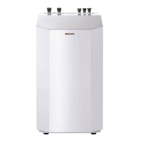
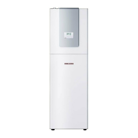
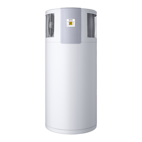
The fully wired appliance enables DHW to be supplied efficiently
to several draw-off points using renewable energy. The appliance
extracts heat from the intake air. This heat is used to heat up the
water in the DHW cylinder with added electric power. The amount
of electric energy and time required to heat up the DHW depend
on the temperature of the air drawn in. When the air intake tem-
perature drops, the appliance output is reduced and the heat-up
time is extended.
The appliance is designed for indoor installation. The choice of
air intake and discharge on the side or top offers flexibility with
regard to possible installation sites. Accessories are required for
the vertical air intake and/or air discharge.
The appliance can be installed as a recirculation air appliance, thus
making efficient use of any available waste heat from freezers or
other heat sources, for example. Alternatively, air ducts can be
connected to use outdoor air as a heat source or to draw in air
from another room.
The ambient air can be cooled down by between 1°C and 3°C as a
result of heat extraction in the installation room or the room from
which the air is drawn. The appliance also extracts moisture from
the air, which turns into condensate. The condensate is removed
from the appliance via the condensate drain.
The appliance has an electronic control unit with LC display. You
can select the available amount of mixed water at a temperature
of 40 °C, for example. The electronic control unit makes energy
saving adjustments easier. Subject to the power supply and user
draw-off patterns, the water is heated automatically to the se-
lected set temperature.
When the air intake temperature drops, the appliance output is
reduced and the heat-up time is extended. If the value falls below
the heat pump's lower application limit, e.g. where outdoor air is
drawn in, the electric emergency/booster heater takes over DHW
heating.
External signal transmitters can be integrated via the built-in con-
tact input, e.g. a photovoltaic system to make use of solar power
generated on site.
When a hot water draw-off point is opened, the hot DHW is pushed
out of the appliance by the inflow of cold water.
The heat pump drive unit is fitted in the upper section of the ap-
pliance. The DHW cylinder is located in the lower section of the
appliance. To protect against corrosion, the DHW cylinder is coated
internally with special enamel and is additionally equipped with
an impressed current anode.
!
Material losses
If you disconnect the appliance from the power supply, it
is no longer protected against frost or corrosion.
Never interrupt the power supply to the appliance.
!
Material losses
If outdoor air is used as a heat source when outside tem-
peratures are low, condensate may form on the appliance
if the relative humidity is unusually high, i.e. in excess
of 75% and with a room temperature of 22°C. Such
high relative humidity levels will damage the fabric of the
building and must be prevented by ventilation.
3.1 Heat pump operating principle
A closed circuit within the appliance contains refrigerant (see
"Specification/Data table"). This refrigerant evaporates at low
temperatures.
In the evaporator, which extracts heat from the air drawn in, the
refrigerant changes from a liquid into a gaseous state. A com-
pressor draws in the gaseous refrigerant and compresses it. This
increase in pressure raises the refrigerant temperature. That re-
quires electrical energy. The energy (motor heat) is not lost, but
reaches the downstream condenser together with the compressed
refrigerant. There, the refrigerant indirectly transfers heat to the
DHW cylinder. An expansion valve then reduces the still prevalent
pressure and the cycle starts again.
If a compressor is required, the appliance does not start the
compressor immediately; only once the fan's initial runtime has
elapsed. During the fan's initial runtime the appliance checks if all
the conditions required to start the compressor have been met.


