Stienen B.E. KL-6500 User manual
USER MANUAL
KL-6500 (-i) CENTRAL COMPUTER
NL
©Stienen BE / KL-6500-G-NL01000
KL-6500

Shut down power before opening the central computer!
The central computer contains exposed live parts!
Only to be opened by authorized personnel!
WARNING
Although utmost care has been given to the quality of this equipment during the design and manufacturing stages,
technical malfunctions can never be ruled out. The user should ensure that an adequate alarm system
and/or emergency provisions is/are in place to prevent any technical failure of the equipment and
peripheral facilities leading to danger to people, animals or property.
IN THE EVENT OF AN EMERGENCY, NOTE DOWN THE FOLLOWING
●Installer settings.
●Circumstances in which the emergency occurred
●Possible causes
●Software version number
If you have any questions, please contact our Customer Service Department. Be sure to have all necessary data
at hand. To ensure a speedy solution to the malfunction, and to avoid any misunderstandings, it is advisable to
note down the cause and the circumstances in which the malfunction occurred before contacting us.
No part of this document may be reproduced or transmitted in any form or by any means, electronic or
mechanical, for any purpose, without the express written permission of Stienen BE (www.StienenBE.com)
Stienen BE accepts no liability for the contents of this manual and explicitly waives all implicit guarantees of
marketability or fitness for a certain use. Stienen BE also reserves the right to improve or change this manual
without being under the obligation to inform any person or organisation of any such improvement or change.
Stienen BE cannot be held liable for any damage, loss or injury resulting from improper use or from use not in
accordance with the instructions in this manual.

Page 3 of 30
OPERATION 4
Changing languages 4
Login 4
Control keys 4
Confirm change 5
Led bar 5
Room bar 5
I/O terminal numbers 5
MAIN MENU 6
Overview screen 6
MANAGEMENT 8
Room 8
Central 8
ROOM CONTROLLER (KLD-100) 9
Room ventilation 9
Inlet flap 11
Room heating 12
Inlet heating 14
Floor heating 15
Cooling 17
Alarm 18
CENTRAL CONTROLLERS (KLC-100) 21
Central ventilation 21
Central heating 22
Central inlet flap 23
Pressure measurement 24
ALARMS 25
Alarm status 25
Alarm history 26
Communication alarm 26
SYSTEM 27
System 27
Device 27
Date and time 28
Remote control 28
MAINTENANCE AND INSPECTION 30
Page 4 of 30
OPERATION
CHANGING LANGUAGES
Languages present:
ENG
NLD
DEU
FRA
RUS
POL
HUN
SPA
CES
TUR
ZHO
JAP
Back
Next
: select next language (see also “
System”, page 27).
: select previous language.
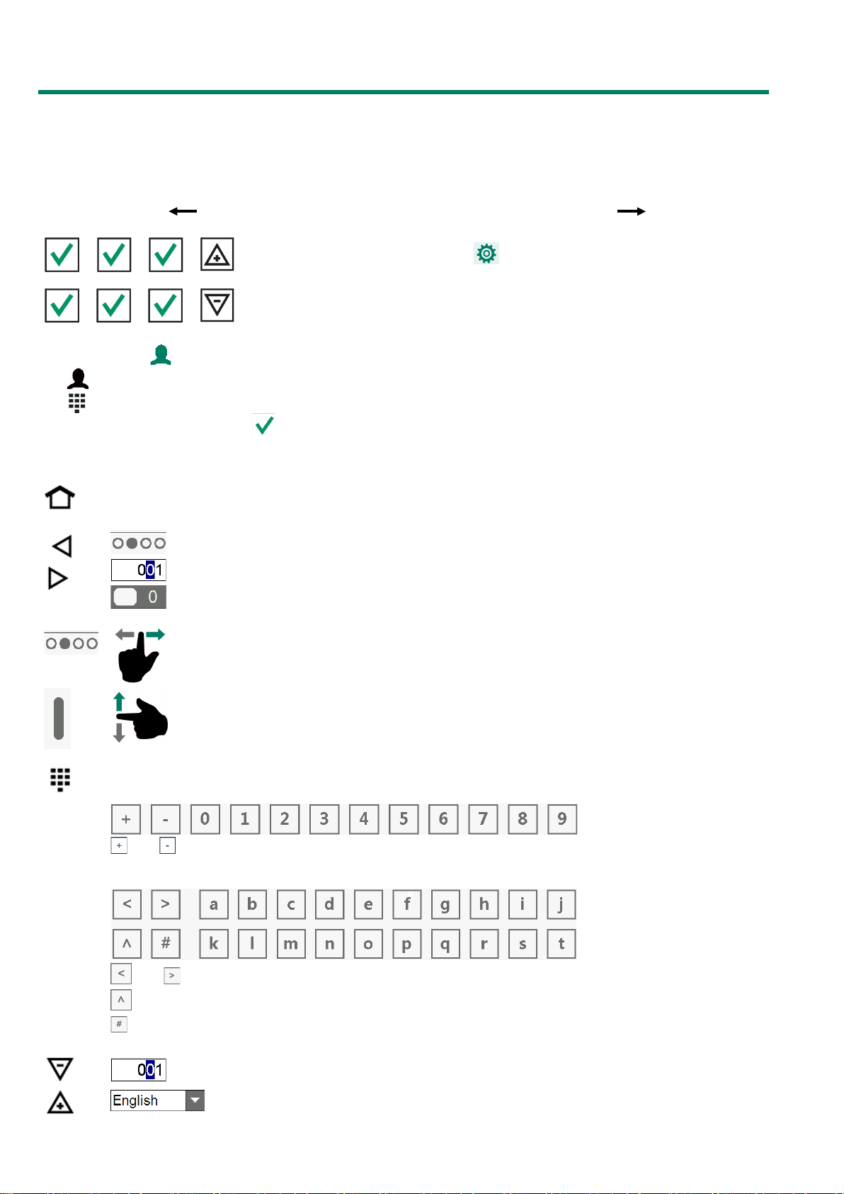
LOGIN
Tap : open login screen.
Tap : open numeric keypad.
Enter the access code and touch .
CONTROL KEYS
: return to the overview screen (HOME).
: select next/previous screen.
: select input position.
: select an option.
: next/previous screen.
: scroll down/up (scroll bar on the right).
If this symbol is lit, tap it to display one the following virtual keyboards.
Set numeric value:
and : change the symbol of a value.
Alphanumeric:
and : choose other characters.
: toggle between lowercase and uppercase letters.
: switch to digits and alternative characters.
: decrease/increase value.
: select an option from an option box.

Page 5 of 30
: undo an option/selection in edit mode.
: confirm an option/selection in edit mode.
: add a breakpoint to or remove it from a list (curve, timer).
: if a setting is followed by the “Link” symbol, use this link to access another screen. The upper
right-hand corner of the “follow-up screen” will then show the “Link back” symbol.
CONFIRM CHANGE
Some important settings can only be changed if the change has been
confirmed. A pop
-up window will show to confirm your change.
LED BAR
Blue
permanently lit:
device not in use
Green
permanently lit:
no alarm
Yellow
permanently lit:
alarm, alarm delay time
has not elapsed
Red
permanently lit:
alarm
flashing at a regular
frequency:
main alarm switched off.
flashing irregularly:
alarm switched off temporarily.
ROOM BAR
Room status:
Room in operation,
no alarm.
Alarm, alarm delay
active.
Alarm, alarm
relay in.
Room out of
operation.
Room heating
status
Heating off
Heating on
Room address
Room name
Room temperature
Room ventilation
Number of animals in the room
Growth curve day number
I/O TERMINAL NUMBERS
I/O type Letter
Serial
number
Explanation
0-10V output A 1-99 Analogue output with a range of 0-10V or 10-0V.
Relay output B 1-99
Relay contact output (this does not include: alarm relay,
digital outputs etc.)
Temperature sensor K 1-99
This includes all types of temperature sensor fitted with 10K
NTC resistors (N10B, BV10B etc.)
0-10V inputs L 1-99
Analogue input with a measuring range of 0-10V. To connect
components such as measuring sensors (RH, pressure, CO2
etc.)
Digital input M 1-99 This includes measuring fans, counter contacts etc.
Page 6 of 30
MAIN MENU
KL-6500
KLD-100
KLC-100
House temperature summary
Outside temperature summary
Summary of outside temperature
Management
Room heating operating hours
Air scrubber pressure summary
Room heating operating hours
NH3 summary
Reset min./max. table
Reset min./max. table
Ventilation
Inlet flap
Room heating
Room
Inlet heating
Room heating
Cooling
Alarm
Central exhaust
Central heating
Central
Central inlet flap
Pressure
Ammonia
Alarm
Alarm Status
Alarm
Latest 5 alarms
Communication alarm
System
Device
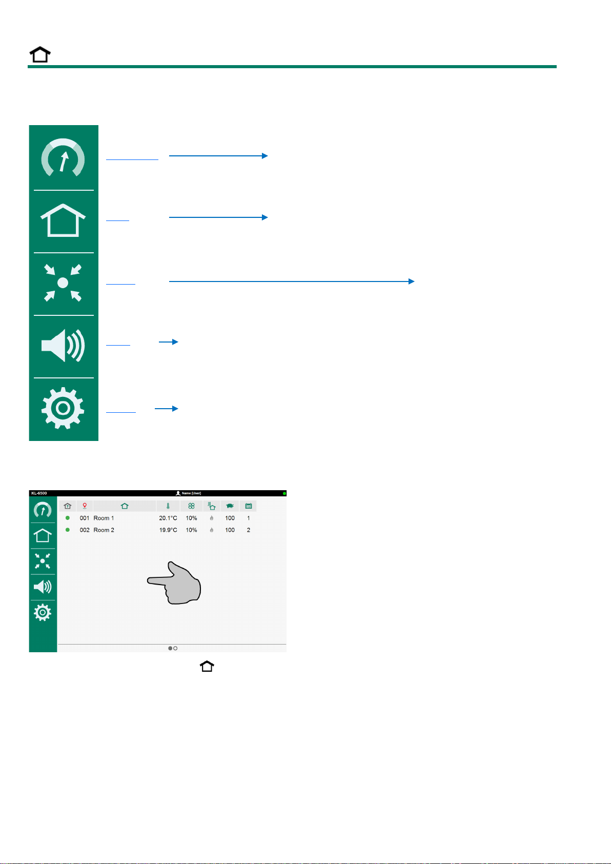
OVERVIEW SCREEN
Tap the “Screen” or tap the “Home” key: this brings up the main menu.

Page 7 of 30
ADD MENU ITEM TO FAVOURITES BAR
•Select the screen that should be added to the favourites bar.
•Touch the menu item icon until the “add” window is displayed.
•Tap (OK) to add the menu item to the favourites bar.
REMOVE MENU ITEM FROM FAVOURITES BAR
•Touch the icon of the menu item that you would like to remove until you see the “delete” window.
•Tap (OK) in order to remove the menu item from your favourites bar.
Favourites bar
Page 8 of 30
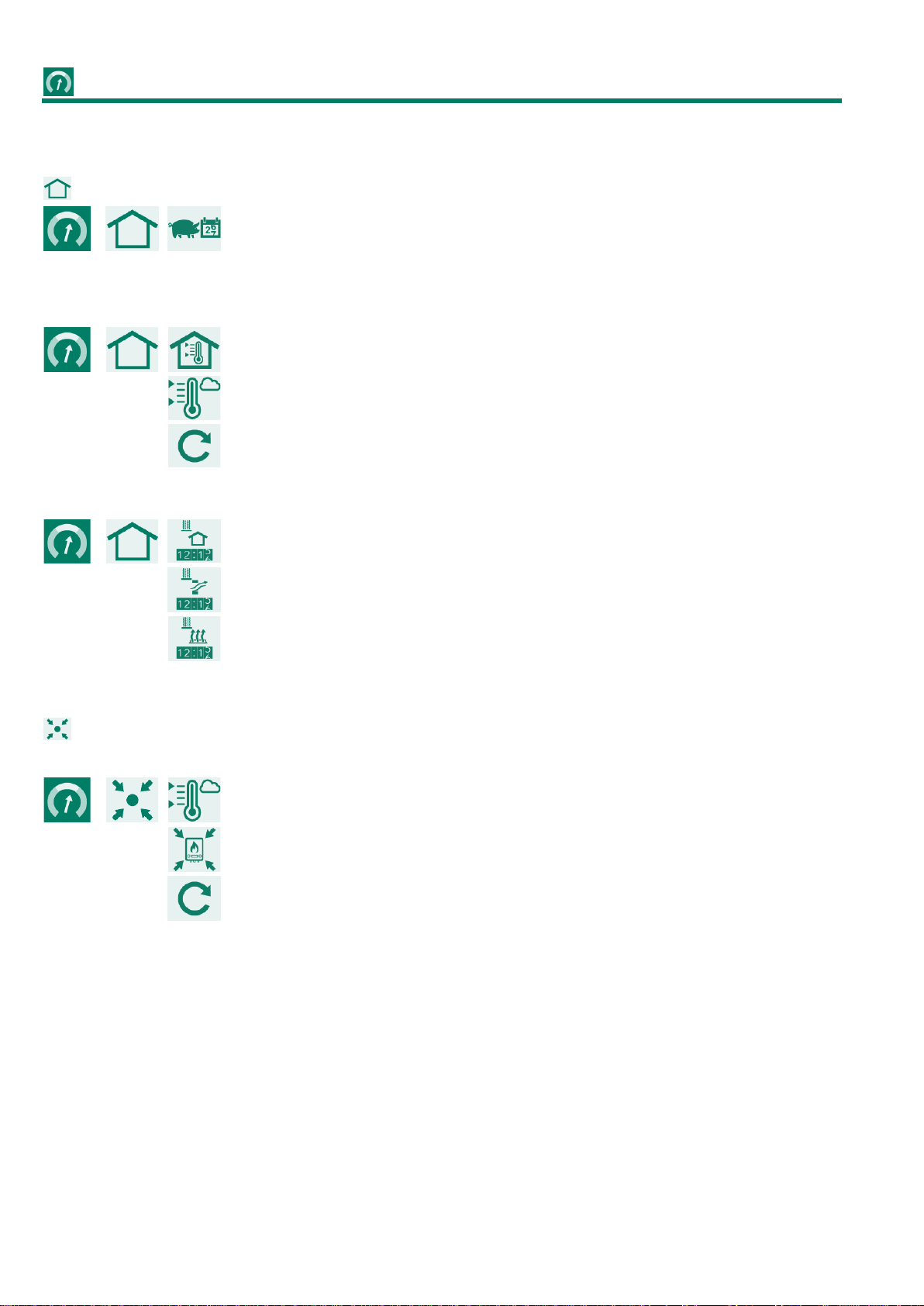
MANAGEMENT
ROOM
Animal data:
•Curve day number.
•Current number of animals in the house
MIN./MAX. TABLE
Min./Max. house temperature table.
Min./Max. outside temperature table.
Reset min./max. value today (of all tables).
HOURS COUNTER
Room heating operating hours*.
Inlet heating operating hours*.
Floor heating operating hours*.
CENTRAL
HEATING
Min./Max. outside temperature table.
Central heating operating hours*.
Reset min./max. value today (of all tables).
*The operating hours can be cleared by setting the slider behind “Clear operating hours” to “1”.
Page 9 of 30
ROOM CONTROLLER (KLD-100)
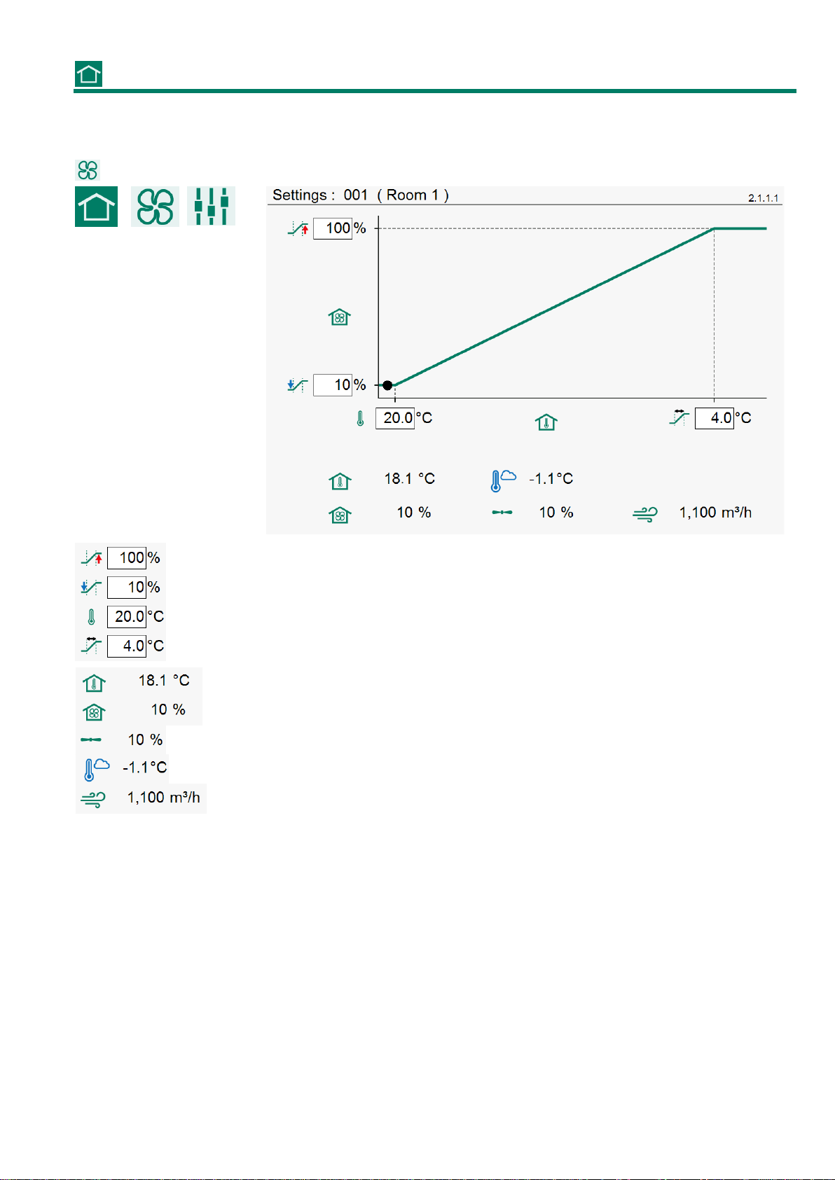
ROOM VENTILATION
Maximum ventilation (with the room temperature + bandwidth settings chosen)
Minimum ventilation (with the room temperature setting chosen)
Room temperature setting
Bandwidth
C
urrent room temperature
Calculated ventilation
Current ventilation
Current outside temperature
Current ventilation capacity
Page 10 of 30
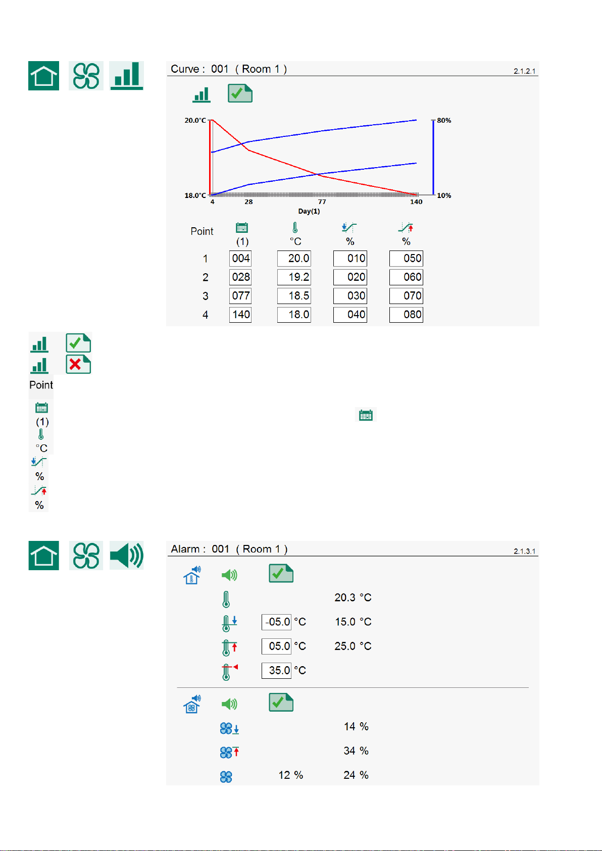
ROOM CURVE (TEMPERATURE, MINIMUM VENTILATION, MAXIMUM VENTILATION)
Room temperature curve “On”
Room
temperature curve “Off”
Breakpoint number
Breakpoint day number (the value under
is the current day number)
Room temperature for the preset day number.
Minimum ventilation for the preset day number.
Maximum ventilation for the preset day
number.
ROOM ALARM (TEMPERATURE, VENTILATION)

Page 11 of 30
Room temperature alarm “On”
Room temperature alarm “Off”
Current room temperature alarm
Minimum room temperature alarm limit
Maximum room temperature alarm limit
Absolute room temp
erature alarm limit
Ventilation alarm “On”
Ventilation alarm “Off”
Minimum ventilation limit
Maximum ventilation limit
Calculated and measured ventilation
The ventilation alarm only shows if a measuring fan has been installed.
INLET FLAP
Current ventilation
Current valve position
The flap controls on the basis of ventilation. Normally, the opening of the flap is directly proportional to the flap
position as a %. The air displacement caused by this flap, however, is not directly proportional to the flap
position. The characteristic can be used to obtain a better flap position/air displacement ratio.

Page 12 of 30
ROOM HEATING
•Room heating temperature setting
(temperature difference relative to
room temperature setting, see screen 2.1.1.x page 9).
•Calculated room heating temperature.
•
Calculated room heating temperature from curve.
•Current room temperature.
•The room heating status is On (“On/Off heating”).
•Current room temperature.
•
Room heating status (heating is: “Off”).
•Current heating capacity of room heating (“controlled heating”)
•Current room temperature.
•
Room heating status (heating is: “On”).
•Current heating capacity of room heating (“controlled heating”)
ROOM HEATING CURVE
Room heating curve “On”

Page 13 of 30
Room heating curve “Off”
Breakpoint number
Breakpoint day number (the value under
is the current day number)
Room heating temperature for the preset day number.
The day numbers can only be set in the “Room curve”.
Page 14 of 30
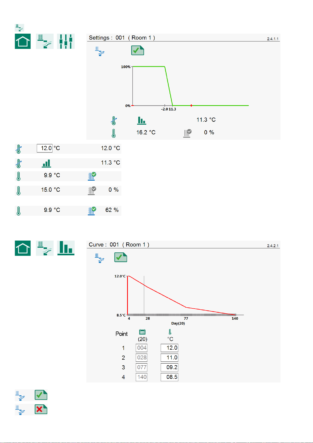
INLET HEATING
•Inlet temperature setting
•Calculated inlet temperature
•
Inlet temperature setting from curve
•Current inlet temperature
•Inlet heating status (“On/Off heating”)
•Current inlet temperature
•
Inlet heating status (heating is: “Off”)
•Current heating capacity (“controlled heating”)
•Current inlet temperature
•
Inlet heating status (heating is: “On”)
•Current heating capacity (“controlled heating”)
INLET HEATING CURVE
Inlet temperature curve “On”
Inlet temperature curve “Off”

Page 15 of 30
Breakpoint number
Breakpoint day number (the value under
is the current day number)
Inlet temperature for the preset day number.
The day numbers can only be set in the “Room curve”.
INLET HEATING ALARM
Inlet temperature alarm “On”
Inlet temperature alarm “Off”
Current inlet temperature alarm
Minimum inlet temperature alarm limit
Maximum inlet temperature alarm limit
Absolute inlet temperature alarm limit
FLOOR HEATING
•Floor temperature setting
•Calculated floor temperature
•
Floor temperature setting from curve
Page 16 of 30
•
Current floor temperature
•Floor heating status (“On/Off heating”)
•Current floor temperature
•
Floor heating status (heating is: “Off”)
•Current heating capacity (“controlled heating”)
•Current floor temperature
•
Floor heating status (heating is: “On”)
•Current heating capacity (“controlled heating”)
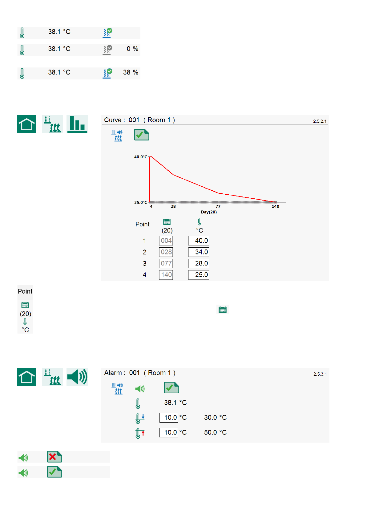
FLOOR HEATING CURVE
Breakpoint number
Breakpoint day number (the value under
is the current day number)
Room temperature for the preset day number.
The day numbers can only be set in the “Room curve”.
FLOOR HEATING ALARM
Floor heating alarm “On”
Floor heating alarm “Off”

Page 17 of 30
Current floor heating temperature
Minimum flo
or heating alarm limit
Maximum floor heating alarm limit
COOLING
Cooling “On”
Cooling “Off”
•Cooling temperature setting
•Calculated cooling temperature
•
Cooling temperature setting from curve
•Current cooling temperature
•Cooling status “On”
•Current cooling temperature
•Cooling status “Off”

Page 18 of 30
COOLING CURVE
Cooling curve “On”
Cooling curve “Off”
Breakpoint number
Breakpoint day number (the value under
is the current day number)
Cooling temperature fo
r the preset day number.
The day numbers can only be set in the “Room curve”.
ALARM
Page 19 of 30
Main alarm on/off
Alarm temporarily off
Siren test
MAIN ALARM
If the main alarm is off, the LED bar will flash red, at a regular frequency. No alarms will be generated then. See
also LED bar page 5.
ALARM TEMPORARILY OFF
Temporarily disabling the main alarm (siren). Hardware alarms cannot be switched off temporarily. The main
alarm is switched off for 30 minutes (the LED bar will flash irregularly). The main alarm is switched on
automatically again after 30 minutes. The alarm relay will de-energize again, causing an alarm, if the cause of
the alarm has not been removed.
SIREN TEST
Test the alarm relay (siren). The alarm relay (siren) is switched on for 120 seconds.
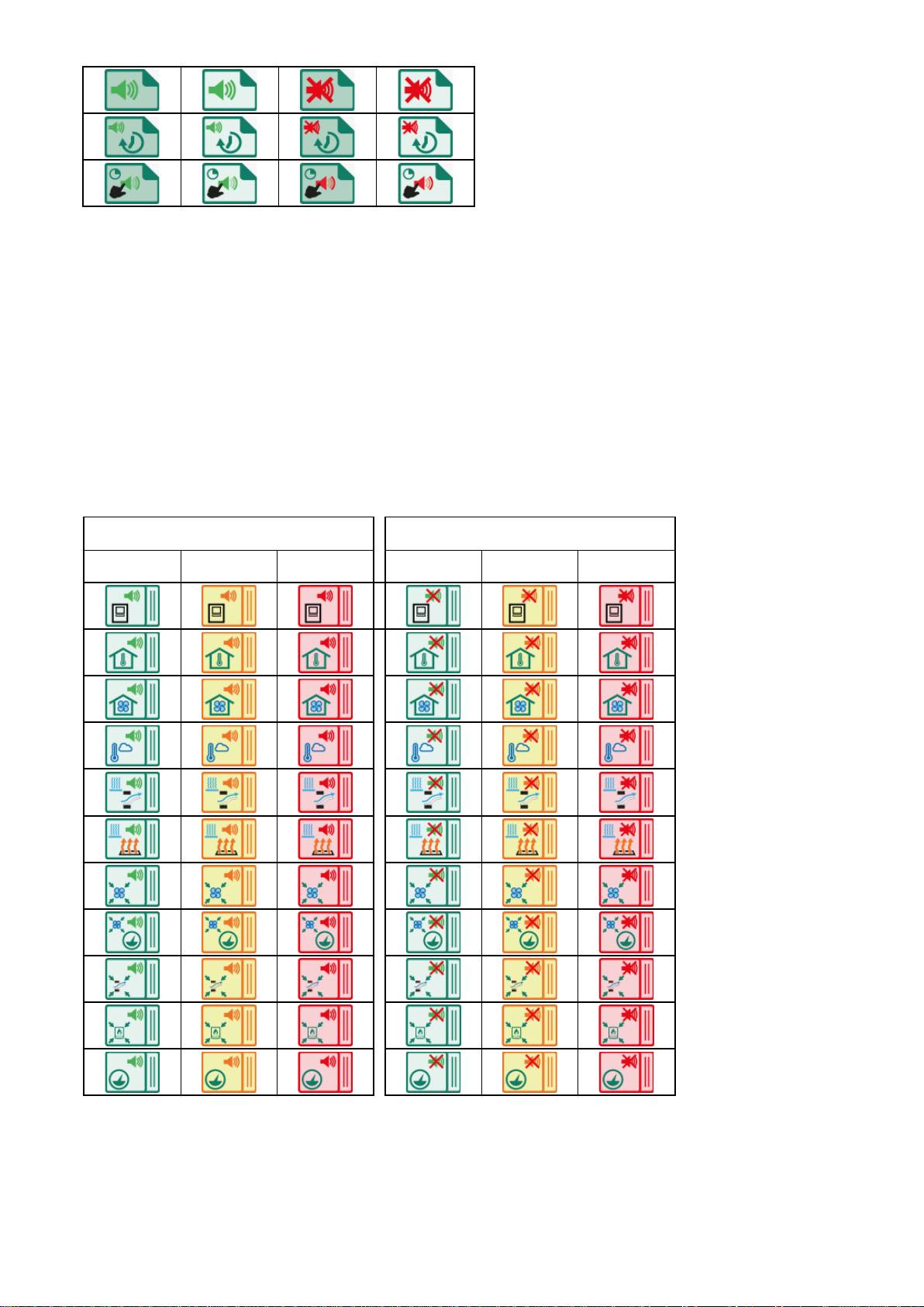
ALARM STATUS
Alarm on
Alarm off
(alarm relay is NOT switched on)
No alarm
Alarm
in the making
Alarm
(alarm relay in)
No alarm
Alarm
in the making
Alarm
Device
Room temperature
Ventilation
Outside temperature
Inlet heating
Room heating
Central ventilation
Central ventilation
pressure control
Centr
al inlet flap
Central heating
Pressure measurement

Page 20 of 30
ALARM CODES
Module not found
Jumper A on RTCPU is in its lower position, set jumper A to its upper position or else the changes will
not be saved.
Communication er
ror between devices.
Communication error with WEB
-485 (FramConnect)
No data from climate controllers
No ventilation (measurement = 0%).
Ventilation too low
Ventilation too high
No outside temperature sensor
Temperature sensor faulty
Pressure sensor faulty
NH3 sensor faulty
Temperature too low
Temperature too high
Pressure too low
Pressure too high
NH3 too low
NH3 too high
If no icon is linked to the alarm code, the alarm code will
be shown in a red box (please contact your
supplier to report this alarm situation in order to make sure that this alarm code will be displayed
correctly in the future).
Note
NEVER FORGET TO SWITCH AN ALARM “ON” AGAIN AFTER IT WAS SWITCHED OFF (e.g. in
order to remedy a malfunction). Failing to switch the alarm back on may have adverse effects for
people, animals, equipment or property.
Preferably use the alarm temporarily off function to remedy a malfunction.
1
This manual suits for next models
1
Table of contents
Other Stienen B.E. Desktop manuals


