Stierius UNIVERSAL User manual
BODO STIER Hydrotechnik GmbH
Gutenbergstr. 2-4
D-78727 Oberndorf /Neckar
Telefon +49 (0)7423 3321
+49 (0)7423 4711 (Technical Hotline)
Fax +49 (0)7423 82422
Internet: http://www.stierius.com
Owner's Manual
Brake Service Device
Typ
UNIVERSAL
(pneumatic)
In addition to the items stated in the Owner's Manual, the
following safety advice must be followed:
1. Always follow this safety advice for risk-free operation.
2. Always visually check the device for damage before use. Do not use faulty devices;
have them repaired by an authorized professional.
3. Only use the device within the scope of the present Owner's Manual (see
"Preparing for use").
4. The device is exclusively designed for filling hydraulic clutch and brake systems with
pure glycol-based BRAKE FLUID. OTHER MEDIA (mineral oil, fuels, cleaning agents,
etc.) WILL CAUSE PERMANENT DAMAGE TO THE DEVICE!
5. Use personal protective equipment as per the specifications in the safety advice for the
filling medium. In case of contact with the filling medium, perform the actions described
in the safety advice.
6. Clean devices with external soiling. No residues of flammable liquids must remain on
the housing.
7. Do not clean the device with a pressure cleaner!
8. Do not place cloths soaked in oil, fuel or solvent on the device.
9. Use only matching accessories (e.g., bleeding adapters) as per the manufacturer's
specifications (see also the list of adapters [Adapterliste] on the Internet at
www.stierius.com).
10. Observe the respective vehicle manufacturer's instructions!
To ensure the reliability and safety of the device, we recommend having maintenance
performed regularly on the device by qualified staff.
To ensure environmentally-compatible disposal of the used medium, we recommend
using a closed brake fluid disposal system.
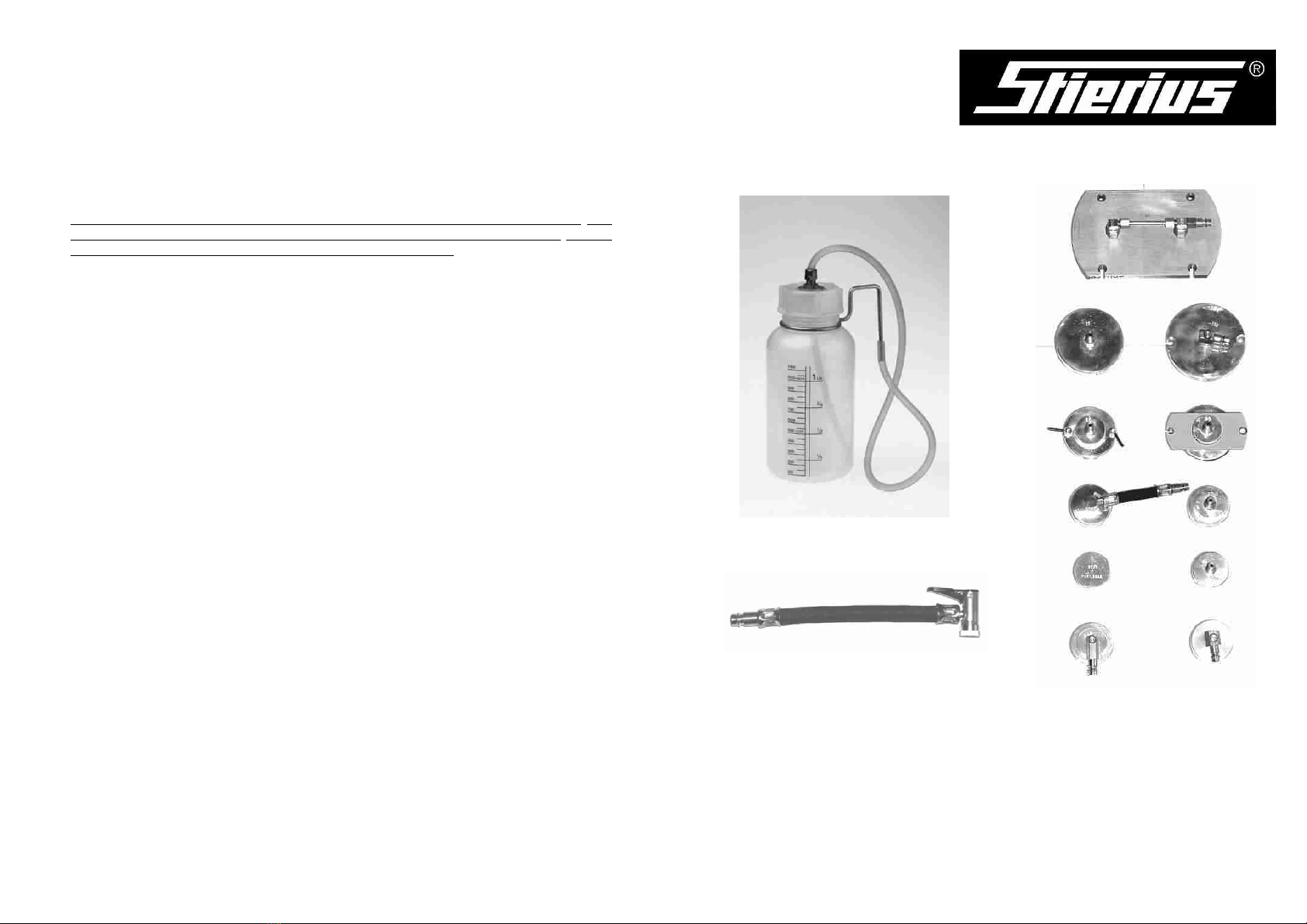
Accessories
Catchment container
(Clutch) bleeder hose no. 67
Various adapters
A vehicle-specific application list can be viewed on
www.stierius.com.

Technical data:
460 mm ---
300 mm ---
300 mm ---
Height:
Width:
Depth:
Weight empty: 6,5 kg ---
Content: 5 l0-3,5 bar
Flow rate: approx. 60 l/h 0-4 bar
(at 2.5 bar dynamic pressure/2.0 bar
delivery pressure)0-6,5 bar
Hose length: approx. 3,5 m
Control range:
Operating pressure display:
Standby pressure:
Operating temperature: 0º-45ºC
We expressly reserve the right to make changes for technical reasons, including
design changes.
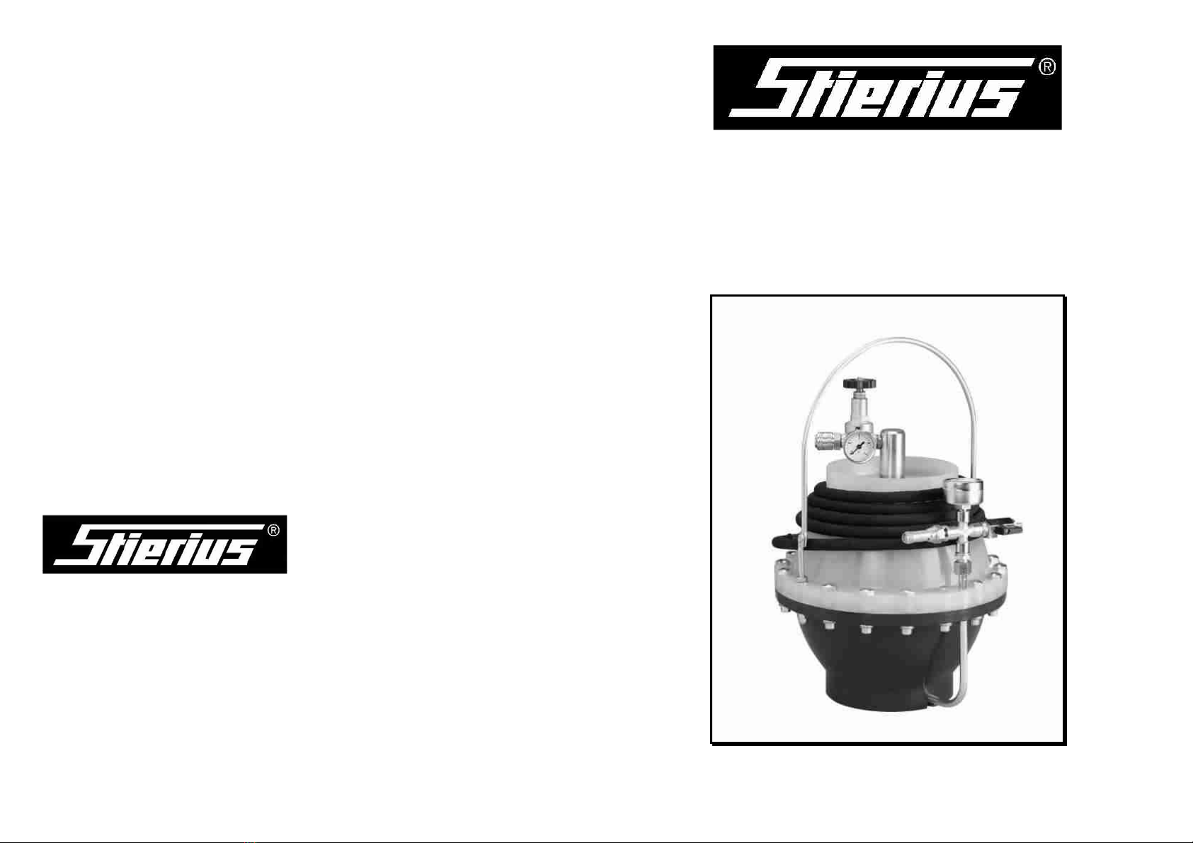
Brake Service Device
UNIVERSAL
Note:
The UNIVERSAL Brake Service Device reflects the state-of-art in the field of hydraulic brake
system and clutch actuator maintenance. It also meets the requirement for the work being
performed by a single mechanic (observe the vehicle manufacturer's work instructions).
Suitable for all ABS systems and hydraulic clutches.
The device has a very robust design and can be deployed universally. Handling of the device
is so simple that mechanics do not need special training.
However, every mechanic who will be working with this device must be introduced to the
device and instructions on the use of the device must be provided in the form of the
operating instructions. The 5 liter brake fluid tank means that several brake fluid changes can
be performed without refilling the device.
Important!
Soiled brake fluid or water content in the brake fluid can cause the hydraulic brake system to
fail. For this reason, use only brake fluid from brake fluid containers with an original fill.
The hygroscopic properties of brake fluid mean that it absorbs moisture from the ambient air.
Moisture reduces the boiling point of the brake fluid to a dangerous extent. Braking causes
high temperatures in the brake system; in a brake system contaminated with moisture, this
cause boiling bubbles in the brake fluid that can make further braking actions impossible.
Corrosion within the brake system is caused by electrolytic actions of brake fluid with water
content. Boiling bubbles and air inclusions already result in corrosion as the air inclusions
contain oxygen.
It is thus recommended to replace the brake fluid in hydraulic brake systems every 15,000
km.
When changing the brake fluid in hydraulic systems, always push the used brake fluid out of
the system with the new brake fluid.
Condition at delivery/preparing for use
In its condition at delivery, the packaging contains the following parts:
1 Brake Service Device, comprising of:
Device with handle, locking piece with reducer, filling hose
1 Owner's Manual
1 adapter no. 20
1 catchment container (optional)
Check the device for transport damage on unpacking. Report any transport damage to the
appropriate freight forwarder without delay.
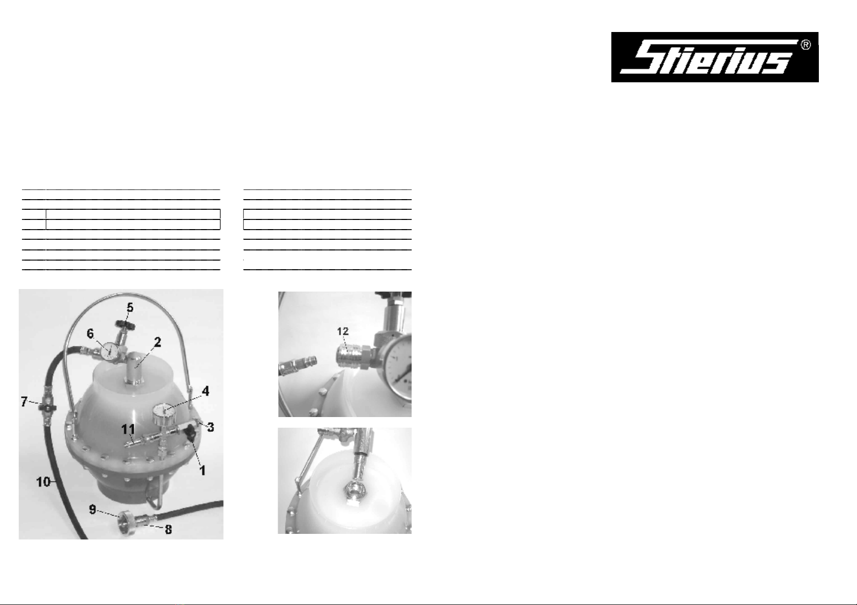
Device description (Fig.):
Part Part designation Part Part designation
10 Filling hose, complete
11 Safety valve
12 Sealing cap coupling
13
14
16
17
1 Shut-off valve of air filling valve
2 Sealing cap complete with pressure reducer
3 Nozzle for air filling
4 Standby pressure gauge (ÿ50)
5 Spindle (handwheel) for pressure reducer
6 Operating pressure gauge (ÿ40)
7 Shut-off valve for filling hose
8 Filling hose coupling
9 Adapter (Fig: no. 20)
<=Fig. 1
Fig. 2=>
Fig. 3=>
We expressly reserve the right to make changes for technical reasons, including design
changes.
Practical advice and tips for effective bleeding of a hydraulic brake or clutch system
After the UNIVERSAL Brake Service Device has been connected to the compensating tank
using a connecting cover (adapter), the procedure for bleeding the system or changing the
brake fluid can begin.
þ Perform bleeding as per the vehicle manufacturer's specifications.
þ Open each bleeding valve until clear, bubble-free brake fluid escapes.
þ To make it easier to check the escaping brake fluid (cleanliness) and precisely measure the
used brake fluid, we recommend the use of our catchment container with a graduation.
þ When completely refilling the brake system, it is useful to open all bleeder screws.The
brake fluid pushes the air out. Because the bleeder screws are open, the air takes the
path of least resistance and immediately escapes without counterpressure and without
any risk of mixing. When clear, clean brake fluid starts to escape at the bleeder screw,
manually screw in the bleeder screw wheel by wheel. After completing this work step,
tighten the bleeder screw again.
þ We recommend slowly and fully actuating the brake or clutch pedal a number of times
during the bleeding and brake fluid change procedure; this guarantees that brake fluid flows
into the annular spaces between the primary and secondary sleeves and that any remaining
air bubbles in the cylinder are loosened.
þ In case of brake systems with a fixed caliper, a greater liquid flushing volume is required for
changing the brake fluid in order to ensure that the brake fluid can be appropriately changed
in those parts of the housing cover that do not have a direct flow. Note that several bleeder
valves can exist in fixed calipers. All bleeder valves must be bled in succession.
þ For vehicles with a load-driven braking force regulator, the hydraulic passageway to the
wheel brakes connected to the compensator may be blocked if the axles are relieved
(vehicle is on a 2-pillar lifting platform).To ensure trouble-free bleeding, or trouble-free
replacement of the brake fluid, the axles should be loaded. Observe the data of the
respective vehicle manufacturer.
þ Clutch bleeding hose no. 67 is recommended for bleeding and filling hydraulic clutch
systems. This hose is connected to and locked onto the bleeder valve on the master
cylinder by means of a push-on, lever-action nipple. The used brake fluid is vacuumed out
of the compensating tank prior to this. Following this, the system is bled and filled from the
bottom upward.
Further bleeding adapters are available for all vehicles.

When does the device need to be refilled?
If the pressure at the operating pressure gauge (6) drops to zero, although the standby pressure
(4) is greater than 1 bar, the brake fluid tank is empty => Refilling the device, see
"Preparing for use" The air tank is designed to allow the complete brake fluid (5 liters) to be
extracted at a pressure of at least 1.5 bar. There is typically no need to fill up with compressed
air.
Storage
In case of extended periods without use, the compressed air can be released. When you need to
use the device again, fill with compressed air as per step 7 under "Preparing for use" or refill as
described beginning with step 1 under "Preparing for use".
Safety
The owner must call in an authorized expert to perform tests as per Section 10 BetrSichV
(German Industrial Safety Regulations).
Repairing the device
Repairs to the device must be performed by an authorized customer service agent!
Only ship in suitable packing! STIERIUS accepts no liability for any transport damage. Shipping
costs to be paid by the sender.
Disposal
The device can be returned to the manufacturer/sales partner (shipping and transport costs to
be paid by the sender); or it must be disposed of taking national and local waste disposal
regulations into account.
Preparing for use:
1. IMPORTANT! Open the shut-off valve (1) at the air filling valve (longitudinal position:
air escapes fully from the air tank) and leave it open.
2. Disconnect the filling hose (10) from the sealing cap coupling (12) (Fig. 2).
3. Unscrew and remove the sealing cap from the device (Fig. 3). NEVER OPEN AT
HEXAGON NUT SW41! (See "CAUTION! Never open the upper part of the
device!")
4. Slowly fill the device with fresh brake fluid up to the top edge of the fitting. Allow the
fluid in the device to degasify for longer than 10 minutes.
5. Check the fill level; fill up again if needed; screw in the sealing cap (2) (hand-tight
to the stop, NO FARTHER!).
6. Connect the filling hose (10) to the sealing cap.
7. Fill the device with compressed air via the air filling valve (3) until the standby
pressure gauge (4) shows 6.5 bar. Then close the shut-off valve (1) (transverse
position).
8. Turn in the handwheel (5) on the pressure reducer up to the lock nut (the operating
pressure gauge (6) then shows the preset pressure; factory setting: 2 bar).
9. Connect an adapter or nozzle to the filling hose coupling (8); open the shut-off valve
(7) for the filling hose (longitudinal position) and allow the brake fluid to run into a
suitable container until it is bubble free (approx. 1/4 liter). The device is now ready for
use.
10. Mount a suitable adapter on the master cylinder compensating tank and connect
the filling hose with quick coupling (8) to the plug-in nipple on the bleeding adapter.
Now perform bleeding or the brake fluid change as required. Note the approach
specified by the vehicle manufacturer in question; this applies in particular to vehicles
with an ABS system and/or load-driven braking force regulators.
11. Depressurize the filling hose after the bleeding action; to do so: Shut off the shut-off
valve on the filling hose (7) and relieve the pressure via the bleeder nipple on one
wheel cylinder (catchment container!). This means that the filling hose coupling (8) can
be disconnected from the adapter without spilling brake fluid.
12. Mount the original cap on the compensating tank again.
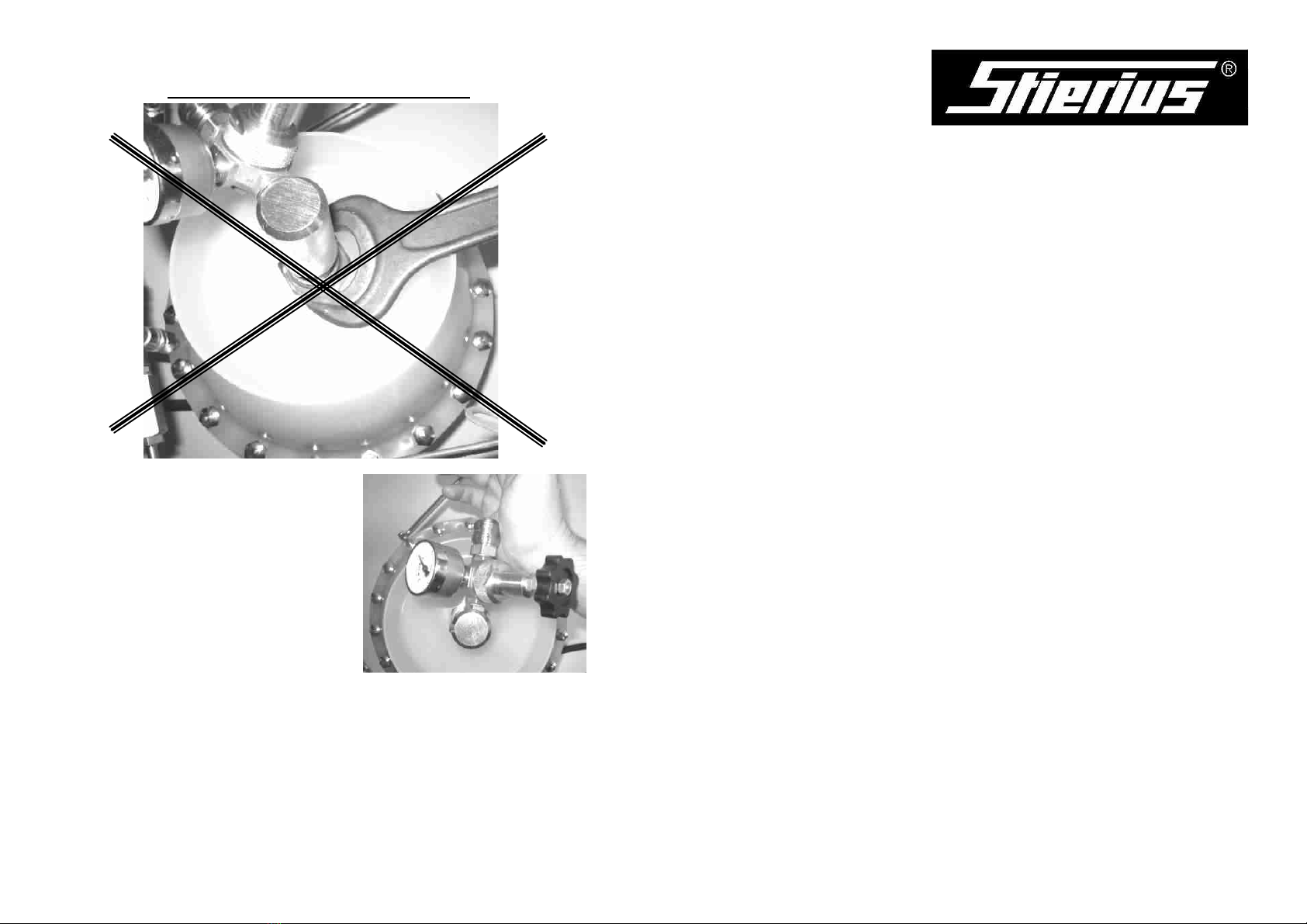
ATTENTION!
NEVER OPEN THE DEVICE UPPER PART
When closing the device, only hand-tighten
the device upper part up to the stop!
To open (relieve the compressed air; see step 1
under "Preparing for use"), tap lightly with the
ball of your hand in counterclockwise direction.
Never push down the separating diaphragm with
objects of any kind (screwdrivers, wire, etc.); this
happens automatically on filling the device!
Never fill the device with compressed air via the upper part or filling hose!
Tip: Fill the device with warm brake fluid (22 °C room temperature) if possible;
if the brake fluid is cold (=higher viscosity), allow the device to degasify for
longer before filling with compressed air (see step 4 under "Preparing for use").
General instructions
After bleeding or changing the brake fluid, if you notice that the brake or clutch pedal
actuation path is too long, or that pressure build-up is too "soft", you then need to bleed
the brake or clutch system again after firmly actuating the brake or clutch system multiple
times.
Setting the correct operating pressure
The pressure reducer (5) is factory set to an operating pressure of 2 bar. This prevents
the compensating tank deforming during bleeding or a brake fluid change via the
compensating tank, thus avoiding the risk of leakage in the secondary sleeve. Bleeding or
a brake fluid change at a lower operating pressure (as required for some vehicle types) is
easily possible; a higher operating pressure is desired in a few exceptional cases.
Lower operating pressure: Shut off the shut-off valve (7) on the filling hose. Turn out the
handwheel (5) on the pressure reducer. Connect the filling hose to the vehicle as
described in step 10 under "Preparing for use". Open the shut-off valve (7) and slowly turn
the handwheel (5) on the pressure reducer until the desired pressure is shown at the
operating pressure gauge (6).
ATTENTION!
After bleeding with a lower or higher operating pressure, be sure to set the
pressure reducer back to 2 bar operating pressure.
Low pressure leak test
The UNIVERSAL Brake Service Device can also be used for low pressure testing of
hydraulic brake systems. The device remains connected to the compensating tank by
means of a bleeder adapter. Note that all bleeder screws must be closed for this. Apply
the device's operating pressure (2 bar) to the brake system. The pressure reducer is
closed by turning the handwheel on the pressure reducer (5) counterclockwise. The
operating pressure shown on the pressure gauge (6) must not drop within 5 minutes. If
the operating pressure drops within the test period, the brake system has a leakage.
Table of contents
Other Stierius Industrial Equipment manuals

Popular Industrial Equipment manuals by other brands


Witt
Witt GP 42 Operation & service manual

VERACHTERT
VERACHTERT PW Series operating manual

SNR
SNR NTN SNOE 200 Series Assembly, servicing and maintenance instructions

schmersal
schmersal AZM201Z-I1-SK-T-1P2PW Instructions for operation

Centa
Centa CENTAX-L Assembly and operating instructions

ABB
ABB HT843322 Operation manual

Numberall
Numberall 250P manual

WPG
WPG FLEXR Series operating instructions

Zimmer
Zimmer DKPS1000 Series Installation and operating instructions

Sure-Feed Engineering
Sure-Feed Engineering SE-900-EI Operations & parts manual

Tektronix
Tektronix IntelliFrame VX1410A instruction manual

ABB
ABB HT576242 Operation manual