Simpro Dumpmaster User manual

User Manual | Simpro Dumpmaster®
Original Instructions | English | v59.0 | December 2019
USER MANUAL
S i m p r o D u m p m a s t e r ®

Copyright © 2019 Simpro Handling Equipment Ltd.
No part of this document may be reproduced or transmitted in any form or by any means,
electronic, mechanical, photocopying, recording, or otherwise, without the written
permission of Simpro Handling Equipment Ltd.
For the purposes of standards compliance and international conformity, this document uses
Système International (SI) units. These may be converted to Imperial units as follows:
1 kilogram (kg) = 2.2 pounds (lb)
1 metre (m) = 1000 millimetres (mm) = 39.37 inches (in) = 3.28 feet (ft) = 1.09 yards (yd)
The following stylistic conventions are used throughout this document:
Text in GREEN indicates a point of interest.
Text in RED indicates a point of warning or a safety hazard.
User Manual | Simpro Dumpmaster®
Original Instructions | English | v59.0 | December 2019 | Page 2

1. Contents
1. Contents....................................................................................................................... 3
2. Product Overview........................................................................................................ 5
2.1 Key features........................................................................................................................... 5
2.2 Construction .......................................................................................................................... 5
2.3 Mechanism ............................................................................................................................ 6
2.4 Safe Lifting Capacity ............................................................................................................6
2.5 Duty cycle.............................................................................................................................. 6
2.6 Intended operational life ..................................................................................................... 7
2.7 Noise emissions ...................................................................................................................... 7
2.8 Environmental restrictions .................................................................................................... 7
2.9 Ingress protection ................................................................................................................. 7
2.10 Notes ...................................................................................................................................... 8
3. Safety Assessment ....................................................................................................... 9
3.1 Safety features ......................................................................................................................9
3.2 Reasonably foreseeable misuse ......................................................................................... 9
3.3 OSH Compliance Specification Guide .............................................................................. 9
3.4 Hazard and Risk Assessment Guide ..................................................................................11
3.5 Safety Norms........................................................................................................................ 17
4. Operating Instructions ............................................................................................... 19
4.1 Before operation................................................................................................................. 19
4.2 Emplacing and removing bins .......................................................................................... 19
4.2.1 Cradle identification..................................................................................................................... 19
4.2.2 EN840 Base-lift Cradle (standard) ............................................................................................... 21
4.2.3 EN840 Comb-lift Cradle................................................................................................................ 21
4.2.4 ANSI Bar-lift Cradle........................................................................................................................ 21
4.2.5 ANSI Bar-lift Cradle with base ...................................................................................................... 22
4.2.6 Trunnion-lift Cradle (DIN9797 Eurobins & Foodcap®)................................................................ 22
4.2.7 Combi-Cradle and Custom Cradle ............................................................................................ 22
4.3 Operation of controls .........................................................................................................23
4.3.1 Control Panel identification ......................................................................................................... 23
4.3.2 Standard Control Panel................................................................................................................ 24
4.3.3 Autocycle Control Panel.............................................................................................................. 24
4.3.4 VSD Control Panel......................................................................................................................... 25
4.3.5 Safety-Monitored Control Panel.................................................................................................. 25

User Manual | Simpro Dumpmaster®
Original Instructions | English | v59.0 | December 2019 | Page 4
5. Care and Maintenance............................................................................................ 27
5.1 Quick Troubleshooting Guide............................................................................................ 27
5.2 Cleaning ..............................................................................................................................28
5.3 Cradle jams ......................................................................................................................... 28
5.4 Electrical System (battery) ................................................................................................. 31
5.4.1 Localisation.................................................................................................................................... 31
5.4.2 Voltmeter ....................................................................................................................................... 31
5.4.3 Battery charging ........................................................................................................................... 31
5.4.4 Batteries and battery care........................................................................................................... 32
5.4.5 Smart charger ............................................................................................................................... 32
5.4.6 Appliance socket.......................................................................................................................... 32
5.4.7 Lockout switch............................................................................................................................... 32
5.4.8 Overload fuse................................................................................... Error! Bookmark not defined.
5.4.9 Solar panel..................................................................................................................................... 33
5.5 Electrical System (3-phase mains) .................................................................................... 34
5.6 Electrical System (1-phase mains) .................................................................................... 35
5.7 Hydraulic System ................................................................................................................. 37
5.7.1 Powerpack .................................................................................................................................... 37
5.7.2 Control valves................................................................................................................................ 37
5.7.3 Lift Ram .......................................................................................................................................... 37
5.7.4 Hydraulic fluid................................................................................................................................ 37
5.7.5 Maintenance................................................................................................................................. 37
5.7.6 Hydraulic system schematic ........................................................................................................ 37
5.8 Safety door and interlock .................................................................................................. 38
5.9 Safety-Monitoring System (PL(d)/PL(e) only) ...................................................................41
6. Assembly, Handling, Transport & Storage................................................................ 43
7. Safety Inspections...................................................................................................... 45
7.1 Pre-inspection checklist ..................................................................................................... 45
7.2 Weekly inspection............................................................................................................... 45
7.3 Monthly inspection .............................................................................................................47
7.4 Annual inspection ............................................................................................................... 49
8. Spare Parts ................................................................................................................. 51
9. Warranty..................................................................................................................... 53
10. EC Declaration of Conformity............................................................................... 55
11. Notes ....................................................................................................................... 56

2.Product Overview
Congratulations on your purchase of a Simpro Dumpmaster bin-tipping machine. The
Dumpmaster is probably the safest, fastest and most reliable bin tipper on the market, and
has been continuously developed over more than thirty years.
The Dumpmaster is very versatile and can be used in numerous applications, ranging from
emptying rubbish bins into skips to pouring food ingredients into mixers. Regardless of the
application, the Dumpmaster has proven to be safe, reliable and
economical to operate, year after year.
2.1 Key features
Key features of the Dumpmaster include:
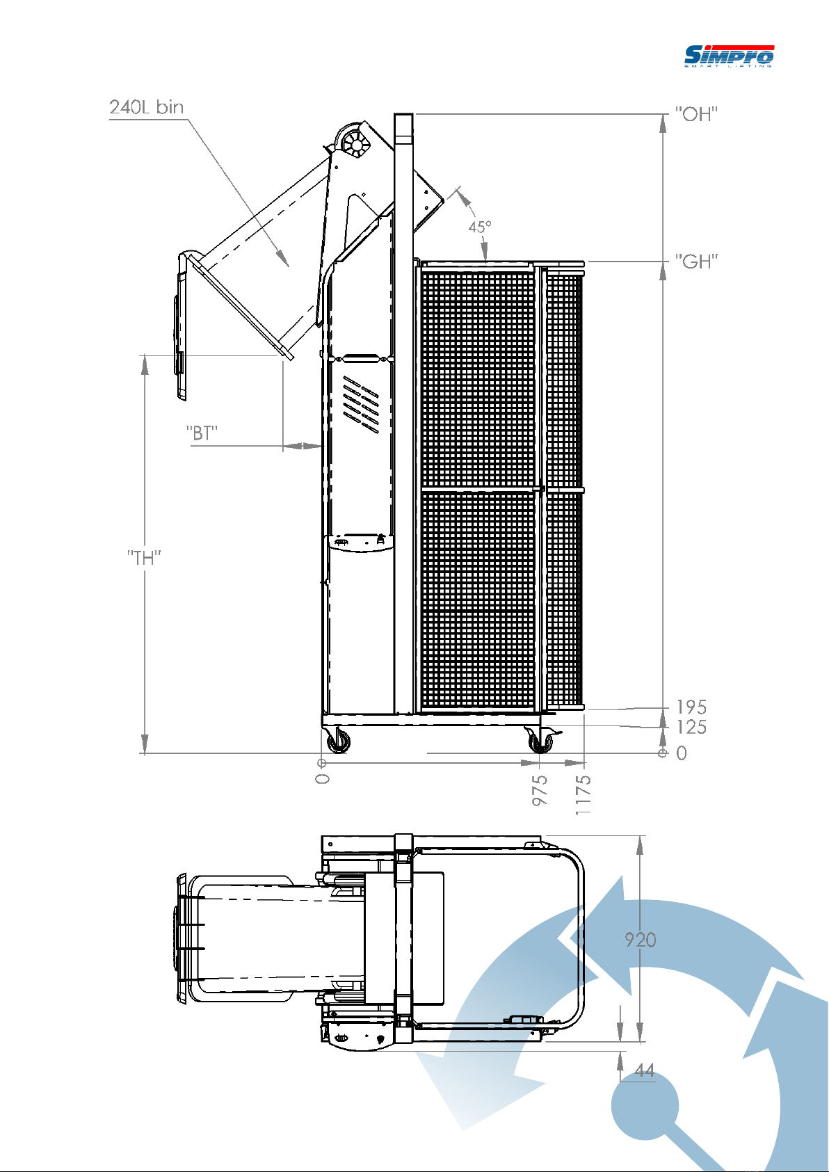
1. A unique tipping action
whereby bins are lifted
straight up, and then gently
rolled forward around the lip
of the skip or hopper being
emptied into. Benefits of this
design include a small
‘footprint’, and a wide range
of tipping heights available, from
700mm to more than six metres.
2. A standard weight capacity of 250kg.
3. A very reliable, maintenance-free design.
4. A fully hot-dip galvanised frame and cradle
as standard (with options for full or partial
stainless steel for hygiene-critical areas).
5. A standard cradle which lifts almost all
EN840 wheelie bins without clamping or
retaining.
6. A modular design which can be easily modified to suit a wide range of non-standard
bin sizes, shapes, and weights.
2.2 Construction
The Dumpmaster consists of a steel frame with vertical masts and stabilizing legs, bin cradle,
hydraulic ram, hydraulic powerpack, powerpack cover, control panel, electronic control
systems, guarding, castor wheels, and power lead or charging cable.

User Manual | Simpro Dumpmaster®
Original Instructions | English | v59.0 | December 2019 | Page 6
2.3 Mechanism
When the RAISE button is pressed, a hydraulic ram is extended, which pulls on an
arrangement of chains, causing the bin cradle to travel vertically in the masts. The cradle is
inverted at the appropriate height by an arrangement of arms, rollers, and a curved track.
The ram is supplied by a hydraulic power pack, which may have a 3-phase, 1-phase, battery,
or compressed-air motor. Electrical, hydraulic, and / or mechanical control mechanisms
allow the operator to raise or lower the bin in a controlled manner.
2.4 Safe Lifting Capacity
The Safe Lifting Capacity of the standard model Dumpmaster is 250 kilograms (550lb).
Some machines may be specified with different capacities to suit custom requirements. Refer
to the machine’s rating plate to verify the factory-designated Safe Lifting Capacity on any
given machine.
Safe Lifting Capacity is a gross figure, referring to the weight of the bin, its contents, and
any other external objects which have been placed on the cradle.
Never attempt to lift more than the factory-designated Safe Lifting Capacity noted on
the rating plate.
2.5 Duty cycle
The duty cycle of the Dumpmaster depends on the type of power supply and powerpack
that is fitted to the machine, as well as various environmental factors and the manner in
which the machine is used. The figures given below are estimates only.
Power Supply
Throughput (net
tipped material)
No. of bins equivalent
(average ~100kg each)
Measurement Unit
Battery
10,000kg
100 bins
per charge
Battery + Continuous
Charge
2,000kg
20 bins
per hour, nonstop
Battery + Solar Panel
3,000kg
30 bins
per day (in mostly
sunny conditions)
1-Phase Mains
6,000kg
60 bins
per hour, nonstop
3-Phase Mains
12,000kg
120 bins
per hour, nonstop
The standard Dumpmaster uses a battery power supply. Check the rating plate of your
machine if you are unsure of what type of power it uses.

2.6 Intended operational life
The intended operational life of the Dumpmaster is as follows:
Average Gross Bin Weight
Intended Operational Life
< 100kg
200,000 cycles
100kg –200kg
150,000 cycles
200kg –250kg
100,000 cycles
250kg –300kg
75,000 cycles
> 300kg
50,000 cycles
2.7 Noise emissions
The noise emissions of the Dumpmaster bin lifter in standard operation have been assessed
as not exceeding ~60 dB(A) at the operator’s ear.
Operators are not required to wear hearing protection but are recommended to do so if
using the machine on a constant basis.
ISO standards for machinery safety specify that noise emissions are to be measured in A-
weighted decibels (dB(A)), a unit of volume which is adjusted to reflect the sensitivity of
human hearing. The measurements are taken at a point 1.6 metres above the ground at
the operator’s working position.
2.8 Environmental restrictions
The Dumpmaster may be used indoors or outdoors. However the following restrictions apply:
1. Minimum floor area 2 square metres, with a clear passage to exits;
2. Height above sea level not more than 1000m;
3. Ambient temperature not higher than +40℃and not lower than -10℃;
4. At ambient temperatures above 35℃, the relative humidity should not exceed 50%; at
lower temperatures, higher relative humidity is permitted;
Never operate the machine in flammable, explosive, corrosive, acidic or alkaline
environments.
2.9 Ingress protection
Item
IP Rating
Push buttons, switches and lamps
IP66
Door interlock
IP66
Coded magnetic switch
IP66
Motor
IP54 (note additional protection provided by covers)
Overall
IP56 (optional upgrade to IP66 or IP69K)

User Manual | Simpro Dumpmaster®
Original Instructions | English | v59.0 | December 2019 | Page 8
2.10 Notes
1. This User Manual describes approved procedures for the operation, maintenance,
and routine inspection of the Dumpmaster hydraulic bin-tipping machine.
2. This manual is written in English, and is to be considered the ‘Original Instructions’ for
the purposes of EU Machinery Directive 2006/42/EC.
3. Operator(s) must read and understand this manual before using the machine.
4. If the machine is to be leased, sold or otherwise transferred, then this manual shall
accompany the machine.
5. This is a generic manual. Simpro reserves the right to change the design of our
products at any time without notification. In cases where the manual does not
correspond with the actual product, use the manual as a reference guide only, and
contact your authorized Simpro agent for assistance if required.
6. Contact your authorized Simpro agent if you encounter any problems or faults with
the machine.
7. Errors in this manual should be reported by email to info@simpro.world.

3.Safety Assessment
The Dumpmaster has been designed to be as safe as possible without restricting the ease-of-
use and versatility of the machine.
A Hazard and Risk Assessment should be undertaken before the Dumpmaster is used for
the first time, as described in Section 3.4.
3.1 Safety features
The safety features of the standard Dumpmaster design are as follows:
1. Welded mesh and sheet-metal panels prevent personnel access to all moving parts.
2. A safety interlock system which disables the machine unless the door is shut, and
electrically locks the door as soon as the cradle leaves the ground.
3. A tipping action which maintains the weight of the bin within the machine footprint.
4. A pressure-compensating lowering valve which automatically regulates the lowering
speed regardless of the weight of the bin.
5. A control system which either:
a. stops the machine unless continuous operator input is received, or;
b. features a prominent EMERGENCY STOP button to disable the machine.
3.2 Reasonably foreseeable misuse
The reasonably foreseeable misuse considered in the standard Dumpmaster design is as
follows:
1. Attempts to use the machine by untrained operators;
2. Attempts to empty bins that the cradle is not specifically designed to hold;
3. Attempts to bypass the door interlock or other safety systems;
4. Attempts to clear spilt material from inside the guarding without proper procedures;
5. Attempts to clean the machine without following proper procedures.
3.3 OSH Compliance Specification Guide
Companies in most jurisdictions (including Australia, NZ, UK, USA, Canada and the EU) are
required by law to provide a safe workplace for their staff, including ensuring that all new
and existing machinery is safe to operate.
Although the particulars of safety legislation differ, most countries accept that machinery is
‘safe to operate’ if it can be demonstrated to comply with ISO 13849-1:2015 (or a regional
equivalent thereof).
ISO 13849-1:2015 may call for additional guarding and safety features, depending on the
particular circumstances in which a machine is to be used. The purpose of this section is to
assist potential Dumpmaster owners to determine whether special safety features may be
required on their machine.

User Manual | Simpro Dumpmaster®
Original Instructions | English | v59.0 | December 2019 | Page 10
ISO 13849-1:2015 is a machinery-safety standard issued by the International Standards
Organisation. It provides safety requirements and guidance on the principles for the
design and integration of safety-related parts of control systems (SRP/CS), including the
design of software.
ISO 13849-1 has been modified for local conditions and reissued under different
terminology by some national standards authorities. In Australia and New Zealand the
equivalent (almost identical) standard is called AS/NZS 4024.1:2014.
In the USA, ANSI standards are commonly used to demonstrate the safety of machinery,
rather than ISO 13849-1. However since the US model relies largely on ‘best practise’ and
‘liability’ to enforce workplace H&S norms, US companies who demonstrate machinery
safety using ISO 13849-1 may be considered to have met or exceeded their H&S
obligations.
3.3.1 The ISO 13849-1:2015 safety model
Unlike the ‘system architecture’ model used by earlier safety standards, ISO 13849-1:2015 uses
a ‘functional safety’ model of machinery safety. That is, it takes account of the reliability of
parts as well as other factors to create a comprehensive measure of the risk reduction
achieved by a safety function –an indicator called Performance Level (PL).
The standard defines five Performance Levels, ranging from PL(a) (lowest performance) to
PL(e) (highest performance).
The standard also defines the Performance Level that a given safety function must achieve
to reduce the risk to an acceptable level –a value called Performance Level required (PLr).
3.3.1.1 Determining the Performance Level required (PLr)
As defined by the ISO 13849-1:2015 safety model, the minimum acceptable PLr for any given
safety function is based on three input parameters:
1. Severity of injury expected from the associated hazard
2. Frequency and/or duration of exposure to the associated hazard
3. Possibility of manually avoiding the associated hazard
The following table may be used to determine the acceptable PLr from these parameters.
Safety Function PLr Determination Table
Severity of injury
expected from
hazard
Frequency and/or duration
of exposure to hazard
Possibility of manually
avoiding the hazard
Minimum
acceptable PLr
Slight injury
(reversible)
Seldom to quite often and/or
exposure time is short
Possible under specific
conditions
PL(a)
Scarcely possible
PL(b)
Frequent to continuous
and/or long exposure time
Possible under specific
conditions
Scarcely possible
PL(c)
Serious injury or
death
(irreversible)
Seldom to quite often and/or
exposure time is short
Possible under specific
conditions
Scarcely possible
PL(d)
Frequent to continuous
and/or long exposure time
Possible under specific
conditions
Scarcely possible
PL(e)

To demonstrate compliance with ISO 13849-1:2015, the minimum acceptable PLr of the
safety functions must be assessed for each identified hazard in the specific conditions in
which the machine is to be used.
The safety function PLr may be assessed as part of the regular Hazard and Risk
Assessment described in Section 3.4. Although this assessment includes all hazards intrinsic
to the Dumpmaster design, other safety functions may be necessary to address hazards
specific to your intended conditions of use. These can be assessed in the blank spaces
provided.
3.3.1.2 Achieving the Performance Level required (PLr)
As standard, all hazards intrinsic to the Dumpmaster design are addressed by safety functions
with a minimum performance of PL(c).
Therefore, additional or customised safety systems are only required in the following cases:
1. The customer’s assessment identifies that hazards exist which have been addressed in
the standard Dumpmaster design, but which, due to conditions specific to their
intended conditions of use, require safety function performance of PL(d) or PL(e).
2. The customer’s assessment identifies that hazards exist which are entirely specific to
their intended conditions of use, and which have therefore not been addressed in
the standard Dumpmaster design.
3. The customer is subject to corporate policies, union contracts, OSH regulations or
other external factors which demand safety function performance of PL(d) or PL(e),
irrespective of the ISO 13849-1:2015 safety model.
In any of these cases, information about the required safety function PLr should be provided
to Simpro before placing an order. Simpro will then propose additional or uprated systems to
achieve the PLr in compliance with ISO 13849-1:2015. This may include any or all of the
following:
-Upgrade of control system architecture to Category 3 or Category 4
-Additional guarding panels
-Remote control systems
-Training of personnel
-Signage and floor markings
3.4 Hazard and Risk Assessment Guide
Most jurisdictions require machinery owners to conduct a Hazard and Risk Assessment for
their equipment, which considers all relevant factors such as the area it is used, the skill and
training of operators, the proximity of other persons, frequency of use, etc.
The following section is not a complete site-specific Hazard and Risk Assessment, but an
assessment of the risk factors that are intrinsic to the Dumpmaster design. Blank template
spaces are provided for additional site-specific hazards.
The procedure for carrying out a Hazard and Risk Assessment is typically defined with
reference to ISO 12100:2010, issued by the International Standards Organisation. This

User Manual | Simpro Dumpmaster®
Original Instructions | English | v59.0 | December 2019 | Page 12
standard describes procedures for identifying hazards and estimating and evaluating risks
during relevant phases of a machine life cycle.
As with all powered industrial equipment, some hazards will remain despite any
precautions undertaken by the manufacturer or owner of the machine. It is essential that
operators are aware of these residual hazards and what they must do to prevent harm to
themselves or to others, as described in Section 3.4.3.
3.4.1 ISO 12100:2010 risk assessment model
In the ISO 12100:2010 risk assessment model, each identified hazard is given a Risk Factor,
from which is derived a final Risk Evaluation. These parameters can be determined as follows.
3.4.1.1 Determining Risk Factor
The Risk Factor associated with any given hazard may be calculated using the following
table, with the formula: Risk Factor = LO x FE x DPH x NP
3.4.1.2 Determining Risk Evaluation
Once the Risk Factor has been calculated, the Risk Evaluation of the hazard can be
determined from the following table:
LO
Likelihood of
Occurrence
FE
Frequency
of Exposure
DPH
Degree of
Possible Harm
NP
Number of
Persons at risk
0.1
Impossible, or
possible only in
extreme
circumstances
0.1
Infrequently
0.1
Scratch or
bruise
1
1 –2 persons
0.5
Highly unlikely
though
conceivable
0.2
Annually
0.5
Laceration,
mild ill-health
2
3 –7 persons
1
Unlikely but
could occur
1
Monthly
1
Break minor
bone or illness
(temporary)
4
8 –15 persons
2
Possible but
unusual
1.5
Weekly
2
Break major
bone or illness
(permanent)
8
16 –50
persons
5
Even chance –
could happen
2.5
Daily
4
Loss of 1 limb
or eye/serious
illness
(temporary)
12
51 or more
persons
8
Probable –not
surprised
4
Hourly
8
Loss of 2 limbs
or eyes/serious
illness
(permanent)
-
-
10
Likely, only to be
expected
5
Constantly
15
Fatality
-
-
15
Certain, no
doubt
-
-
-
-
-
-
Risk Factor
0-1
2-5
6-10
11-50
51-
100
101-500
501-1000
1001 +
Risk
Evaluation
Negli-
gible
Very
Low
Low
Significant
High
Very
high
Extreme
Unacce-
ptable

3.4.2 Identified Hazards
The following hazards have been identified that are intrinsic to the Dumpmaster design. For
each hazard a full Risk Evaluation has been completed and control measures described.
Blank template spaces are provided at the end for machinery owners to identify, assess
and control additional site-specific hazards.
Entanglement or amputation of fingers or limbs in moving parts
Operator
LO:
0.5
FE:
4
DPH:
1
NP:
1
Risk
Factor:
2
Guarding prevents access to all moving parts and trapping hazards.
Other
persons
LO:
1
FE:
4
DPH:
1
NP:
1
Risk
Factor:
4
As above.
Control
measures
Operators are responsible to obey warning signs fitted to the machine and
instructions, regarding keeping himself and others clear of all moving parts.
Comments
The Dumpmaster is designed so that trapping hazards are eliminated,
minimized or isolated.
Crushing by unauthorized rapid descent of cradle
Operator
LO:
0.5
FE:
4
DPH:
1
NP:
1
Risk
Factor:
2
The operator is protected from the cradle by the frame and guarding during
operation. A door safety interlock ensures that the door can only be opened
when the cradle is on the ground, and the cradle cannot be raised unless
the door is closed and locked.
Significant safety margins ensure that the probability of failure of any steel,
hydraulic, or control parts failing is very low.
Other
persons
LO:
0.5
FE:
4
DPH:
1
NP:
1
Risk
Factor:
2
As above.
Control
measures
Operators are responsible to obey warning signs fitted to the machine and
instructions, regarding keeping himself and others away from the area under
the cradle when raised.
The machine must be regularly maintained, and all faults repaired
immediately.
Comments
A hydraulic speed-control valve limits the maximum speed of descent in
normal use.
Operator or others being hit by falling or flying debris
Operator
LO:
1
FE:
4
DPH:
0.5
NP:
1
Risk
Factor:
2
The operator is protected from the cradle by the frame and guarding during
operation. There is some risk if items such as broken glass are being tipped.
Other
persons
LO:
1
FE:
4
DPH:
0.5
NP:
1
Risk
Factor:
2
There is some risk to others standing close to the bin if items such as broken
glass are being tipped
Control
measures
Operators are responsible to obey all instructions and warning signs
regarding keeping himself and others away from the machine while in use.
If tipping items such as glass, metal or liquids, glasses and gloves should be
worn
Comments

User Manual | Simpro Dumpmaster®
Original Instructions | English | v59.0 | December 2019 | Page 14
Crushing if the machine falls over
Operator
LO:
0.5
FE:
2.5
DPH:
1
NP:
1
Risk
Factor:
1.25
Low risk as Dumpmaster tippers are very stable and the bin centre of gravity
remains well within the machine’s footprint throughout the tipping cycle.
Other
persons
LO:
0.5
FE:
2.5
DPH:
1
NP:
1
Risk
Factor:
1.25
As above.
Control
measures
Do not operate on soft ground, or ground with a slope of more than 1:12.
Never attempt to empty liquids from closed-top drums.
Comments
Electrocution or electric shock
Operator
LO:
1
FE:
4
DPH:
15
NP:
1
Risk
Factor:
60
Some risk is always present with mains leads.
Other
persons
LO:
1
FE:
4
DPH:
15
NP:
1
Risk
Factor:
60
As above.
Control
measures
Fit a Residual Current Device (RCD) to all power sockets.
Check all leads frequently and repair or replace if damaged.
All leads should be checked and tagged by a registered electrician at
regular intervals.
Comments
Mains-powered Dumpmasters are earthed and comply with AS60204.1.
The charger on battery-powered Dumpmasters is double-insulated.
Contamination from tipping toxic powder and liquid
Operator
LO:
2
FE:
4
DPH:
1
NP:
1
Risk
Factor:
8
Great care should be taken when tipping powder or liquids.
If the product could cause any harm whatsoever to the operator or to any
other person, ensure all persons are well protected.
An operator screen may be fitted.
Other
persons
LO:
2
FE:
4
DPH:
1
NP:
1
Risk
Factor:
8
As above.
Control
measures
The operator must wear appropriate protective equipment, and ensure that
all other persons are well clear of the area.
Powder should only be tipped when there is no wind, and/or a wind shield
should be installed.
Comments
Substances of a toxicity that cannot be protected against with PPE should
not be emptied with a Dumpmaster. Alternative methods should be used.
Damage to skin when used in extreme weather conditions
Operator
LO:
2
FE:
4
DPH:
1
NP:
1
Risk
Factor:
8
If the machine is to be used in extreme cold or heat, the operator must wear
gloves and other suitable Personal Protective Equipment.
Other
persons
LO:
2
FE:
4
DPH:
1
NP:
1
Risk
Factor:
8
As above.
Control
measures
Operators must wear appropriate Personal Protective Equipment (PPE) when
operating machinery in extreme weather conditions.
Comments
See Section 2.8 for Dumpmaster environmental restrictions.

Site-specific hazard:
Operator
LO:
FE:
DPH:
NP:
Risk
Factor:
Other
persons
LO:
FE:
DPH:
NP:
Risk
Factor:
Control
measures
Comments
Site-specific hazard:
Operator
LO:
FE:
DPH:
NP:
Risk
Factor:
Other
persons
LO:
FE:
DPH:
NP:
Risk
Factor:
Control
measures
Comments
Site-specific hazard:
Operator
LO:
FE:
DPH:
NP:
Risk
Factor:
Other
persons
LO:
FE:
DPH:
NP:
Risk
Factor:
Control
measures
Comments
Site-specific hazard:
Operator
LO:
FE:
DPH:
NP:
Risk
Factor:
Other
persons
LO:
FE:
DPH:
NP:
Risk
Factor:
Control
measures
Comments
User Manual | Simpro Dumpmaster®
Original Instructions | English | v59.0 | December 2019 | Page 16
Site-specific hazard:
Operator
LO:
FE:
DPH:
NP:
Risk
Factor:
Other
persons
LO:
FE:
DPH:
NP:
Risk
Factor:
Control
measures
Comments
Site-specific hazard:
Operator
LO:
FE:
DPH:
NP:
Risk
Factor:
Other
persons
LO:
FE:
DPH:
NP:
Risk
Factor:
Control
measures
Comments
3.4.3 Residual Hazards
As with all powered industrial equipment, some ‘residual hazards’ may be present despite
any guarding or safety measures implemented by the manufacturer.
The machinery owner has a legal responsibility to identify and assess these residual hazards,
and to take all reasonable precautions to eliminate, isolate, or minimize them. Such
precautions may include any or all of the following:
Taking steps to monitor and enforce the training of operators.
Design and implementation of Standard Operating Procedures.
Using disciplinary measures to ensure the Standard Operating Procedures are followed.
Posting signage, floor marking, or other warnings as deemed appropriate.
Taking steps to develop a culture of safety and open communication among staff.

3.5 Safety Norms
The following safety norms must be observed for the safe use of a Dumpmaster bin lifter.
Only trained and authorised personnel are permitted
to use the machine.
Operators must read and obey the instructions
displayed on the machine.
Never operate the machine on soft ground, or
ground with a slope ratio greater than 1:12.
Never operate machine on the edge of a raised dock
or platform, unless designed for that application.
Never operate the machine with any covers or
guards removed.
Never attempt to empty the contents of closed-top
drums, unless the machine is securely bolted down.
All persons other than the operator must keep at
least two metres clear while the machine is in use.
Always keep hands and feet well clear of the bin and
cradle when operating.
Do not place limbs, feet or foreign objects under the
side guards or safety door.
Do not attempt to empty over-filled or overflowing
bins.

User Manual | Simpro Dumpmaster®
Original Instructions | English | v59.0 | December 2019 | Page 18
Before connecting machine to mains supply,
ensure voltage and frequency correspond with
that listed on the rating plate.
Do not use an extension lead longer than 15
metres to connect the machine to mains power.
Do not operate if power lead, insulation or power
plugs are damaged.
Do not connect a damp power plug or socket.
Ensure the power supply socket is fitted with a
residual current device.
Ensure there is complete continuity between the
machine and an effective earthing system which
complies with local and national regulations. The
manufacturer cannot be held liable for the
consequences of an inadequate earthing system.
4. Operat ing Instructions
4.1 Before operation
Before operating a Dumpmaster of any type, check the following points to ensure that the
machine is stable and safe to use.
1. The machine is on level hard ground, with a slope of 1:12 or less.
2. All covers and safety guards are in place.
3. The wheel brakes are applied, and/or the feet are wound down onto the ground.
4. All personnel other than the operator are well clear of the machine.
5. The cradle is fully lowered.
6. The key is inserted and turned to the ON position.
7. The battery indicator (if fitted) shows an acceptable level of charge.
4.2 Emplacing and removing bins
All personnel using the machine must know how to correctly emplace and remove bins
from the machine. Bins that are not correctly emplaced may come loose and damage
the machine while being lifted, or fall out when inverted.
The bin cradle is designed to allow bins to be emplaced and removed easily, while also
holding them securely throughout the lifting and tipping cycle. A range of different cradles
may be installed, depending on the types of bin that the machine needs to empty. Use the
following table to identify the correct instructions for your machine.
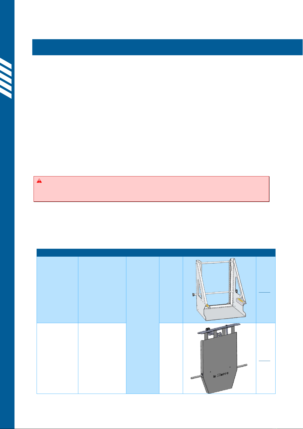
4.2.1 Cradle identification
Cradle Type
Primary Usage
Bin Compatibility
Cradle Image
Refer
EN840 Base-lift
Cradle
(standard)
Waste
management
applications in
all regions
except North
America
EN840-
compliant
Wheelie
Bins
-60L
-80L
-120L
-140L
-240L
4.2.2
EN840 Comb-
lift Cradle
Waste
management
applications in
UK and Europe
-60L
-80L
-120L
-140L
-240L
-360L
4.2.3
Other manuals for Dumpmaster
1
Table of contents
Other Simpro Industrial Equipment manuals


Popular Industrial Equipment manuals by other brands


HBK
HBK PW27BP Mounting instructions

3M
3M 3M-Matic 300cf Instructions and parts list

MULTIQUIP
MULTIQUIP GLOBUG Series Operation and parts manual

JB INDUSTRIES
JB INDUSTRIES REVOLVER 26233 quick start guide

Versum Materials
Versum Materials GASGUARD AP10 Installation, operation & maintenance manual

Weaver Leather
Weaver Leather FOIL & HOT quick start guide


