EFA EFA VB 315 User manual
OM NO.: 001 580 603
Stand / Version
04 / 2017
Originalbetriebsanleitung
Translation of the original Operating manual
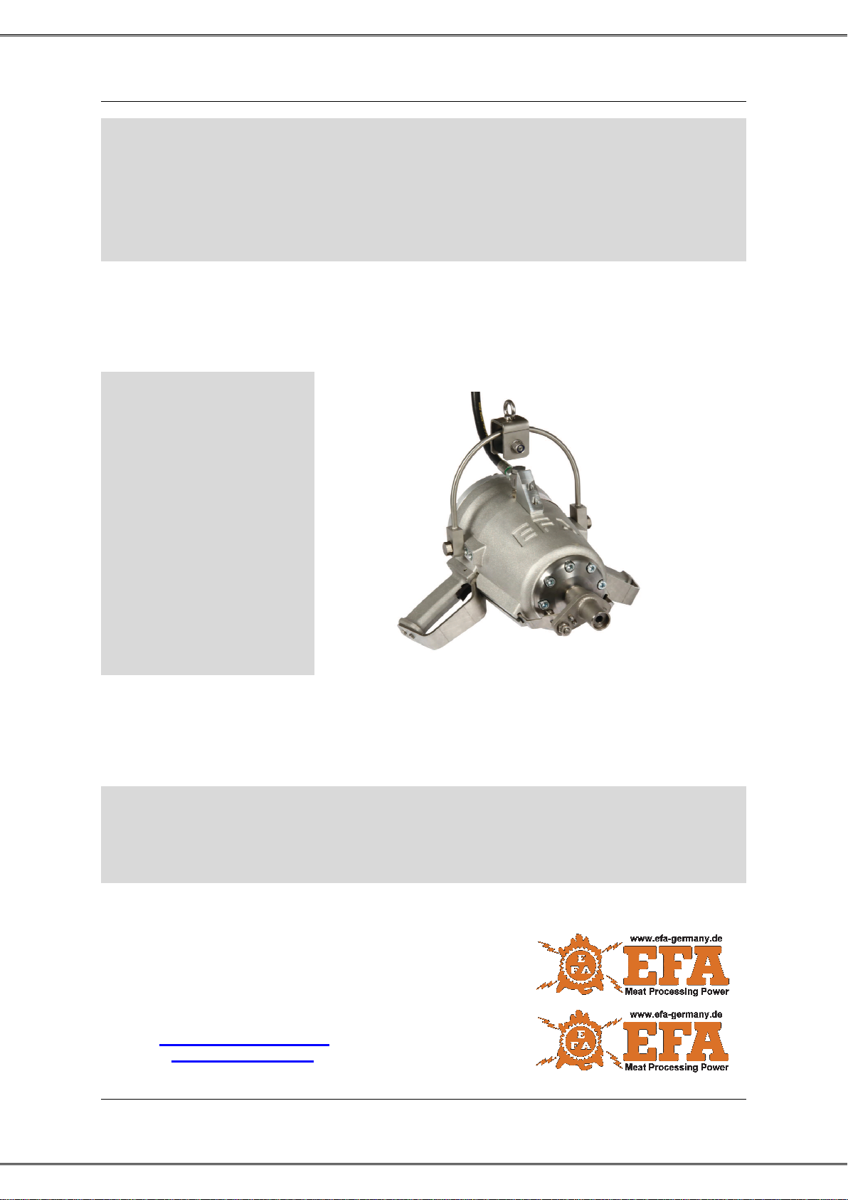
Stunning device
Stunning Device
EFA VB 315
Wichtige Informationen: Diese Anleitung unbedingt dem Bedienpersonal aushändigen!
Important Information: Please forward these operating instructions to your operating personnel!
Schmid & Wezel GmbH
Maschinenfabrik
Maybachstraße 2
75433 Maulbronn, Germany
Phone: +49(0)7043 / 102-0
Fax: +49(0)7043 / 102-78
E-mail: verkauf@efa-germany.de
Website: www.efa-germany.de

Schmid & Wezel
Seite / Page
2 of 13
Stand / Version
04 / 2017
Table of contents
1Use, scope of supply, accessories................................................................... 3
1.1 Symbols used in this manual................................................................................................... 3
1.2 Intended use............................................................................................................................ 3
1.2.1 Application area........................................................................................................ 3
1.2.2 Residual risks ........................................................................................................... 3
1.3 Delivery content....................................................................................................................... 3
2Safety instructions............................................................................................. 4
2.1 General safety instructions...................................................................................................... 4
2.2 Conduct at the workplace........................................................................................................ 4
3Connection and start-up.................................................................................... 4
3.1 Initial Operation........................................................................................................................ 4
3.1.1 Spring balancer......................................................................................................... 4
3.1.2 Compressor.............................................................................................................. 5
3.1.3 Connecting the stunning device ............................................................................... 5
3.1.4 Uncoupling the stunning device................................................................................ 5
3.2 Working with the stunning device............................................................................................ 5
3.2.1 Operation.................................................................................................................. 6
3.2.2 Operating safety ....................................................................................................... 6
4Assembly............................................................................................................ 6
4.1 Replacing parts........................................................................................................................ 6
4.2 Adjustment of the spring balancer........................................................................................... 7
5Maintenance ....................................................................................................... 7
6Repair and troubleshooting .............................................................................. 8
7Cleaning and maintenance...............................................................................10
7.1 Disinfection and cleaning during operation ........................................................................... 10
7.2 Daily cleaning after completion of the slaughter.................................................................... 10
7.2.1 Cleaning the stunning device ................................................................................. 10
7.3 Maintenance.......................................................................................................................... 10
7.3.1 Before and during slaughtering: ............................................................................. 10
7.4 After slaughtering................................................................................................................... 11
7.5 Wear...................................................................................................................................... 11
7.6 Maintenance unit ................................................................................................................... 11
Repairs........................................................................................................................................... 11
8Transport and storage......................................................................................11
9Return of waste electrical equipment..............................................................11
Appendix
A1 Technische Daten / Technical Data .................................................................12
A2 Maßblatt / Dimension sheet..............................................................................12
BInstallationsplan / Installation Plan..................................................................13

Schmid & Wezel
Seite / Page
3 of 13
Stand / Version
04 / 2017
1 Use, scope of supply,
accessories
Information that must be read!
This manual is intended for the machine opera-
tor. Keep it in a safe place!
The stunning device is operated with com-
pressed air.
The stunning device may only be used:
In technically sound condition, for the
intended use and in awareness of
safety and dangers.
With all the safety devices attached.
In compliance with the safety instruc-
tions.
After operating personnel have read
and understood these instructions, par-
ticularly Chapter 2 “Safety instructions”
and Chapter 3 “Connection and start-
up”. Only in this way can incorrect oper-
ation be avoided and hazard situations
correctly assessed.
Never aim the device at peo-
ple!
Never reach into the area of
the piston, otherwise you
could injure yourself.
Wear ear protectors during
work!
1.1 Symbols used in this man-
ual
Hazard symbol:
Non-compliance results in an imminent risk of
injury for the operating personnel and/or third
parties. In addition the machine may get dam-
aged.
This symbol is used for situa-
tions where extreme caution is
advised.
Information symbol:
Texts marked with this
symbol contain im-
portant information and
useful tips.
1.2 Intended use
1.2.1 Application area
The stunning device EFA VB 315 is
adapted for stunning calves, cattles,
cows and bulls with 121mm depth of im-
pact.
The machine is not equipped for a different type
of use. If the operator wishes to use the device
for other purposes, please consult Schmid &
Wezel GmbH.
For all other applications, the risk of injury
and/or increased wear must be noted. In the
event of non-compliance, the liability shall be
borne by the user alone.
1.2.2 Residual risks
Since the stunning device is intended for indus-
trial use on animal carcasses, there is a risk of
injuring yourself and, in the case of extreme
misuse, of fatally injuring others. Misuse may
result in immediate death or death from bleed-
ing. Therefore, please make sure that you han-
dle the machine correctly.
1.3 Delivery content
Stunning device EFA VB 315
Operating manual

Schmid & Wezel
Seite / Page
4 of 13
Stand / Version
04 / 2017
2 Safety instructions
2.1 General safety instructions
Be sure to observe the following safety precau-
tions when working with the stunning device.
It is assumed that all work involving op-
eration of the stunning device is always
completed by adequately skilled operat-
ing personnel.
Select your personal protective equip-
ment according to the regulations appli-
cable on the premises.
Installation, maintenance and repair
work may only be carried out by author-
ised and qualified personnel.
Stunning devices from Schmid & Wezel
comply with the relevant safety regula-
tions.
2.2 Conduct at the workplace
Keep your workplace tidy and in good
working condition. Untidiness can lead
to accidents.
Take into account environmental influ-
ences. Ensure good lighting (min. 500
lux).
Keep other persons away from your
workplace. Remain focused and act
with caution during your work. Do not
use the stunning device when you are
unconcentrated and/or tired.
Keep the stunning device in a safe
place. Store unused equipment in a dry
place.
Work clothing: Do not wear loose cloth-
ing or jewellery as these could become
tangled up in moving parts. Wear sturdy
shoes during your work.
Avoid abnormal body postures. Ensure
safe footing and keep your balance at
all times.
Service your tools with care.
Only use EFA original accessories. Use
of other tools or accessories may result
in injury to yourself.
Use of non-original accessories will
void the warranty.
Modifications and alterations to the ma-
chine are not permitted and exempt
S&W from any warranty and liability.
3 Connection and start-
up
Checking the impact energy of the stun-
ning device
Testing is only possible with the tester MEVB
100 - (008011633 and corresponding attach-
ment 003013881). The test cycle must be de-
termined according to the operating standards.
Place of work
The operator requires a working space of at
least 1.5 sq. m. No other place of work should
extend into this area, as the movements with
the stunning device could result in the risk of in-
jury.
The illumination at the place of work must be at
least 500 lux.
3.1 Initial Operation
Switch off the stunning device
before connecting to the com-
pressor!
Important information, e.g.
technical data sheets, draw-
ings and parts lists can be
found in Appendix A.
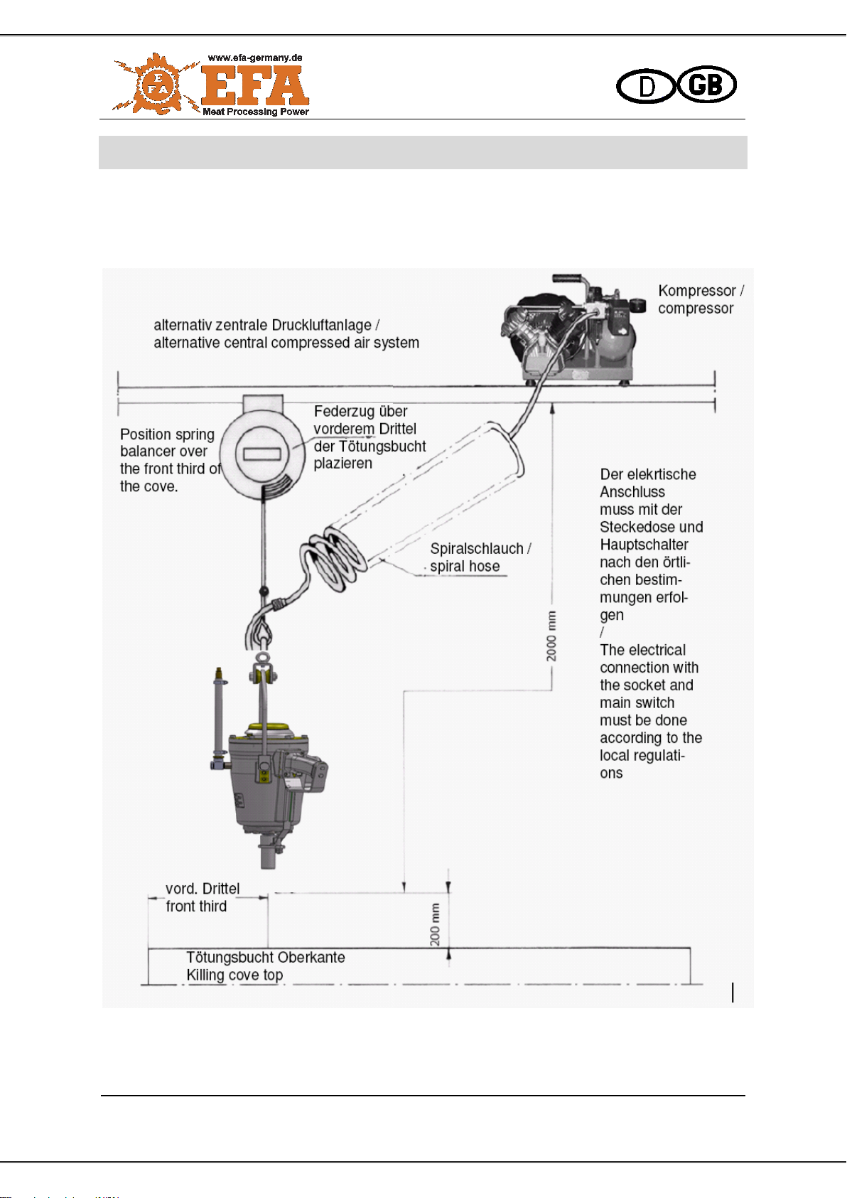
3.1.1 Spring balancer
Operate the stunning device always in combi-
nation with a weight relief (spring balancer).
Thereby, the stunning device should be posi-
tioned over the killing cove at the spring bal-
ancer. Use a sliding trolley to attach the spring
balancer to a higher element above the work-
place or to the ceiling. Information on fine ad-
justment of the spring balancer is provided in
Chapter 4.2 “Adjustment of the spring bal-
ancer”.
Suspend the stunning device so that it is as top-
heavy as possible. The vertical position can be
adjusted if necessary.

Schmid & Wezel
Seite / Page
5 of 13
Stand / Version
04 / 2017
Due to the weight of ap-
prox. 19 kg, there is a risk
of injury through the unit
slipping or falling down
when fixing or loosening
the weight relief system.
Pay attention that the de-
vice does not catch on
the snap hooks or the
hook of the stunning de-
vice. Work cautiously!
Set aside an unused stunning device in such a
way that unintentional contact is impossible.
3.1.2 Compressor
A compressor is intended for the operation of
the stunning device
3.1.3 Connecting the stunning device
Installation work may only be
carried out by authorized
specialist personnel.
Switch off the device before
connecting to the com-
pressed air supply!
Procedure (see installation of the device in
Appendix A “Installationsplan / Installation
plan”
To ensure that the required
operating pressure is availa-
ble at the workplace, a
maintenance unit must be
permanently installed.
Before connecting:
Before connecting the stunning device,
check that the trigger and the safety
bushing are smooth-running (see Fig.
1Safety bushing).
Check if the operating pressure is pre-
sent.
For coupling, pull back the knurled
shaft of the quick connect, lock in the
quick coupling to the hose plug and re-
lease teh knurled shaft.
Fig. 1 Safety bushing and trigger
The device is not secured
against exceeding the max.
operating pressure of 14 bar.
3.1.4 Uncoupling the stunning device
When uncoupling, the com-
pressed air system must be
depressurized.
Pull back the knurled shaft of the quick
coupling and hold against the stop.
After venting the pressurised chambers
of the device, bring the knurled shaft to
its initial position and pull off spiral pres-
sure hose.
3.2 Working with the stunning
device
Do not use the stunning de-
vice until you have read this
manual and made the correct
connection!
Never reach into the area of
the piston if the stunning de-
vice is connected!
Never aim the stunning device
at people!

Schmid & Wezel
Seite / Page
6 of 13
Stand / Version
04 / 2017
Wear ear protectors during
work!
3.2.1 Operation
Preparation
Before use, check that the operating data of
compressed air supply and device match.
Before starting work, also check whether
the operating pressure of 14 bar is set
for cows, bulls and calves as suggested
by EFA.
the stunning device is functioning
the device is tight
the general safety instructions in Chap-
ter 2.1 “General safety instructions”
(Page 5) have been followed
Fig. 2 Stun points
For stunning, place the device
on the animal's head as shown
in Fig. 2.
The device must be guided on both handles.
The operator's head must be at
the side of the stunning device
to prevent injury when it re-
coils!
Operate the trigger on the handles and
place the stunning device on the ani-
mal's head.
The safety bushing triggers the shot.
Lift the stunning device immediately
from the animal's head after the shot
has been fired.
Let go of the trigger on the handles at
the same time.
The stunning device is then ready for
operation again.
After letting go of the triggers, the piston moves
back to its initial position.
3.2.2 Operating safety
Stunning device
Act with particular caution when con-
nected.
Never operate the trigger when the
stunning device is not in operation.
Lift the stunning device immediately
from the animal's head after the shot
has been fired.
For safer handling (guidance), the stun-
ning device must be suspended from a
spring balancer.
4 Assembly
Disconnect the stunning device
from the air pressure net before
any assembly!
4.1 Replacing parts
Only use EFA original accesso-
ries. Use of other tools or ac-
cessories may result in injury
to yourself. Use of non-original
accessories will void the war-
ranty.
Only authorized specialist per-
sonnel may replace parts.
Replace parts only when the
device is disconnected from
compressed air.
Work only with a fully function-
ing device; otherwise, there is
a risk of accident.

Schmid & Wezel
Seite / Page
7 of 13
Stand / Version
04 / 2017
Caution: Non-observance of the stipulated
tightening torque can lead to breaking of the
thread inserts in the housing.
4.2 Adjustment of the spring
balancer
The spring balancer setting is fine-tuned by
means of the PLUS/MINUS screw on its hous-
ing (see Fig. 3).
Fig. 3 Spring balancer
Turn the screw in MINUS direction until
the device is in free-floating in balance
(with the tension spring) at working
height.
If pulling out is not possible, the spring balancer
is jammed, and a readjustment is necessary:
Turn the screw in PLUS direction until
the saw can be pulled out and start the
fine adjustment again (see above).
5 Maintenance
Malfunctions may occur during operation, but
these are generally relatively simple to remedy.
Table 1: “Malfunctions and their remedy” lists
these malfunctions with possible causes and
possible remedies.
To remedy malfunctions, be
sure to disconnect the unit
from the compressed air hose
Have all work carried out only
by qualified, trained specialist
personnel.

Schmid & Wezel
Seite / Page
8 of 13
Stand / Version
04 / 2017
6 Repair and trouble-
shooting
Malfunctions may occur during operation, but
these are generally relatively simple to remedy.
Table 1: “Malfunctions and their remedy” lists
these malfunctions with possible causes and
possible remedies.
Malfunction
Possible cause
Remedy
Pressure escapes from the
cover or air diffuser cap
One of the O-rings is damaged or run-
ning surfaces of the cover are dam-
aged
Clean or replace O-rings
Running surfaces of the gate valve
gate are damaged.
Polish running surfaces or replace
cover
Pressure escapes from the re-
lease valve (light blowing is ac-
ceptable)
Release valve is defective
Replace trigger valve
Too low shot capacity
Air pressure is too low
Correct pressure setting
Trigger point is set wrong
Re-adjust trigger point
Release valve is defective
Replace trigger valve
Lack of lubrication
For lubrication settings, see Chapter
3.1 “Initial Operation”
Too low or no return stroke
One of the O-rings is damaged
Replace O-ring
Cushion damaged, worn
Replace cushion
Trigger plates are bent
Trigger is delayed
Replace trigger plates
The O-ring falls out of the gate
valve repeatedly
The gate valve is worn
Replace the gate valve
Table 1 Possible malfunctions

Schmid & Wezel
Seite / Page
9 of 13
Stand / Version
04 / 2017
Repairs may only be carried out by authorised
specialists. Our service department is at your
disposal for any repairs needed. If your equip-
ment needs to be repaired, please contact the
nearest authorized service center or our head
office.
Upon request, spare parts lists can be pro-
vided to any authorized service center.
Defective devices should never
be repaired on site because, in
most cases, the necessary tools
and levels of cleanliness are not
available. This is particularly the
case when the defective device
is in the direct vicinity of food
processing areas.
Disconnect the unit from the
mains power supply before
starting any repair work!
If the cause of the fault can not be localised
then the unit should always be returned to S&W
for repairs.
For other malfunctions, which can be eliminated
by the operator, the list of malfunctions may
provide information about the cause of the mal-
function and its remedy.

Schmid & Wezel
Seite / Page
10 of 13
Status / Version
04 / 2017
7 Cleaning and mainte-
nance
Disconnect the stunning de-
vice from the compressed air
network before cleaning.
Clean the stunning device
with hot water using a cloth
or sponge.
Note the safety and hygiene
requirements (DIN EN 1672).
According to Section 3 (2) of the Animal Protec-
tion - Slaughter Act, the facility for stunning the
animals must be maintained so that rapid and
effective stunning and slaughtering is possible.
7.1 Disinfection and cleaning during op-
eration
According to the EU requirements it is neces-
sary to have adequate documentation about
cleaning and maintenance by means of clean-
ing plans in the frame of duty to care and self
check by the person in duty for the device.
7.2 Daily cleaning after completion of
the slaughter
Trouble-free, continuous operation can be en-
sured only if the stunning device is permanently
kept in a clean, hygienic condition. The ma-
chine should normally be disinfected before
each cleaning. At least daily cleaning and
maintenance is necessary on individual slaugh-
ter days, as well as added cleaning as required
in the case of identifiable contamination.
Note the safety and hygiene requirements in
DIN EN 1672
Daily cleaning of gate valves, safety bushing
and rocker is recommended.
Do not use any aggressive
solvents! Do not use a steam
blaster or high-pressure
cleaner! Do not immerse the
device in water!
7.2.1 Cleaning the stunning device
Take the stunning device to your work-
shop.
Remove coarse dirt with a brush and
warm water (about 45 ... 55 °C). If nec-
essary, soak stubborn or encrusted dirt.
Put cleaning agent into warm water.
Distribute the foam onto the cleaning
surface and allow the cleaning agent to
work in for 15...20 minutes.
Wash wash off the loosened dirt with
warm water.
Wash and dry the complete stunning
device with clean water.
Recommended cleaning agents
Diversey Lever Tego 2000: Surface-ac-
tive disinfectant
Diversey Lever GmbH Mallaufstr. 50-
56, 68219 Mannheim/Germany
Alternatively: P3-topax 91: Surface-ac-
tive disinfectant Henkel-Ecolab
Deutschland GmbH Postfach 13 04 06,
40554 Düsseldorf/Germany
A cleaning plan and further details can be ob-
tained from the above company addresses.
The above-mentioned cleaning agents are only
recommendations. When using other cleaning
agents, the customer must check material com-
patibility and hygiene regulations.
7.3 Maintenance
Only authorized specialist
personnel may carry out
maintenance.
Disconnect the stunning de-
vice from the compressed air
network before any mainte-
nance
7.3.1 Before and during slaughtering:
For trouble-free operation, a mainte-
nance unit R 3/8" with filter, regulator
and lubricator must be used for the
compressed air supply.
Use only acid-free, branded oil (order
no. 001 365 612).
Oiler setting:
1 drop of oil every approx. 10-15 shots.

Schmid & Wezel
Seite / Page
11 of 13
Status / Version
04 / 2017
Check regularly whether there is
enough oil in the reservoir.
Drain regularly condensate in the water
seperator.
7.4 After slaughtering
After completion of slaughter, uncouple
the device (see Chapter 3.1.4 “Uncou-
pling the stunning device” (Page 6)).
Oil the moving parts such as the safety
bush, trigger and rocker and check for
smooth running. Clean if necessary.
After checking and cleaning the stun-
ning device, tighten the screws daily or
every 1000 shots: screws of the
lid;
screws of the handles;
screws of the bar;
screws of the base plate;
7.5 Wear
Check the cushion after 15000 shots
and replace if damaged!
If the axially sealing O-ring repeatedly
falls out after a few shots, the gate
valve should be replaced.
Replace a guide tube that shows traces
of wear on the flat surface.
7.6 Maintenance unit
Inspect at regular intervals, but at least
2 x per month, drain the condensate
and top up the special oil.
Special oil for maintenance system:
EFA special oil 0.5 l part no. 001 365
611
EFA special oil 5.0 l part no. 001 365
612
Repairs
Only authorized specialist
personnel may carry out re-
pairs.
Before starting repairs, al-
ways disconnect the stunning
device from the compressed
air supply.
Use only original spare parts
8 Transport and storage
Store the machine in a dry, ventilated room.
The machine must be cleaned as described in
7.2.1 and transported in dry condition.
Ensure that the device is not damaged during
transport.
9 Return of waste elec-
trical equipment
Return your waste electrical equipment to our
head office.
Schmid & Wezel
Seite / Page
12 of 13
Stand / Version
04 / 2017
A Anhang / Appendix
A1 Technische Daten / Technical Data
EFA VB 315
Betriebsdruck / Operating pressure
14 bar
Luftverbrauch / Air consumption
20 Liter pro Schuss / 20 liters per shot
Druckluftanschluß / Compressed air con-
nection
R 3/8"
Schlagbolzen / Firing pin
Ø14.5 mm
Einschlagtiefe / Impact depth
121 mm
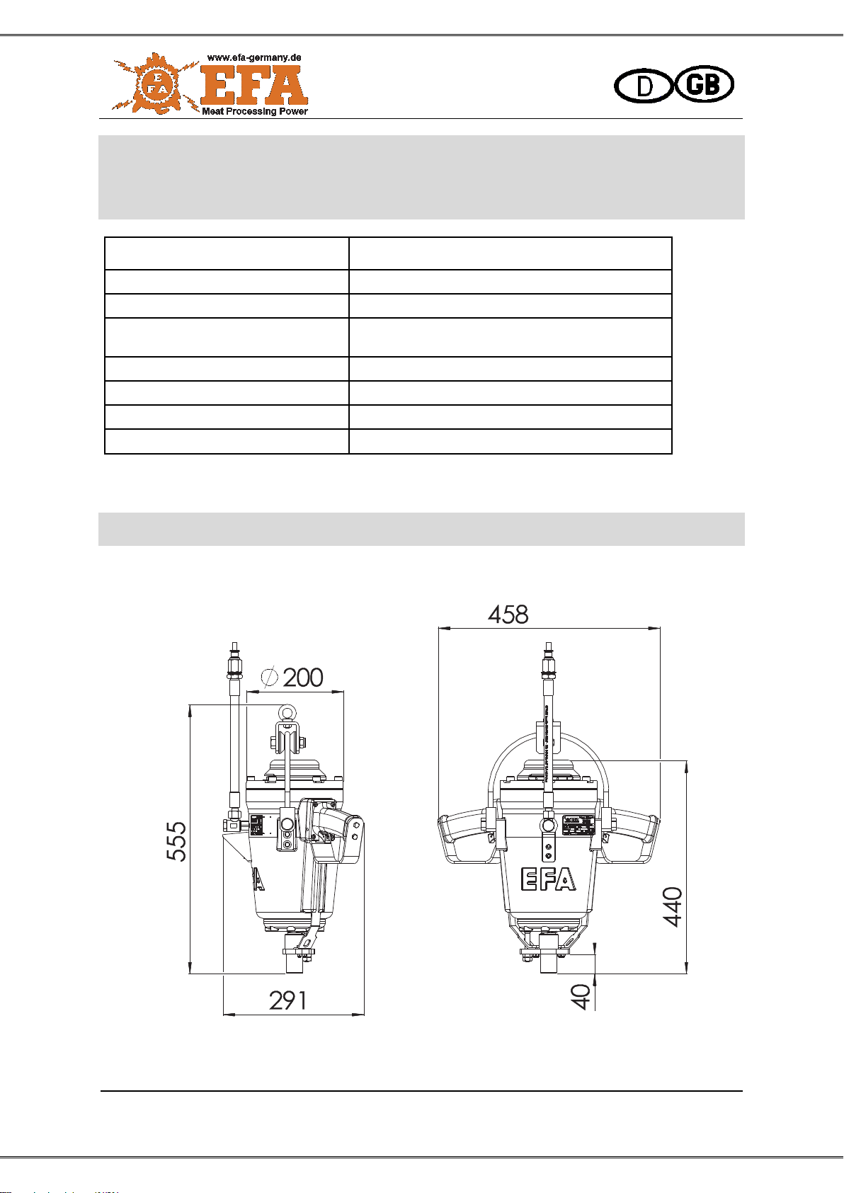
Abmessung L / W / H / Dimension
458 x 291 x 447 mm
Gewicht / Weight
19 kg
Table 2 Technische Daten / Table 1 Technical Data
A2 Maßblatt / Dimension sheet
Schmid & Wezel
Seite / Page
13 of 13
Stand / Version
04 / 2017
B Installationsplan / Installation Plan
Fig. 4 Installationsplan / installation plan
Table of contents
Other EFA Industrial Equipment manuals


Popular Industrial Equipment manuals by other brands


Festo
Festo FKC Series Assembly instructions

CFE
CFE LFP4820S3 Product user manual

Emerson
Emerson Daniel 3410 Series Maintenance and troubleshooting manual

Sonny's
Sonny's SF50 owner's manual

EVAPCO
EVAPCO Mr. GoodTower EAW-FD Series Additional Installation, Operation and Maintenance Instructions

Festo
Festo FLSM Series operating instructions