STIF VIGIBELT CDM80 User manual

INSTRUCTION MANUAL GB –1/6
www.stifnet.com - DOC NO. BE0455020-A
USE
- The VIGIBELT® CDM80 is a belt alignment control system for buckets elevator. It helps prevent friction between the
strap and the inside of the elevator leg. The VIGIBELT® CDM80 detector must be installed in pairs on the side of
the riser leg of the elevator and just above its foot. If the elevator is more than 20m high, it is then recommended to
add a pair of VIGIBELT® CDM80 just below the head, still on the riser.
- We recommend placing an EAZY> DETEC target (STIF product) every 30 meters on the belt to allow precise
detection by the VIGIBELT® CDM80. The EAZY> DETEC metal target should be installed in place of a plastic
bucket.
DESCRIPTION
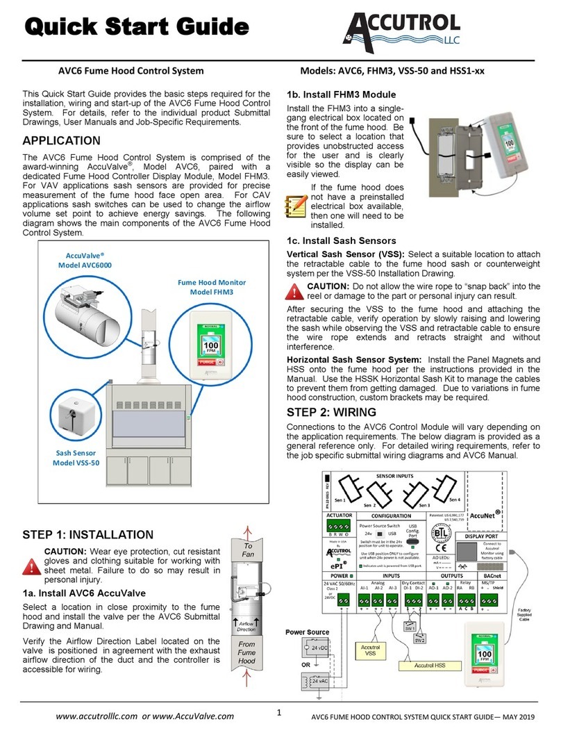
- The VIGIBELT® CDM80 is composed of two sensors, an calibration tool, a background metal sheet and the fixing
screws.
Possible adjustment for the VIGIBELT®CDM80
- The VIGIBELT® CDM80 is intended to be programmed for detection distances of 15 to 35 mm (with a pitch of 5mm)
between the inside of the lift leg and the target bucket
PRECAUTIONS
The VIGIBELT®CDM80 kit must be installed, connected and put into service only by competent personnel. The
staff must have electrical authorizations, know the regulations and provisions concerning the installation of these
devices, especially for the Ex II3D version integrated in ATEX zones.
- Carry out beforehand an electrical connection study to install the VIGIBELT®CDM80 (standard electrical diagram,
power supply and electrical protection, plc control, ATEX zones).
- Check that the temperature range of use of the VIGIBELT®CDM80 (variable according to version) corresponds
to your application.
- Check during the first commissioning of the bucket elevator in the handling phase, that there is no sealing defect
(dust leak) between the sheath of the elevator and the VIGIBELT®CDM80.
- Bring the bucket elevator or belt conveyor to a stop (off-powored) before any installation or intervention on the
VIGIBELT®CDM80 (intervention information to be indicated on the machine).
Z.A. de la lande - 49170 Saint-Georges-sur-Loire - France
Head office, purchasing and factory: tel: +33 2 41 72 16 80 - Fax +33 2 41 72 16 85
France Export Sales Service: tel.: +33 2 41 72 16 82 - Fax +33 2 41 39 32 12
email: sales@stifnet.com - Website: www.stifnet.com
SAS with a capital of € 800,000 - R.C.S. Angers B 328 876 503 - 84B12 APE 2511Z - VAT number FR 35 328 876 503
2X CDM80
1X FLAT BACK SHEET
M6 SCREWS
1X CALIBRATION
TOOL

INSTRUCTION MANUAL GB –2/6
www.stifnet.com - DOC NO. BE0455020-A
INSTALLATION
- Following figure A, make two symmetrical openings on each side of the elevator (square opening of 112mm + 4
holes on Ø6.5 on a square of 126mm)
Target EAZY>DETEC
X
s
Ji
Ep
Opening 112mm
4 holes Ø6.5 on 126mm
200
Lift Sheath
Ep. = thickness of the sheath
Ji = clearance between the inside of the sheath and
the strap
S = thickness of the strap
TARGET
BUCKET
POSITION OF THE OPENING
L90 - H80
X = Ep. + Ji + S + 60
L150 - H110
X = Ep. + Ji + S + 75
Figure A
Careful: obligation to install an EAZY> DETEC
metal bucket every 30 meters of belt on
elevators equipped with plastic or stainless-
steel buckets
Target EAZY>DETEC

INSTRUCTION MANUAL GB –3/6
www.stifnet.com - DOC NO. BE0455020-A
- First assemble the M6 pan-head screws with the low nuts on the sheath (clamping torque 6N.m).
Connect the VIGIBELT® CDM80 according to the electrical diagram B or C:
NC detector = positive safety, permanent control of the correct functioning of the sensor
The loss of signal indicates that there is a problem with, Belt misalignment
Electric wire cut
3-wire/NC connection scheme B
colours
BN = Brown
BU = Blue
BK = Black
PVC cable 2m for ATEX zone and not ATEX 3x0.34mm²
2-wire connection scheme C
colours
BN = Brown
BU = Blue
PVC cable 2m for non ATEX 2x0.34mm²
For low voltage sensor, ATEX or not
- 3-wire cable connection
- L=2m cable
- Voltage 12-24V DC
- Voltage limits, including ripple, 10-36V DC
- Switching power ≤200 mA
- temperature Operating: -25... 70°C (not ATEX)
- temperature Operating: -20... 60°C (ATEX)
- Protection - IP68
Caution: Any connection must be made outside the
ATEX zone
For multi-voltage sensor, out of ATEX zone
- 2-wire cable connection
- L=2m cable
- Voltage 24... 240V AC/DC
- Voltage limits, ripple included 20... 264V AC/DC
- Residual voltage at nominal I ≤5.5V
- Switching power 5... 200 mA AC/DC
- temperature Operating: -25... 70°C
- Protection - IP68
It is imperative to put in series with the load a fast-
acting fuse of 0.4A
This pre-assembly easier the installation
of the VIGIBELT® CDM80

INSTRUCTION MANUAL GB –4/6
www.stifnet.com - DOC NO. BE0455020-A
- Define the detection range of VIGIBELT®CDM. To do this, first identify the safety zone that corresponds to the
minimum distance that the strap must never cross during a setback defect. Then identify the distance between
the edge of the strap and the edge of the metal target (Bucket or EAZY DETECT). These two values, safety
zone + edge-to-edge distance allow you to choose the detection range to program, i.e. 15, 20, 25, 30 or 35mm.
Sample application:
zone Security = 10mm + distense from board to edge = 20mm; program the detection distance of the
VIGIBELT®CDM at 30mm
LEARN THE DISTANCE OF THE DETECTION TARGET:
DO NOT TURN OFF THE POWER DURING THIS OPERATION
- Remove and keep the access screw to the learn button
- Position the adjustment element with the desired remote
background sheet on the sheath then put the sensor.
- Press with a 4-sided screwdriver and hold down the button, this first
triggers the extinction of the green diode, and then about 3 seconds
after it turns on again
- Release the button,
- The green diode flashes 3 times to indicate that learning is in
progress. 2 possibilities are then available:
➢The green diode remains on : it indicates that the detector
has recorded the position of the object correctly and is ready
to work. Any object passing through its detection field at this
distance will be detected.
➢The green diode flashes very quickly: distance learning
has failed.The requested distance is outside the allowed
range or absence of object in front of the detector. Or the
power was cut off after learning about the environment.
Perform a RESET and resume from the learning phase.
figure D
Calibration tool
with distance
determine in
advance
Programmable detection range
from 15 to 35
Learn button access screw
=
3 Flashes
3s
Finite learning
Fast
Flashe
s
=
3 Flashes
3s
Learning failed

INSTRUCTION MANUAL GB –5/6
www.stifnet.com - DOC NO. BE0455020-A
- After the detection distance learning operation, you should check that the VIGIBELT® CDM80 is in mode "1"
in normal operation and in mode "2" in the presence of a metal target (see LED status below).
- Remove the adjustment tool and reposition the CDM80 on the opening, tighten the four M6 locknuts with
type L washers (clamping torque 4N.m) according to diagram E. Now it is put into operation.
Note: to make another adjustment, it is necessary to reset each detector by following the instructions
below, then resume steps 1 and 2 of the programming.
- Disassemble the CDM80 from the sheath to remove it from any metal mass.
- Press and hold the detector button, it turns off the green diode for 3 seconds, then it turns on for 4 seconds,
then turns off again. Release the button
- The detector is now without a resident program. You can resume the detection distance learning operation.
1_Normal operation: GREEN DIODE ON AND ORANGE ON (contact closed)
2_Object in the detection field: GREEN DIODE ON AND ORANGE Off (open contact)
3_Electrical fault: NO DIODE LIT
Led observation
window during sensor
setting
Return the access screw
to the learn button
Figure E
3s
4s
3
Flashes
=
RESET OK

INSTRUCTION MANUAL GB –6/6
www.stifnet.com - DOC NO. BE0455020-A
CONTROL & PERIODIC MAINTENANCE
1) To ensure the functional integrity of the VIGIBELT®CDM80, you must schedule periodic inspections. The
frequency of inspections must be sufficient to avoid dangerous situations (situations that affect the intrinsic
functioning of the VIGIBELT®CDM80).
2) During these inspections, check that the VIGIBELT®CDM80 are not affected by the following defects: dust layer
>2mm, dust leakage between the sheath of the elevator and the VIGIBELT®CDM80, non-operational power-on LED,
degraded electrical wiring, shocks on the envelope of the VIGIBELT®CDM80, etc...
3) In the case of one or more defects found, you must proceed with the restoration in order to correct the defect(s)
before you can use the bucket lift or belt conveyor again.
4) Only personnel trained and authorized in maintenance procedures for these equipments are able to carry out
inspections for the VIGIBELT®CDM80.
DISPOSAL
When dismantling the VIGIBELT®CDM80, the user must ensure the proper disposal of this device and hand over
to the specialized harvesting centers the components according to their nature (stainless steel, electrical
equipment, seal, etc.).
In the event that the VIGIBELT® CDM80 kit is used, controlled, under conditions contrary to the precautions
described in this instruction manual, STIF declines all responsibility for damage caused to man, animal,
environment, material property.
Table of contents
Popular Control System manuals by other brands
Rockford Fosgate
Rockford Fosgate SSC-1500 GEN II installation manual

NICOR
NICOR NLC Commissioning Guide
Fagor
Fagor 8055 M Programming manual
Lutron Electronics
Lutron Electronics myRoom Operation and maintenance manual
Avanza
Avanza aSL.1503 aSmart Lite installation manual
Porcheson
Porcheson MK2 Series user manual
LG
LG PCRCUDT2 user manual
CSI
CSI COMPACT CIP Installation operation & maintenance
Fancom
Fancom 743 user manual
Distech Controls
Distech Controls DA-020S Series Hardware installation guide
Murphy
Murphy MURPHYMATIC A900 Series Installation and operating manual

Raven
Raven AccuBoom Parallel Installation Manual

