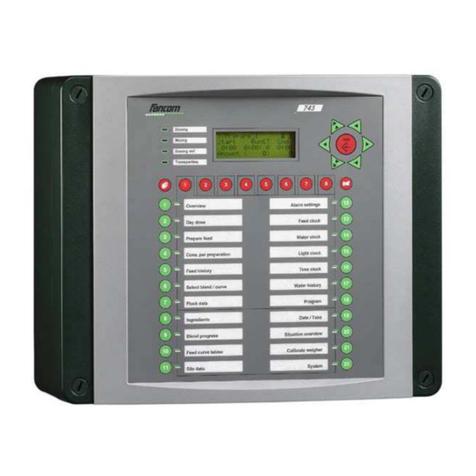
Fancom 743 User manual

GB
743
USER MANUAL
VERSION C3

Fancom 743 Copyright
Fancom B.V. Limited Warranty Statement
Fancom expressly warrants each new product manufactured by it to be free from defects in material or
workmanship for two years from the date of initial installation by or for the original purchaser, but in no
event shall such period be greater than two years and three months from the date of initial shipment of
the product from the manufacturer's facility. The following warranties are in lieu of any and all
representations and warranties, express or implied, including the implied warranties of merchantability or
fitness for a particular purpose, whether arising from statute, common law, custom or otherwise. Fancom
shall not be liable for any special, consequential or incidental damages resulting from the use of any of the
products or caused by any defect, failure or malfunction, whether a claim for such damage is based upon
warranty, contract, negligence or otherwise, and in no event shall Fancom be liable for any damages in
excess of the amount paid for the products. In the event a defect is found by the anufacturer to exist
within this period, the anufacturer will, at its option, (a) repair or replace such product free of charge,
F.O.B. the factory of manufacture, or (b) refund to the original purchase price to the original purchaser, in
lieu of such repair or replacement. Labour costs associated with the replacement or repair of the product
are not covered by the anufacturer.
WARNING: Independent alarm installation
Like all mechanical and electronic devices, the Fancom Control Unit may fail. Thus, when the Fancom
Control Unit is controlling the environment for confined livestock, it is highly recommended by Fancom
that an independent alarm system be installed. The Fancom Control Unit does provide a connection port
designated for either make or break contact for the sounding of an alarm condition (please refer to
installation guide for location). Failure to comply with the above warning may result in loss of product
and/or profits, for which Fancom is not responsible or liable.
January, 2002.
All rights reserved. Reproduction of any part of this manual in any form whatsoever without Fancom’s
express written permission is forbidden. The contents of this manual are subject to change without notice.
All efforts have been made to assure the accuracy of the contents of this manual. However, should any
errors be detected, Fancom would greatly appreciate being informed of them. The above notwithstanding,
Fancom can assume no responsibility for any errors in this manual or their consequence.
Copyright 2002 Fancom B.V.
Panningen, the Netherlands
GB110102
GB110102GB110102
GB110102
ODIFICATIONS RESERVED
ODIFICATIONS RESERVEDODIFICATIONS RESERVED
ODIFICATIONS RESERVED
Art. Nr. A5911215
Art. Nr. A5911215Art. Nr. A5911215
Art. Nr. A5911215
Al ays keep this manual by your computer
Al ays keep this manual by your computerAl ays keep this manual by your computer
Al ays keep this manual by your computer

Fancom 743 EC Declaration of compliance
EC Declaration of compliance
anufacturer :
Fancom B.V.
Address :
Industrieterrein 34
City :
Panningen (the Netherlands)
Hereby declares that the:
743
743743
743
satisfies the following standards or other standard document(s):
Emission characteristics were assessed according to standard NEN-EN 50081-1. The
susceptibility was established in accordance with the requirements of the generic immunity
standard NEN-EN 50082-2. The low voltage guide according to NEN-EN-IEC 60950.
Satisfies the conditions set out in:
1. The Low Voltage Guideline (Directive 73/23/EEG, as last amended by the Directive
93/68/EEG).
2. The E C Guideline (Directive 89/336/EEG, as last amended by the Directives 92/31/EEG
and 93/68/EEG).
Place:
Panningen
Date:
11-1-2002
(Signature)
(Signature)
(Name of the signatory 1)
ath Stammen
(Name of the signatory 2)
Wout Hoolboom
(Occupation of the signatory 1)
Research manager
(Occupation of the signatory 2)
Project anager feeding systems

Fancom 743 Table of contents
Table of contents
About this manual
1. Introduction..................................................................................................................................1
2. Safety instructions and warnings ................................................................................................2
3. Working ........................................................................................................................................3
3.1 Example of an installation....................................................................................................3
3.2 Parts of the installation ........................................................................................................3
4. Operation......................................................................................................................................5
4.1 Front .....................................................................................................................................5
4.2 Display (A) ............................................................................................................................6
4.3 Keyboard (B) .........................................................................................................................6
4.4 Alarm and index keys (C) .....................................................................................................8
4.5 Storage silo keys (D) .............................................................................................................9
4.6 Function keys (E)..................................................................................................................9
4.7 LEDs (F)................................................................................................................................9
5. Function keys .............................................................................................................................10
5.1 General................................................................................................................................10
5.2 Overview.............................................................................................................................10
5.3 Preparation per day............................................................................................................12
5.4 Preparation actions.............................................................................................................13
5.5 Consumption per preparation action..................................................................................15
5.6 Feed history ........................................................................................................................16
5.6.1 7 day consumption ....................................................................................................16
5.6.2 7 days per animal......................................................................................................16
5.6.3 Total consumption.....................................................................................................17
5.6.4 Total consumption.....................................................................................................17
5.7 Select blend/curve...............................................................................................................18
5.7.1 Select blend/curve .....................................................................................................18
5.7.2 Current blend............................................................................................................18
5.7.3 Offset blend ...............................................................................................................19
5.7.4 Current curve............................................................................................................20
5.8 Flock data............................................................................................................................21
5.8.1 Number of animals....................................................................................................21
5.8.2 Setting up a flock ......................................................................................................21
5.9 Ingredients..........................................................................................................................22
5.9.1 Ingredient list............................................................................................................22
5.9.2 Replace ingredient ....................................................................................................22
5.9.3 Additive .....................................................................................................................23
5.9.4 Mix ingredient...........................................................................................................23
5.10 Blend progress ....................................................................................................................24
5.11 Feed curve tables ................................................................................................................25
5.12 Silo data ..............................................................................................................................26
5.12.1Silo overview .............................................................................................................26
5.12.2Silo update.................................................................................................................26
5.13 Alarm settings.....................................................................................................................27
5.13.1Feeding......................................................................................................................27
5.13.2Water clock................................................................................................................28
5.13.3Minimum stock .........................................................................................................29
5.13.4Additives....................................................................................................................29
5.13.5External alarm..........................................................................................................29
5.14 Feed clock............................................................................................................................30
5.15 Water clock..........................................................................................................................31
5.15.1Day water dosing ......................................................................................................31
5.15.2Water clock................................................................................................................31
5.16 Light clock...........................................................................................................................32

Fancom 743 Table of contents
5.17 Time clock ...........................................................................................................................34
5.18 Water history ......................................................................................................................35
5.19 Program ..............................................................................................................................35
5.20 Date and time......................................................................................................................36
5.21 Situation overview ..............................................................................................................37
5.22 Calibrating the weigher......................................................................................................39
6. Alarm..........................................................................................................................................40
6.1 Switching the alarm OFF...................................................................................................40
6.2 Feed alarms.........................................................................................................................41
6.3 System alarms.....................................................................................................................42
6.4 Alarm history......................................................................................................................42
7. Password.....................................................................................................................................43
APPENDIX 1: enu overview

Fancom 743 About this manual
About this manual
This manual aims to supply the user with the information necessary for a step by step insight
into the working and operation of the computer. Read this manual carefully chapter by chapter.
After the manual has been read, data can be entered in the computer.
This manual has been written by Fancom for the computer user. An installer’s manual is also
available for the installer. If you have any questions regarding the computer, please do not
hesitate to contact your Fancom dealer.
The following symbols are used in this manual:
Suggestions, advice and notes with additional information.
Caution
CautionCaution
Caution
The product could be damaged, if the procedures are not followed carefully.
Caution
CautionCaution
Caution
Life threatening situation, if the procedures are not followed carefully.

Fancom 743 1. Introduction
1
1. Introduction
The Fancom 743 is a feed mixing computer for the poultry sector. It is suitable for fully
automatic control of a feed mixing installation.
aximum installation size
aximum installation sizeaximum installation size
aximum installation size
♦ 12 stock silos
♦ 12 ingredients
♦ 1 weigher, possibly with mixer
♦ 1 hopper including proximity switch
♦ 16 storage silos (incl. prox. feedback)
♦ 4 additives
♦ 2 circuit auger controls
♦ 16 storage silo selection valves
♦ 16 storage silo augers
♦ 16 feed clocks
♦ 16 water clocks
♦ 16 pulse inputs for the water meter
♦ 16 light clocks, controllable or on/ off
♦ 16 extra time clocks
♦ 16 pulse relays
Communication
CommunicationCommunication
Communication
The computer can be connected in a network or serial communication loop (using a
communication connector print). The 743 computer can be operated by a remote Personal
Computer.

Fancom 743 2. Safety instructions and arnings
2
2. Safety instructions and arnings
Read the safety instructions carefully before operating the system. The installation of the
computer and trouble shooting must be carried out by an authorized technician/installer,
according to the prevailing standards.
Caution
CautionCaution
Caution
1. Check your computer regularly for correct functioning. It is an electronic apparatus and
should therefore give an alert during any system failures. Fancom has done everything
electronically possible to ensure that an alarm is given during any such failure.
Unfortunately, this cannot be 100% guaranteed because not all circumstances are under
Fancom’s control.
2. Fancom takes no responsibility for any possible damage as a result of incorrect settings and a
non- or partially functioning installation.
3. Ask your installer if the alarm contacts of each computer have been connected to a separate
alarm system circuitry.
4. Check the computer regularly for possible damage. Any damage should directly be reported
to your installer.
A damaged computer could be dangerous!
5. Do not use running water (high pressure cleaners) to clean your computer.
The computer is water resistant, not waterproof!
6.
Important!
Important!Important!
Important!
Do not switch off the computer when houses are unoccupied; this is to protect the computer
against condensation.

Fancom 743 3. Working
3
3. Working
3.1 Example of an installation
Fig. 1: Example of an installation
3.2 Parts of the installation
Ingredient
The raw material in the silo. The 743 prepares blends which can consist
of several ingredients. The various ingredients are transported to the
weigher using augers.
Ingredient silo
Silo used to store ingredients.
Silo auger
Used for transport between silo/tank and weigher.
Blend
A blend is a mixture of various ingredients to be fed as a finished
product. It can consist of maximum 12 ingredients.
Weigher
A weigher used to weigh the ingredients and compose the blend. Various
types of weigher (batch) are possible, with or without mixer, depending
on the type of installation. Depending on the weigher type, with or
without hopper.
ixer
echanism used to mix the ingredients in the weigher.
Circuit auger
Used for transport from the weigher to the storage silo valve or storage
silo auger.
Tanks with additives
Ingredient silo
Dosing in auger
Dosing in auger
Storage silo
Circuit auger
Weigher
Hopper

Fancom 743 3. Working
4
Storage silo selection
valve
Used to select the storage silo inlet or auger.
Storage silo (auger)
Used for transport from the weigher, possibly from the circuit auger or
selection valve, to the storage silo.
Storage silo
Silo used to store the prepared blend. One storage silo can be assigned
per section.
Blending process
Blending processBlending process
Blending process
The demand for feed preparation originates from the storage silo. The ingredients are
transported to the weigher via dosing in augers. Ingredient dosing in is based on weight
increase. Additives, e.g. minerals, can be added at the same time as the ingredients are being
dosed in based on pulses or time.
If the weigher has a mixer, the ingredients and/or blend can be (after) mixed for a certain time.
The blend is dosed out directly from the weigher or hopper via one or more augers, or
transported to a storage silo via a dosing out system.
aximum sensor
aximum sensoraximum sensor
aximum sensor
The
maximum sensor
is used to fill the storage silo. As soon as the feed covers the maximum
sensor a signal will be sent to the computer. The computer will not start a dosing in action again.
When the feed level in the storage silo drops below the maximum sensor, the computer will be
able to prepare more feed. The number of portions to be prepared also depends on whether there
is a filling level sensor and if this sensor is covered or not.
The installer should mount the sensor at the correct height in the storage silo. Once the
maximum level has been reached, the portions being transported from the weigher and/or
hopper should still be able to fit into the storage silo.
Filling level sensor and minimum sensor
Filling level sensor and minimum sensorFilling level sensor and minimum sensor
Filling level sensor and minimum sensor
An extra sensor, a
filling level sensor
, can be used to fill the storage silo more quickly and
accurately. As soon as the filling level sensor is covered, the computer will adjust the maximum
number of portions being transported.
A
minimum sensor
can also be used. This will send an alarm signal to the computer if the
storage silo stock has not been used up, after the last feeding time at the end of the day.

Fancom 743 4. Operation
5
4. Operation
4.1 Front
In order to operate the Fancom 743, it is necessary to know the functions of the various keys and
LEDs. Fancom divides the front into six parts; A, B, C, D, E and F.
A = Display
B = Keyboard
C = Index and alarm key
D = Storage silo keys
E = Function keys
F = LEDs
Fig. 2: Front 743
A
F
B
C
D
C
E

Fancom 743 4. Operation
6
4.2 Display (A)
The front of the 743 computer has an illuminated display consisting of 4 lines, each with 20
positions.
4.3 Keyboard (B)
Example 1: Change the setting
Prepare feed Status
into
SKIP.
1. Press
Prepare feed
.
2. Press 2×.
3. Press .
4. Select SKIP from the table.
5. Press .
Prepare_1 1
START at 10:00
Blend FEED+WHEAT
Amount (.....) .....
•
During changes increase
value ×10.
•
During text changes select
the next group of characters.
• Increase index.
• Feed history: TODAY
YESTERDAY.
•
During changes cursor to the
left
• Return to previous menu.
•
During changes increase
value ×1.
• To previous line.
• Dur
ing changes cursor to the
right.
• Open sub menu.
•
During changes decrease
value ×1.
• To next line.
•
During changes decrease
value ×10.
•
During text changes select
the previous group of
characters.
• Decrease index.
•
Feed history: YESTERDAY
TODAY.
Changes:
start and confirm
SKIP
BLOCKED
FREE

Fancom 743 4. Operation
7
Example 2: Set the number 5562 at
Flock data 2 Setup flock Number set up.
1. Press
Flock data
.
2. Press 1×, then .
3. Press 2×, 5×, 5×, 2×, 6× and 2×.
4. Press .
Example 3: The example below shows how to change text. E.g. at key
Ingredients 1.
Ingredient list Name
change the name from INGR.1 to EAL.
Groups
GroupsGroups
Groups
1
11
1
2
22
2
3
33
3
4
44
4
5*
5*5*
5*
0 A a ←
! 1 B b ü
" 2 C c é
# 3 D d ä
$ 4 E e À
5 F f c
& 6 G g |
' 7 H h è
( 8 I i ö
) 9 J j û
* : K k y
+ ; L l o
, < m ñ
- = N n a
. > O o e
/ ? P p z
Q q -
R r α
S s β
T t π
U u Σ
V v µ
W w Ω
X x ∞
Y y •
Z z ε
[ { °
\ |
] }
^ →
The characters from group 5 are language dependent.
If the F-Central program is used, some characters on the PC screen may differ.
Select
previous group
Select
next group
Select next
character from group
Select previous
character from group

Fancom 743 4. Operation
8
4.4 Alarm and index keys (C)
Index key
Index keyIndex key
Index key
If there is more data of a similar type, use this key to go to a higher/lower number.
Example: At function key
Cons. per preparation
select the data of the 22nd
preparation action.
1. Press
Cons. per preparation
.
2. Press .
3. Press 2× and 1×.
4. Press .
Instead of , and can also be used to increase/decrease the index number
by 1.
Alarm key
Alarm keyAlarm key
Alarm key
This key supplies more information about an alarm during an alarm situation. This
key also contains an alarm history (see chapter 6).

Fancom 743 4. Operation
9
4.5 Storage silo keys (D)
These keys are used to select the storage silo for which values are to be entered or displayed.
Storage silos 1 thru 8 are selected by pressing the key concerned. A light in the key indicates
which storage silo has been selected.
Storage silos 9 thru 16 are selected using . If, for example, storage silo 12 has been selected,
all lights except the light in key 4 are on.
4.6 Function keys (E)
The front of the computer has 22 function keys. The display gives more information about the
subject of the key concerned. A light in the key indicates which key has been selected.
4.7 LEDs (F)
Dosing in
Light is on when the ingredients are being dosed into the weigher.
ixing
Light is on when the mixer in the weigher is active.
Dosing out
Light is on when the blend is being dosed out.
Transporting
Light is on when the blend is being transported from the weigher to the
storage silo.
9 10 11 12 13 14 15 16

Fancom 743 5. Function keys
10
5. Function keys
5.1 General
There are two groups of settings on the front:
Keys thru and thru Storage silo dependent settings. These settings are
made per storage silo (maximum 8 times).
Storage silo keys:
Use these keys to select the storage silo for which
settings are to be made.
Keys thru and thru General settings. These settings are identical for all
the storage silos and only have to be made once.
5.2 Overvie
PREPARE
PREPAREPREPARE
PREPARE
The computer can prepare feed in three ways:
Register The computer prepares feed the whole day at the set start times and transports
the feed based on the maximum sensor in the storage silo.
Dose The computer starts feed preparation at set start times based on the maximum
sensor in the storage silo. The computer prepares a fixed amount of feed per
preparation action.
Distribute The computer starts feed preparation at set start times based on the maximum
sensor in the storage silo. The computer prepares a fixed amount of feed per day;
the feed amount can differ each preparation action.
Prepare 1
Started at 10: 0
Blend FEED+WHEAT
Amount( 0) 500
Feed clock 1
Start at 0:00
>
Water clock 1
Start at 10:50
Amount( 0) 200
>
Light clock 1
Start at 10:00
Light level (%) 60
>
Time clock 1
Start at 0:00

Fancom 743 5. Function keys
11
Start(ed)
The time at which blend preparation will start (
Start
) or has
Started
.
Blend
The blend the computer is preparing or going to prepare.
Amount
This readout depends on the set preparation program,
(
Program Prep. feed
):
REGISTER The value between brackets is always 0. This is followed by the
amount of feed already transported to the storage silo today.
DOSE The amount of feed the computer will prepare during this
preparation action is shown between brackets. This is followed
by the amount of feed already transported to the storage silo
during this preparation action.
DISTRIBUTE
The amount of feed the computer will prepare today is shown
between brackets. This is followed by the amount of feed
already transported to the storage silo today.
FEED CLOCK
FEED CLOCKFEED CLOCK
FEED CLOCK
Start(ed)
The time at which the connected feed system (e.g. a feed chain) should start
(
Start
) or has
Started
. This start time has been entered at function key
Feed clock
.
WATER CLOCK
WATER CLOCKWATER CLOCK
WATER CLOCK
Start(ed)
The time at which the watering system should start (
Start
) or has
Started
. This
start time has been entered at function key
Water clock
.
Amount
This readout depends on the set water program(
Program Water clock
):
REGISTER The value between brackets is always 0. This is followed by the
amount of water already given today (litres).
DOSE The amount of water the computer will give during this cycle is
shown between brackets. This is followed by the amount of
water already given during this cycle.
LIGHT CLOCK
LIGHT CLOCKLIGHT CLOCK
LIGHT CLOCK
Start(ed)
The time at which the light should activate (
Start
) or has activated (
Started)
.
This start time has been entered at function key
Light clock
.
Light level (%)
The light intensity in %.
TI E CLOCK
TI E CLOCKTI E CLOCK
TI E CLOCK
Start(ed)
The time at which the time clock should start (
Start
) or has
Started
. This start
time has been entered at function key
Time clock
.

Fancom 743 5. Function keys
12
5.3 Preparation per day
EIGHT FEED CURVES AND EIGHT BLEND OPTIONS
EIGHT FEED CURVES AND EIGHT BLEND OPTIONS EIGHT FEED CURVES AND EIGHT BLEND OPTIONS
EIGHT FEED CURVES AND EIGHT BLEND OPTIONS
In the feed curve tables 10 bending points have been entered for the amounts to be fed. The
composition of the blends to be dosed has been entered at blend progress (see sections 5.10 and
5.11).
Per animal
The amount of feed per animal. If the feed curve table has been filled in and
the
Blend day
is a number other than 0, the computer will automatically
calculate this amount from the current feed curve. In other cases enter the
amount per animal here. The computer will then automatically calculate the
total amount of feed to be dosed (
Feed amount
). If a feed curve is used, the
daily amount can be corrected here if necessary. This correction value can be
read out at
Offs. curve.am.
This setting is only important with
Dose
and
Distribute.
Feed amount
The total amount of feed to be prepared for this day. The computer will
automatically calculate this amount from the entered amount per animal. This
amount can also be entered and the computer will automatically calculate the
amount per animal.
This setting is only important with
Dose
and
Distribute.
Blend day
If feed curves are not used a 0 will appear here.
In other cases the number of weeks and days elapsed will be shown between
brackets, followed by the total number of days.
The computer uses this value to locate the position in the feed curve and to
determine the current feed amount.
>>Day dose 1
Per animal 0.000
Feed amount 0
Blend day (00.0) 0
>>Day dose 1
Offs.curve am. 0.000
>>
>>Day dose 1
Additive_1 ADDIT.1
0.000 per 0
Day total 0.000
>>Day dose 1
Copy to all
storage silos?
NO

Fancom 743 5. Function keys
13
Offs.curve. am
The amount of feed to be dosed per animal can be increased (positive value) or
decreased (negative value) here. This allows more or less feed to be given than
the curve amount. As soon as
Offs.curve am.
is reset to 0, the computer will
dose the amount of feed originally set per animal.
The computer will reset the offset to 0 after a blend day has been
changed or a new flock has been set up.
Additive
Enter the amount of additive (accurate to the gram) that should be added per
kg blend. Adding will be based on time or pulses. Use to select the next
additive.
Day total
The total amount of additive the computer will add today.
Copy to all
storage silos?
Set to YES to copy all settings made for this storage silo to the other storage
silos.
5.4 Preparation actions
Start
The start and run times can be entered for 24 preparation actions (maximum).
The computer will automatically calculate the corresponding end times. Use
to select the next preparation action.
Enter the start time for this preparation action in hours and minutes.
>>Prepare_1 1
Start RunT End
0:00 0:00: 0 0:00
Amount ( 0) 0
>>Prepare_1 1
Status FREE
B.rhythm( 0) 0
Prep.time 000
>>Prepare_1 1
AddI ADDIT. 1 from
1st INGRED.
Amount 0.250
>>Prepare_1 1
AddII ADDIT. 2 from
2nd INGRED.
Amount 0.1 5
>>Prepare_1 1
Copy to all storage
silos?
NO

Fancom 743 5. Function keys
14
RunT
Enter the run time for this preparation action in hours, minutes and seconds.
End
The calculated end time for this preparation action. The computer calculates
this value using the entered start and run times.
Amount
The readout between brackets depends on the set form of preparation: with
register the value 0 is always shown; with dose the amount of feed the
computer will prepare during this preparation action will be shown; with
distribute the amount of feed the computer will prepare today. Following the
brackets is the amount of feed already prepared for the current preparation
action.
Status
The preparation action status. There are four possibilities:
FREE Status must be FREE in order to prepare feed. This refers to an
active feed action.
BLOCKED The computer will not activate this preparation action as long as
status is BLOCKED.
SKIP The computer will skip this preparation action for this day. When
the run time has elapsed the computer will automatically reset
the setting to FREE.
ONCE After a feed action the status will be BLOCKED again.
B.rhythm
An animal’s feeding pattern is not constant throughout the day. The feed
amount can be adjusted per preparation action. If a negative percentage (e.g.
-5%) is entered, the computer will prepare 5% less feed during this action. A
positive percentage (e.g. +5%), means that 5% more feed will be prepared. The
amount originally to have been prepared during this action will be shown
between brackets. The sum of the biorhythm percentages must be 0!
Prep. time
The amount of time required for this preparation action.
AddI/II ...
from ...
A maximum of two additives can be added per preparation action. Select here
which additives and from which ingredient onwards they should be added by
the computer.
Amount
The calculated amount of additive to be added by the computer during this
preparation action.
Copy to all
storage silos?
Set to YES to copy all settings made for this storage silo to the other storage
silos.
Other manuals for 743
1
Table of contents
Other Fancom Control System manuals

Fancom
Fancom LUMINA 41 User manual

Fancom
Fancom 743 User guide

Fancom
Fancom LUMINA 71 User manual

Fancom
Fancom VLR.6 User manual

Fancom
Fancom IMS User manual

Fancom
Fancom WEBLINKBOX VERSION A2 User manual

Fancom
Fancom FB.1 User manual

Fancom
Fancom 750 User manual

Fancom
Fancom ITM-iF User manual

Fancom
Fancom MRK.2 User manual
Popular Control System manuals by other brands

WABCO
WABCO OptiTire System description

Extron electronics
Extron electronics TouchLink TLC Pro 526M Series user guide

Cisco
Cisco 1121 quick start guide

Mountz
Mountz E-DRIV MD-Series CALIBRATION PROCEDURE

Autonics
Autonics Aptivolt Firmware update guide

Techno CNC Systems
Techno CNC Systems BT1212 user manual