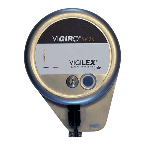
STIF VIGIRO IP26 User manual

INSTRUCTION MANUAL GB –1/3
www.stifnet.com - N° DOC BE0455060-A
USE
-The VIGIRO® IP26 was engineered in order to control the constant speed of a rotative shaft. It is used for the identification
of dangerous under speed and/or the control of the production’s performance.
-It is equipped with a pulses meter which is either connected on a pre-set machine or an independent security module to
identify the nominal pulses’ frequency at the outlet. It is frequently installed on buckets’ elevators, chain conveyors, mixers,
rotary valves, belt conveyor etc.
-The VIGIRO® IP26 gets fixed either directly at the end of the rotating shaft with M12 tapping (M10 optional), either with the
EAZY-FIX (magnetic fixation) for a quick commissioning without tapping.
DESCRIPTION
The VIGIRO® IP26 is a compact device compose of the following components:
1. Protection skin in stainless steel
2. Connecting cable 2m (2 or 3 wires)
3. M12 thread rotative axe in standard fabrication (M10 optional) for the fitting to shaft.
4. Anti-rotation strap
5. Detectable 2-blade propeller (optional 4-blade propeller) located inside the protection
6. Transparent window
Possible adjustment of the VIGIRO® IP26
-Rotative frequency to be respected 0.5….500tr/min or 1…1000 impulsions/min.
Z.A. de la lande - 49170 Saint-Georges-sur-Loire - France
Siège social, achats et usine : tél. : +33 2 41 72 16 80 - Fax +33 2 41 72 16 85
Service commercial France Export : tél. : +33 2 41 72 16 82 - Fax +33 2 41 39 32 12
Email : sales@stifnet.com - Site internet : www.stifnet.com
SAS au capital de 800 000 € - R.C.S. Angers B 328 876 503 - 84B12 APE 2511Z - N° TVA FR 35 328 876 503
5
1
3
6
2
4

INSTRUCTION MANUAL GB –2/3
www.stifnet.com - N° DOC BE0455060-A
PRECAUTIONS
The VIGIRO® IP26 should be installed and connected exclusively by competent personnel. The personnel need to have
electrical accreditation, a knowledge of the regulation and the disposition concerning the installation of those device,
especially for Ex II3D version integrated in ATEX zones.
Perform before head a study of electrical connection to instal the VIGIRO® IP26 (standardized electrical diagram, electrical
power and protection, autopilot, ATEX zones).
Define the under-speed threshold to apply for the security of the bucket elevator or the belt conveyor to avoid any risk of
overheating (ex: Engine stopping under-speed threshold defined at 6% between the speed observed on the driven pulley and
the nominal speed of the driving pulley).
Control that the operating temperature range of the VIGIRO IP26® (variable depending on version) corresponding at
your application.
Verify during the first commissioning of the bucket elevator, in handling stage, that the VIGIRO IP26® stay still and
maintained by its antirotating strap (only the VIGIRO IP26® shaft should be rotating).
Shut down the bucket elevator or the belt conveyor (de-energized) before any intervention on VIGIRO IP26®
(intervention information to be indicated on the machine)
Optional (magnetic fixation without tapping) :
The EAZY-FIX can’t be installed on a stainless-steel shaft.
Ensure that the bearing surface of the shaft is clean and plane.
Take precaution during installation of the EAZY-FIX because its very strong
magnetic force of attraction can cause pinching injury.
CAUTION… The magnetic field of the EAZY-FIX may damage some sensitive
system such as magnetic tracks or tapes, certain watches, etc…
INSTALLATION
Assembly without EAZY-FIX
Perform a M12 tapping (optional M10) at the end of the pulley shaft with a minimal depth of 18mm following drawing
A (Be careful to center the tapping to avoid eccentricity effects in service).
Coat the tapping with removable thread locker, then screw the VIGIRO®IP26 on the pulley shaft with a 16mm open-end
wrench.
Make sure to respect the setting time of the thread lock before using it for the first time.
Assembly with EAZY-FIX (optional)
Coat the tapping with removable thread locker of the optional EAZY-FIX, then screw the VIGIRO®IP26 on the EAZY-FIX
with a 16mm open-end wrench.
Make sure to respect the setting time of the thread lock before using it for the first time.
Finish by fixing the anti-rotation strap without creating tension between the VIGIRO®IP26 and the anchor point.
(M12)
Drawing A
18
M12/M10
Pulley shaft
Thread lock
Thread lock
Magnetic hold
at the end of the shaft

INSTRUCTION MANUAL GB –3/3
www.stifnet.com - N° DOC BE0455060-A
- Electrically connect the VIGIRO®IP26 according to the appropriate diagram.
PERIODIC CHECKS & MAINTENACE
- To guaranty the operational integrity of the VIGIRO IP26®, you must plan periodical inspections. The frequency of
the inspections lust be enough to avoid any dangerous situations (situations that could have an incidence for the
intrinsic functioning of the VIGIRO IP26®).
- During those inspections, check that the VIGIRO IP26®is not affected by the following defect: dust layer > 2mm,
VIGIRO IP26® shaft fixing loose, degraded or loose anti-rotation strap, power-on LED not operational, degraded
electrical wiring, shock on the VIGIRO IP26®casing, etc …
- In the case of one or multiple defects, you must carry the repair in order to correct the defect(s) before you can
use the bucket elevator or the belt conveyor again
- Only personnel trained and authorized in the maintenance procedures for this equipment are able to carry out
inspection of the VIGIRO IP26®.
SCRAPPING
When dismantling the VIGIRO IP26®, the user must ensure that this device is properly disposed of and hand over to
specialized collection centres the components according to their nature (stainless steel, electrical equipment, seals, etc.).
In the event that the VIGIRO IP26® is used, controlled, under conditions contrary to the precautions described in this
instruction manual, STIF declines all responsibility for damage caused to humans, animals, the environment or property.
materials
2 wires connection diagram / NC
Colours
BN = Brun
BU = Blue
PVC cable 2m 2x0.34mm²
3 wires connection diagram / NC
Colours
BN = Brun
BU = Blue
BK = Black
PVC cable 2m for ATEX and non ATEX zones
3x0.34mm²
For low tension sensor, ATEX or not
-Connection by 3-wire cable
-Cable L=2m
-Voltage 12-24V DC
-Voltage limit, including ripple, 10-36V DC
-Switching power ≤ 100 mA
-Operating temperature: -25…70°C (non ATEX)
-20…60°C (ATEX)
-Protection - IP67
Warning: All connections must be made outside the
ATEX zone
For multi-voltage sensor, outside ATEX zone
-Connection by 2-wire cable
-Cable L=2m
-Voltage 24…240V AC/DC
-Voltage limit, including ripple, 20…264V AC/DC
-Residual voltage at I nominal ≤5.5V
-Switching power 5…200 mA AC/DC
-Operating temperature: -25…70°C
-Protection - IP68
It is imperative to put in series with the load a fast-acting
fuse of 0.4A
Table of contents
Other STIF Controllers manuals
Popular Controllers manuals by other brands
Lenze
Lenze 9300 Series System manual
Siemens
Siemens SIMATRIX Programming manual
Sunricher
Sunricher SR-2818-BLACK manual

THOMSON
THOMSON MK68590 Technical manual

Xylem
Xylem Bell & Gossett Hoffman Specialty 1140 Series instruction manual
Pentair Pool Products
Pentair Pool Products MiniMax NT 6800 installation instructions
