Eldes ESIM120 User manual

ESIM120/ESIM320/ESIM320US
USER GUIDEV1.0
DE
ELDES GATE
CONTROLLER
EN


3
INSTALLATION
EN SYSTEMMONTAGE
DE
1 x 1 x 1 x
EN CONTENTS OF PACK
DE INHALT DER PACKUNG
EN NOT INCLUDED
METAL
METALL
>20 cm
FROM THE POWER LINES
VON DEN STROMLEITUNGEN
MIN 20O
MAX 55O

4
PIN
ANT
USB
F1
SIM CARD
M O D E M
SIM STAT
NETW
DEF
AC/DC RELAY1 RELAY2COM Z5 Z4 Z3 Z2 Z1
ANT
USB
F1
SIM CARD
M O D E M
SIM STAT
NETW
DEF
SMS
SMS
****
+1...5
Number NR4:+441700XXXX110 is set.
12
3
5
4

5
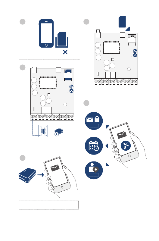
EN 1Disable PIN code request.
2Insert the SIM card into the device’s SIM card slot holder.
3Power up the system and wait unil LED indicator SIM STAT lights up, indicaing
SIM card status. Once the indicator SIM STAT lights OFF, the illuminated
indicator NETW lights up, indicaing that the system has successfully
connected to the GSM/3G network.
4Set the phone number for Admin 1 (NR 1); set date and ime; change the default
SMS password; you may also change the system’s language. Once the system
is conigured, it is ready to use.
5Example of the system’s SMS response to the requested command.
1
5

6
DE 1Deakivieren Sie die PIN-Code Abfrage.
2Legen Sie die SIM-Karte in den SIM-Kartenschlitz des Gerätes ein.
3Schalten Sie das System ein und warten Sie, bis die Anzeige SIM STAT
auleuchtet. Sobald diese “OFF” anzeigt, leuchtet die Anzeige NETW auf und
zeigt damit an, dass das System erfolgreich mit dem GSM/3G Netz verbunden
wurde.
4Geben Sie die Telefonnummer für Admin1 (NR1), das aktuelle Datum und die
Uhrzeit ein, dann legen Sie ein persönliches SMS-Passwort fest. Sie können
auch die Sprache einstellen. Sobald das System koniguriert ist, ist es bereit
zur Verwendung.
5Beispiel für eine SMS-Antwort des Systems auf einen eingegangenen Befehl.
For more system coniguraion, see SMS CONFIGURATION/
Weitere
Informaionen zur System-Konigurierung im Abschnit SMS-
KONFIGURIERUNG.
Before installing the system, please wire it up using the wiring
methods example (see page 7) and connect the antenna (see page 3)/
/ Vor der System-Installierung
verkabeln Sie das System bite wie im Verkabelungsbeispiel (siehe 7)
angezeigt und verbinden Sie die Antenne (siehe Seite 3).
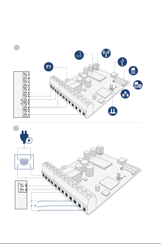
7
GATE AUTOMATION DEVICE
F0 +24vGND
AC/DC
RELAY 1 RELAY 2 COM Z5 Z4 Z3 Z2 Z1
+
-
GATE
AUTOMATION
DEVICE
AC/DC
RELAY 1 RELAY 2 COM Z5 Z4 Z3 Z2 Z1
12...24
AC/DC
EXAMPLE OF WIRING DIAGRAMS/ JUNGIMO SCHEMŲ PAVYZDŽIAI/
/ EJEMPLO DE DIAGRAMAS DE CA
BLEADO/ SCHALTPLANBEISPIEL/
1
2

8
EN RU ES DE
Main Unit & Connectors
Unidad Principal &
Conectores
Haupteinheit & An-
schlüsse
Antenna SMA type connector SMA
GSM/GPRS
Conector de antena ipo
SMA SMA-Antennenanschluss
Mini USB port Mini USB Puerto miniUSB Mini USB-Port
SIM card slot / holder / SIM
Ranura/soporte para
tarjeta SIM SIM-Kartenschlitz
ESIM120 -850/900/
1800/1900 MHz;
ESIM320- 850/900/
1800/1900/2100 MHz
ESIM120 -850/900/
1800/1900 ;
ESIM320- 850/900/
1800/1900/2100
ESIM120 -850/900/
1800/1900 MHz;
ESIM320- 850/900/
1800/1900/2100 MHz
ESIM120 -850/900/
1800/1900 MHz;
ESIM320- 850/900/
1800/1900/2100 MHz
Red LED, indicaing SIM card
status
LED
SIM
LED rojo, indica el estado
de la tarjeta SIM
Rote LED, zeigt den SIM-
Kartenstatus an
Green LED, indicaing signal
strength
LED
LED verde, indica el nivel
de señal
Grüne LED, zeigt die
Signalstärke an
Pins for restoring default seings
Pins para restablecer los
ajustes por defecto
Pins für die
Wiederherstellung der
Standardeinstellung
0.5A fuse 0.5A Fusible 0.5A 0.5A Sicherung
AC/DC Power supply terminals Terminales de la fuente de
alimentación Stromanschluss
RELAY
12 Output C1-C2 terminal 1-C2 Terminal de salida C1-C2 C1-C2 Ausgangsanschluss
COM Common terminal Terminal común Masseanschluss
Z1/Z3 Low-level (negaive input
terminal)
„“
()
Nivel bajo (entrada de
terminal negaiva)
Low Level
Eingangsanschluss
(Eingangs-Minuspol)
Z2 High-level (posive input
terminal)
„“
()
Nivel alto (terminal de
entrada posiivo)
High Level
Eingangsanschluss
(Eingangs-Pluspol)
Z4Z5 N/A No permiido Nicht erlaubt

9
EN LT DE
Main Unit & Connectors Pagrindinių mazgų ir gnybtų
paskiris
Haupteinheit & An-
schlüsse
Antenna SMA type connector GSM/GPRS antenos SMA ipo
jungis SMA-Antennenanschluss
Mini USB port Mini USB jungis Mini USB-Port
SIM card slot / holder SIM kortelės lizdas ir laikiklis SIM-Kartenschlitz
ESIM120 -850/900/
1800/1900 MHz;
ESIM320- 850/900/
1800/1900/2100 MHz
ESIM120 -850/900/
1800/1900 MHz;
ESIM320- 850/900/
1800/1900/2100 MHz
ESIM120 -850/900/
1800/1900 MHz;
ESIM320- 850/900/
1800/1900/2100 MHz
Red LED, indicaing SIM card
status
Raudonas LED indikatorius,
indikuojanis SIM kortelės būseną
Rote LED, zeigt den SIM-
Kartenstatus an
Green LED, indicaing signal
strength
Žalias LED indikatorius,
indikuojanis GSM signalo
siprumą
Grüne LED, zeigt die
Signalstärke an
Pins for restoring default seings Gamyklinės konigūracijos
atstatymo kontaktai
Pins für die
Wiederherstellung der
Standardeinstellung
0.5A fuse 0.5A saugiklis 0.5A Sicherung
AC/DC Power supply terminals Maiinimo kontaktai Stromanschluss
RELAY
12 Output C1-C2 terminal Išėjimo C1-C2 kontaktas C1-C2 Ausgangsanschluss
COM Common terminal Bendras kontaktas Masseanschluss
Z1/Z3 Low-level (negaive input
terminal)
„Žemo lygio“ (neigiamas) įėjimo
kontaktas
Low Level
Eingangsanschluss
(Eingangs-Minuspol)
Z2 High-level (posive input
terminal)
„Aukšto lygio“ (teigiamas) įėjimo
kontaktas
High Level
Eingangsanschluss
(Eingangs-Pluspol)
Z4Z5 N/A Negalima Nicht erlaubt

10
LED Indicator Funcionality
SIM STAT
indicaion SIM card status
OFF
No mains power
/ successfully
connected to
GSM/3G network
Steady on
SIM card is
atemping to
connect to the
GSM/3G network
/ SIM card is not
present / PIN code
enabled
NETW
indicaion Signal strength
OFF No GSM/3G signal
Flashing
every 1 sec. Poor
Flashing
several
imes per
sec.
Medium
Steady on Excellent
Gate automaion elements
FO Fault output; open
collector type
24V
Power supply
output for powering
aux. equipment
GND Common terminal
Pulse input
SIM
/
GSM/3G
SIM
GSM/3G /
SIM / SIM
PIN
GSM/3G
;
.
EN

11
SIM STAT
NETW
.
FO
24V
GND
Funkionen der LED-Anzeigen
SIM STAT
Anzeige SIM-Kartenstatus
AUS
Kein Netzstrom
/ erfolgreich
verbunden mit dem
GSM/3G Netz
An
SIM-Karte versucht,
eine Verbinding
zum GSM/3G Netz
herzustellen / SIM-
Karte fehlt / PIN-
Code freigegeben
NETW
Anzeige Signalstärke
AUS Kein GSM/3G Signal
Blinkt
1x pro
Sekunde
Niedrig
Blinkt
mehrmals
pro
Sekunde
Mitel
An Hervorragend
Tor-Automaionselemente
FO Fehlerausgang; Typ
ofener Kollektor
24V
Stromausgang für
den Betrieb von
Zusatzgeräten
GND Masseanschluss
Impulseingang
DE

ELDES GATE CONTROLLER ESIM120/ESIM32012 EN
GENERAL OPERATIONAL DESCRIPTION
MAIN FEATURES
Output control by
Input
noiica-
ion by
Intended
for Extras
iOS
SMS
2000 1000
When a phone call is made to the phone number of the SIM card inserted in
ESIM120/ESIM320, the system will verify if the caller’s phone number exists
in the device database. If the caller is one of the 5 administrators or the phone
number belongs to one of the 2000 database users, the system will reject
the phone call, thus making the phone call free of charge, and open the gate.
If the phone number is not recognized, the system will reject the phone call
and ignore it. The gate controller can also control your gate automaically
in accordance with the scheduled ime or by sending an SMS text message
from the administrator’s phone number.
By connecing a sensor to one of the 3 inputs, the administrators can receive
SMS text messages regarding the gates that failed to close during the set
ime period.
CONFIGURATION METHODS
Remote coniguraion by
ELDES
Coniguraion
Tool
SMS
EN

ELDES GATE CONTROLLER ESIM120/ESIM320 EN 13
Before staring to use ELDES Configuration Tool sotware, please
read the user guide provided in the sotware’s HELP secion.
ELDES Configuration Tool sotware is secured with SMS
password. The default SMS password is 0000 (see SMS
CONFIGURATION).
• ESIM120 is NOT compaible with pure 3G SIM cards. Only 2G SIM cards
and 3G SIM cards with 2G/GSM proile enabled are supported. Meanwhile,
ESIM320 is compaible with any SIM card and supports both 2G and 3G
connecions. For more details, please contact your operator.
• We also recommend you to disable call forwarding, voice mail/text mes-
sage reports on missed/busy calls and similar services that might cause
incorrect system operaion. Please contact your operator for more details
on these services and how to disable them.
• For maximum system reliability we recommend you do NOT use a Pay As
You Go SIM card. Otherwise, in the event of insuicient credit balance on
the SIM card, the system would fail to make a phone call or send SMS text
messages.
• We advise you to choose the same GSM provider for your system as for
your mobile phone. This will ensure the fastest, most reliable SMS text mes-
sage delivery service and phone call connecion.
• Even though the installaion process of ESIM120/ESIM320 is not too com-
plicated, we sill recommend to perform it by a person with basic knowledge
in electrical engineering and electronics to avoid any system damage.
• Please use the 10-24V 50Hz/ 60Hz ~200mA AC or 10-24V 200mA DC
power supply unit that meets the EN 60950-1 standard. Any addiional de-
vice you connect to the system, such as a computer, must also be powered
by an EN 60950-1 approved supply. When connecing the power supply to
the system, switching the polarity terminal places does not have any afect.

ELDES GATE CONTROLLER ESIM120/ESIM32014 EN
TECHNICAL SPECIFICATIONS
Supply voltage
10-24V 50Hz/ 60Hz ~
200mA max / 10-24V
200mA max
Current used in idle state Up to 50mA
Modem frequency
ESIM120 2G -
850/900/1800/1900MHz
ESIM320 3G/2G EU -
900/1800/2100MHz
ESIM320US 3G USA -
850/1900MHz
Number of outputs 2
Output type
Relay; NO (normally-open)
or NC (normally-closed) -
conigurable
Maximum commuing output values 24V 50Hz/ 60Hz ~ 0,5A /
24V 1A
Number of “low” level (negaive) inputs 2
Number of “high” level (posiive) inputs 1
“Low” level (negaive) input value range 0... 16V -0.8... -0.4mA
“High” level (posiive) input value range 5... 50V 0.17 ... 1.7mA
Default inputs connecion type NO (normally-open)
Degree of protecion Complies with IP 20
Dimensions 87x107x29mm
(3.43x4.21x1.14in)
Operaing temperature range -20…+55 °C (-4... +131°F)
Humidity 0-90% RH @ 0... +40°C (0-
90% RH @ 32... 104°F)
TERMS OF USE
The following terms and condiions govern use of the ELDES GATE CON-
TROLLER device and contains important informaion on limitaions regard-
ing the product’s use and funcion, as well as informaion on the limitaions of
the manufacturer’s liability. Please carefully read these terms and condiions.

ELDES GATE CONTROLLER ESIM120/ESIM320 EN 15
For more informaion on your product, please visit eldesalarms.com
TECHNICAL SUPPORT
In order to ensure coninuous and proper operaion of the ELDES Gate Con-
troller device and uninterrupted service, it is the responsibility of the User to
make sure that: (i) the product is properly installed, and (ii) there is constant
electrical supply. If you experience diiculty during the installaion or sub-
sequent use of the system, you may contact “ELDES, UAB” distributor or
dealer in your country/region. For more informaion, visit eldesalarms.com
WARRANTY PROCEDURES
Warranty and out of warranty service should be obtained by contacing the
system integrator/dealer/retailer/e-tailer or distributor where the customer
purchased the product. When requesing for service, the proof of purchase
and the product serial number must be provided. The return of the defec-
ive product should be strictly through the original route of purchase, and
the customers shall pack the product appropriately to prevent the returned
product from sufering in the transportaion.
LIMITED LIABILITY
The buyer must agree that the system will reduce the risk thet, burglary or
other dangers but does not provide guarantee against such events. “ELDES,
UAB” will not assume any responsibility regarding personal or property, or
revenue loss while using the system.“ELDES, UAB” shall also assume no lia-
bility due to direct or indirect damage or loss, as well as unreceived income
when using the system, including cases, when the damages arise due to the
above menioned risks, when due to breakdown or malfuncion the user is
not informed in a imely manner about a risk which has arisen. In any case,
the liability of “ELDES, UAB”, as much as it is allowed by the laws in force,
shall not exceed the price of acquisiion of the product.
MANUFACTURER WARRANTY
ELDES provides a limited warranty for its products only to the person or
enity that originally purchased the product from ELDES or its authorized
distributor or retailer and only in case of defecive workmanship and mate-
rials under normal use of the system for a period of twenty four (24) months
from the date of shipment by the “ELDES, UAB” (Warranty Period). Warran-
ty obligaions do not cover expandable materials (power elements and/or
bateries), holders and enclosures. The warranty remains valid only if the
system is used as intended, following all guidelines outlined in this manual
and in accordance with the operaing condiions speciied. The warranty is

ELDES GATE CONTROLLER ESIM120/ESIM32016 EN
void if the system has been exposed to mechanical impact, chemicals, high
humidity, luids, corrosive and hazardous environments or force majeure
factors. If a hardware defect arises and a valid claim is received within the
Warranty Period, at its own discreion, “ELDES, UAB” will either (a) repair a
hardware defect at no charge, using new or refurbished replacement parts,
or (b) exchange the product with a product that is new or which has been
manufactured from new or serviceable used parts and is at least funcion-
ally equivalent to the original product, or (c) refund the purchase price of
the product.
CONSUMER PROTECTION LAWS
For consumers who are covered by consumer protecion laws or regulaions
in their country of purchase or, if diferent, their country of residence, the
beneits conferred by this warranty are in addiion to all rights and remedies
conveyed by such consumer protecion laws and regulaions. This warranty
grants upon you speciic legal rights, and you may also have other rights
that vary by country, state or province.
SAFETY INSTRUCTIONS
Please read and follow these safety guidelines to safeguard yourself and
others:
• DO NOT use the system where it can cause potenial danger and interfere
with other devices – such as medical devices
• DO NOT use the system in hazardous environment
• DO NOT expose the system to high humidity, chemical environment or
mechanical impact
• NEVER install or carry out maintenance during stormy weather.
• DO NOT atempt to repair the system yourself - any repairs must be car-
ried out by fully qualiied personnel only


ELDES GATE CONTROLLER ESIM120/ESIM32036 DE
DE
ALLGEMEINE FUNKTIONSBESCHREIBUNG
HAUPTEIGENSCHAFTEN
Ausgangssteuerung durch
Eingang
Mitei-
lung
durch
Vorgese-
hen für Extras
iOS
SMS
2000 1000
Erfolgt ein Anruf auf die Telefonnummer der im ESIM120 / ESIM320 ein-
gesteckten SIM-Karte, überprüt das System, ob die Telefonnummer des
Anrufers im Nummernspeicher vorhanden ist. Wenn der Anrufer einer der
5 Administratoren ist oder die Telefonnummer zu einem der 2000 in der
Datenbank gespeicherten Benutzer gehört, lehnt das System den Anruf ab,
macht den Anruf dadurch kostenlos und öfnet das Tor. Wird die Telefon-
nummer nicht erkannt, lehnt das System den Anruf ab und ignoriert ihn. Die
Torsteuerung kann Ihr Tor auch automaisch steuern, entweder gemäß einer
programmierten Uhrzeit oder bei Eingang einer SMS-Textnachricht von der
Telefonnummer des Administrators.
Durch Anschließen eines Sensors an einen der drei Eingänge können die
Administratoren SMS-Textnachrichten über jene Tore erhalten, die während
des festgelegten Zeitraums nicht geschlossen werden konnten.
KONFIGURIERUNGSMETHODEN
Fernkoniguraion von:
ELDES
Coniguraion
Tool
SMS

ELDES GATE CONTROLLER ESIM120/ESIM320 DE 37
Bevor Sie die ELDES Coniguraion Tool Sotware verwenden,
lesen Sie bite die Bedienungsanleitung im Hilfebereich der Sot-
ware.
Die ELDES Coniguraion Tool Sotware ist mit einem SMS-
Passwort geschützt. Das vorgegebene SMS-Passwort lautet
0000 (siehe SMS-Konigurierung).
• ESIM 120 ist nicht kompaibel mit reinen 3G SIM-Karten. Es können nur 2G
SIM-Karten und 3G SIM-Karten mit akivem 2G / GSM-Proil verwendet
werden. Inzwischen unterstützt ESIM320 ist kompaibel mit alle SIM-Kar-
ten, sowohl 2G als auch 3G Verbindungen. Für weitere Informaionen kon-
takieren Sie bite Ihren Netzbetreiber.
• Wir empfehlen Ihnen auch, die Anrufweiterleitung, Voicemail / SMS
Textnachrichten über verpasste / besetzte Anrufe und ähnliche Diens-
te zu deakivieren, die einen fehlerhaten Systembetrieb verursachen
könnten. Bite kontakieren Sie Ihren Netzbetreiber für weitere Details zu
diesen Diensten und wie sie auszuschalten sind.
• Für die maximale Zuverlässigkeit des Systems empfehlen wir, von der Ver-
wendung einer Prepaid-SIM-Karte abzusehen. Im Falle eines zu geringen
Guthabens auf der SIM-Karte würde das System keinen Anruf täigen oder
SMS-Textnachrichten versenden können.
• Wir raten Ihnen, für Ihr System denselben SIM-Anbieter zu wählen wie für
Ihr Mobiltelefon. Dadurch ist eine schnelle und zuverlässige Telefonverbin-
dung und Zustellung von SMS-Textnachrichten gewährleistet.
• Auch wenn die Installierung von ESIM120 / ESIM 320 nicht sehr kompliziert
ist, empfehlen wir zur Vermeidung jedweder Systemschäden trotzdem,
dass die Installierung von einer Person durchgeführt wird, die über Grund-
kenntnisse in Elektrotechnik und Elektronik verfügt.
• Bite benutzen Sie das 10-24V 50Hz/ 60Hz ~ 200mA Wechselstrom oder
10-24V 200mA Gleichstrom Netzteil, das die Norm EN 60950-1 erfüllt.
Jedes zusätzliche Gerät, das Sie an das System anschließen, zum Beispiel
ein Computer, muss ebenfalls mit einem der Norm EN 60950-1 entspre-
chenden Netzteil betrieben werden. Beim Verbinden des Netzteils mit dem
System ist die Polung unerheblich.

ELDES GATE CONTROLLER ESIM120/ESIM32038 DE
TECHNISCHE ANGABEN
Betriebsspannung
10-24V 50Hz/ 60Hz ~
200mA max / 10-24V
200mA max
Spannung im Ruhezustand Bis zu 50mA
Modem-Frequenz
ESIM120 2G -
850/900/1800/1900MHz
ESIM320 3G/2G EU -
900/1800/2100MHz
ESIM320US 3G USA -
850/1900MHz
Anzahl Outputs 2
Output-Arten
Relais; NO (ofen) oder
NC (geschlossen) -
konigurierbar
Maximale Ausgangswerte 24V 50Hz/ 60Hz ~ 0,5A /
24V 1A
Anzahl Low Level (negaiv) Anschlüsse 2
Anzahl High Level (posiiv) Anschlüsse 1
Wertebereich Low Level (negaiver)
Eingang 0... 16V -0.8... -0.4mA
Wertebereich High Level (posiiver)
Eingang 5... 50V 0.17 ... 1.7mA
Standardeinstellung der Eingänge NO (ofen)
Schutzgrad Erfüllt IP 20
Abmessungen 87x107x29mm
Betriebstemperaturbereich -20…+55 °C
Feuchigkeit 0-90% RH @ 0... +40°C
NUTZUNGSBEDINGUNGEN
Die folgenden allgemeinen Geschätsbedingungen regeln die Verwendung
des-Geräts und enthalten wichige Informaionen zu den Beschränkungen
bezüglich Gebrauch und Funkion des Produkts sowie Informaionen über
die Hatungsbeschränkung des Herstellers. Bite lesen Sie diese allgemeinen
Other manuals for ESIM120
3
This manual suits for next models
2
Table of contents
Languages:
Other Eldes Controllers manuals
Popular Controllers manuals by other brands

SOMFY
SOMFY animeo KNX Master Control W2 Instruction

AIMS Power
AIMS Power SCC11ARPM quick start guide

Vacon
Vacon NXP Hardware manual

Siemens
Siemens GAMMA AP 562/02 Operating and mounting instructions

DigiBird
DigiBird VWC2-ROC user manual

Minebea Intec
Minebea Intec Maxxis 5 Phase PR 5900/81 operating instructions

GIESSE
GIESSE VARIA SLIM Series Instruction and installation manual

Norac
Norac UC5 Topcon X30 installation manual

Servomech
Servomech ATL 50 Installation, operation and maintenance manual

Danfoss
Danfoss AVT/VG operating guide

Gewiss
Gewiss Chorus GW 90 740 manual

Mitsubishi
Mitsubishi GOT-F900 installation manual