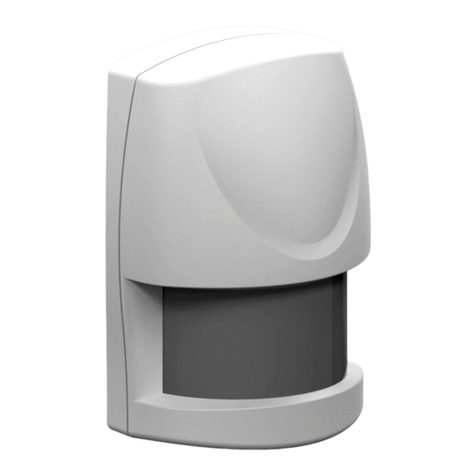
STIF VIGIBELT TOUCH User manual

INSTRUCTION MANUAL GB–1/5
www.stifnet.com - DOC NO. BE0455061-A
USE
- The VIGIBELT®TOUCH is a lateral displacement detector that prevents the offset of elevator straps or conveyor
belts, and or incidentally the elevator pulley offset. It reacts to the pressure of the strap or strip, which comes into
contact with the front face of the detector. The detectors are normally installed face to face in pairs preferably on the
rising leg near the pulleys for the lifts, and on the stretched strand side near the drums for the conveyors.
The detectors can be directly connected to a programmable logic controller, or for total safety to an independent
central unit "monitoring M-JET". The electrical circuit can thus control an alarm or a machine stop.
For elevators taller than 20 meters, we advise to equip the head with a second kit VIGIBELT®always on the rising
sheath side.
The sensors are triggered when the strap exerts a load of about 5 daN.
description
- The VIGIBELT®TOUCH kit is composed of two detectors, four elastomeric wedges of 3mm (NBR), and the fixing
screws (M6).
Composition:
PRECAUTIONS
The VIGIBELT®TOUCH kit must be installed, connected and put into service only by competent personnel. The
personnel need to have electrical accreditation, a knowledge of the regulation and the disposition concerning
the installation of those device, especially for Ex II3D version integrated in ATEX zones.
- Carry out beforehand an electrical connection study to install the VIGIBELT® TOUCH (standardized electrical
diagram, power supply and electrical protection, plc control, ATEX zones).
- Check that the temperature range of use of the VIGIBELT®TOUCH (variable according to version) corresponding
at application.
- Check during the first commissioning of the bucket elevator in the handling phase, that there is no sealing defect
(dust leak) between the sheath of the elevator and the VIGIBELT®TOUCH.
- Shut down the bucket elevator or belt conveyor to a standstill (off) before any installation or intervention on the
VIGIBELT®TOUCH (intervention information to be indicated on the machine).
Z.A. de la lande - 49170 Saint-Georges-sur-Loire - France
Head office, purchasing and factory: tel.: +33 2 41 72 16 80 - Fax +33 2 41 72 16 85
France Export Commercial Service: tel.: +33 2 41 72 16 82 - Fax +33 2 41 39 32 12
email: sales@stifnet.com - Website: www.stifnet.com
SAS with a capital of € 800,000 - R.C.S. Angers B 328 876 503 - 84B12 APE 2511Z - VAT number FR 35 328 876 503
2x VIGIBELT®Touch
8x Fastening Bolts(M6)
4x elastomeric wedges (ep.3)

INSTRUCTION MANUAL GB–2/5
www.stifnet.com - DOC NO. BE0455061-A
installation
1) Make two symmetrical round openings (opening Ø56mm + 4 holes Ø7 on Ø72) on each side on the riser of the
elevator: figure-A
Figure A
On a bucket lift, position the VIGIBELT®TOUCH
detectors on the rising leg side close to the axis of the
pulleys and the strap.
On a belt conveyor, position the VIGIBELT®
TOUCH detectors side stretched strand close to the
axis of the drums and the strip.
Make an opening of
Ø56 in the axis of the
strap
strap

INSTRUCTION MANUAL GB–3/5
www.stifnet.com - DOC NO. BE0455061-A
2) Assemble the M6 pan screws with the low nuts on the sheath (clamping torque 6 N.m): figure-B.
3) Adjust the trigger distance of the VIGIBELT®TOUCH detectors. This distance corresponds to the dimension
between the inner wall of the elevator and the contact face of the detector.
For this, you have the possibility to make three figure-C detection settings:
No. 1 - Detector without additional wedge, thickness elevator (example 3mm), i.e. a distance of 20mm
No. 2 - Detector with an additional wedge, thickness elevator (example 3mm), i.e. a distance of 17mm
No. 3 - Detector with two additional wedges, thickness elevator (example 3mm), i.e. a distance of 14mm
Figure B
Inner face of the sheath
Assembly of pa-head screws + low nuts
Figure C
20mm
17mm
14mm
Setting N°1
Distance of 20mm,
No additional hold
Setting N°3
Distance of 14mm,
With two additional wedges
Setting N°2
Distance of 17mm,
With an additional wedge

INSTRUCTION MANUAL GB–4/5
www.stifnet.com - DOC NO. BE0455061-A
4) Position the VIGIBELT® TOUCH detectors on the openings and screw the M6 brake nuts with the washers
(clamping torque 4 N.m) according to Figure-D.
5) Connect the VIGIBELT®TOUCH according to the electrical scheme E or F:
NC detector = positive safety, permanent control of the proper functioning of the sensor
Signal loss indicates that there is a strap offset problem
Electrical wire cut off
3-wire/NC connection scheme E
colours
BN = Brown
BU = Blue
BK = Black
PVC cable 3x0.11mm² 2m for ATEX zone and non-
ATEX
3-wire connection scheme F
Colours
1 = Black
2 = Grey
4 = Blue
PVC cable 2m for non ATEX 3x0.25mm²
figure D
Attach the VIGIBELT®Touch with
washers and lock nuts
For low voltage sensor, ATEX or not
- 3-wire cable connection
- L=2m cable
- Voltage 12-24V DC
- Voltage limits, including ripple, 10-36V DC
- Switching power ≤100 mA
- temperature Operating: -25... 70°C (Non-ATEX)
-20... 60°C (ATEX)
- Protection - IP67
Caution: Any connection must be made outside the
ATEX zone
For mechanical sensor, out of ATEX zone
- 3-wire cable connection
- L=2m cable
- Tension 12… 250V AC/DC
- NC : Black wire (1) / Grey wire (2)
- NO : Black wire (1) / Blue wire (4)
- Operating temperature: -20... 105°C
- Protection - IP67
Caution: Any connection must be made outside the
ATEX zone

INSTRUCTION MANUAL GB–5/5
www.stifnet.com - DOC NO. BE0455061-A
6) After completing the mechanical and electrical installation of the VIGIBELT®TOUCH, you must proceed to the
verification of each detector to ensure that they are all operational. For this, you need to trigger each VIGIBELT®
TOUCH by pressing their contact face. This simulation makes it possible to validate that the fault information is
communicated to the control system (M-JET monitoring, control plc, ...).
CONTROL & PERIODIC MAINTENANCE
1) To ensure the functional integrity of VIGIBELT®TOUCH, you must schedule periodic inspections. The frequency
of inspections must be sufficient to avoid dangerous situations (situations that affect the intrinsic functioning of the
VIGIBELT®TOUCH).
2) During these inspections, check that the VIGIBELT®TOUCH are not affected by the following defects: dust layer
>2mm, dust leak between the sheath of the elevator and the VIGIBELT®TOUCH, non-operational power supply
voltage, degraded electrical wiring, shocks on the envelope of the VIGIBELT®TOUCH, triggering of the detector with
a charge > 5 daN, etc...
3) In the case of one or more defects found, you must proceed with the restoration in order to correct the defect(s)
before you can use the bucket lift or belt conveyor again.
4) Only personnel trained and authorized in maintenance procedures for these equipment are able to carry out
inspections for VIGIBELT®TOUCH.
DISPOSAL
When dismantling the VIGIBELT®TOUCH, the user must ensure the proper disposal of this device and hand over
to the specialized harvesting centers the components according to their nature (stainless steel, electrical
equipment, seal, etc.).
In the event that the VIGIBELT®TOUCH kit is used, controlled, under conditions contrary to the precautions
described in this instruction manual, STIF declines all responsibility for damage caused to man, animal,
environment, material property.
Table of contents
Popular Security Sensor manuals by other brands
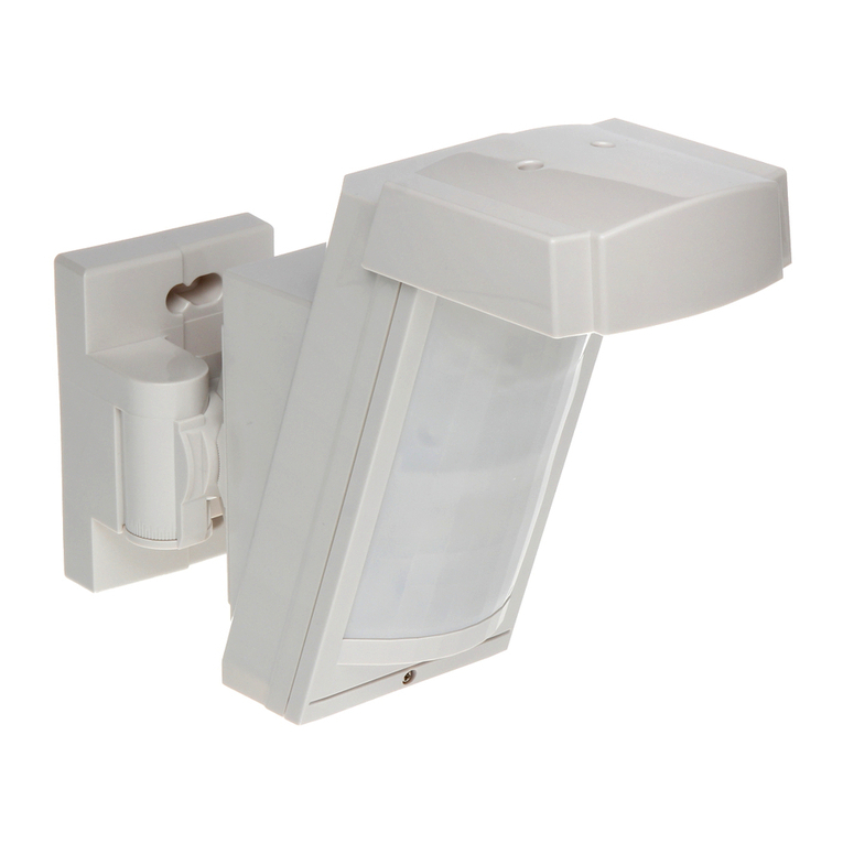
jablotron
jablotron JA-158P quick start guide
Bosch
Bosch DS308EA installation guide

Metasys
Metasys 5451 manual

Hitachi
Hitachi SOR-NEC Installation and operation manual
Niko
Niko Swiss Garde 360 DALI Secondary A-Comfort high ceiling... installation instructions

LOXONE
LOXONE Motion Sensor Air Series quick start guide
