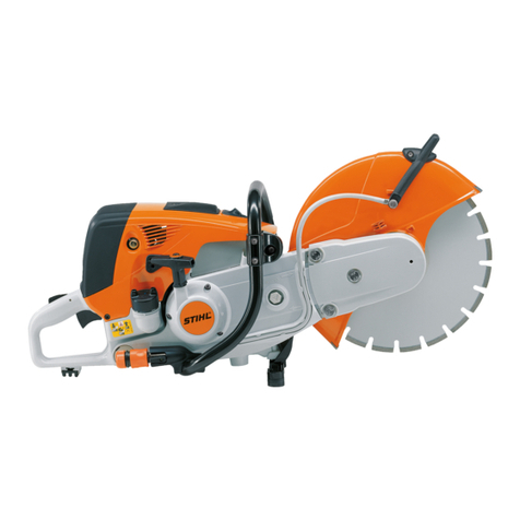
Stihl TS 400 Cutquick User manual

STIHL TS 400 1
6. Ignition system 28
6.1 Spark plug terminal 28
6.2 Ignition lead 29
6.3 Ignition module 30
6.3.1 Ignition timing 30
6.3.2 Removal and
installation 30
6.4 Stop switch lead /
ground lead 31
6.5 Flywheel 32
7. Starter 34
7.1 General 34
7.2 Rewind spring 34
7.2.1 Replacement 34
7.2.2 Tensioning 35
7.3 Starter wheel 35
8. AV handle system 36
9. Throttle control 37
9.1 Throttle trigger interlock,
throttle trigger 37
9.2 Leaf spring 38
9.3 Rod 38
9.4 Handle 38
9.5 Handle mount 39
10. Fuel system 39
10.1 Air filter 39
10.2 Carburetor 41
10.2.1 Leakage testing 41
10.2.2 Removal and
installation 41
10.3 Carburetor adjustment 43
10.4 Tank vent 44
10.5 Pick-up body 45
10.6 Fuel hose 45
10.7 Impulse hose 46
10.8 Manifold 47
10.9 Tank housing 47
11. Special tools and
service accessories 50
11.1 Special tools 50
11.2 Service accessories 52
TABLE OF CONTENTS
1. Introduction 2
2. Specifications 3
2.1 Engine 3
2.2 Fuel system 3
2.3 Ignition system 4
2.4 Cutting wheels 4
2.5 Special accessories 4
2.5.1 For the user 4
2.5.2 For service engineers 4
2.6 Tightening torques 5
3. Cutting wheel drive 6
3.1 Bearing with guard 6
3.2 Checking axial and
radial runout 9
3.3 V-belt 11
3.4 V-belt pulley /
clutch drum 11
3.5 Clamp 12
4. Clutch 13
4.1 Removal and
installation 13
5. Engine 13
5.1 Muffler 13
5.2 Leakage testing 14
5.2.1 Preparatory steps 14
5.2.2 Testing with excess
pressure 15
5.2.3 Testing with negative
pressure 16
5.4 Rotary shaft seals 17
5.5 Exposing the cylinder 18
5.6 Cylinder and piston 19
5.6.1 Removal 19
5.6.2 Installation 20
5.7 Piston rings 22
5.8 Decompression valve 22
5.9 Crankcase 23
5.9.1 Removing the
crankshaft 23
5.9.2 Installing the
crankshaft 25
STIHl
© 1995, Andreas Stihl, Waiblingen

STIHL TS 400 2
1. INTRODUCTION
This Repair Manual contains a
detailed description of all the typical
repair work required for this series of
cut-off machines. Repairs to be
undertaken on standard parts and
assemblies which are used in several
STIHL power tool series are described
in separate repair manuals. Attention
is drawn to these instructions at the
relevant points in this Manual.
The illustrated spare parts lists should
also be consulted when carrying out
repairs, for they show the installed
position and sequence of assembly
for the individual parts.
The latest edition of the respective
parts lists should always be used
when determining the part numbers of
the required replacement parts.
Microfilms are more up-to-date than
printed replacement parts lists!
Faults in the cut-off machine may be
due to several causes. Note the
"Summary of faults" in the manual
"Troubleshooting, standard repairs"
for all function groups.
Note the "Technical Information"
sheets, for they describe technical
changes implemented after publication
of this Repair Manual. The Technical
Information sheets supplement the
replacement parts list until a new
edition is published.
The special tools mentioned in the text
are listed in the last chapter of this
Manual. The tools can also be
identified in the manual of "STIHL
tools" on the basis of this part number.
The manual lists all tools available
from STIHL.
Repairs can be carried out more easily
by mounting the cut-off machine on an
assembly stand (1). It is attached to
the cast arm with two hex bolts (2)
M8x25 after removing the bearing with
guard.
The cut-off machine can then be
swivelled into the most suitable
working position, leaving both
hands free for the work itself.
Repair Manuals and Technical
Information sheets should always be
on hand wherever repairs are carried
out. They must not be passed on to
third parties.
The following graphic symbols are
used in the text and illustrations in
order to make this Manual easier to
use and understand:
In the text:
• = Activity to be carried out;
corresponds to the activity in the
picture above the text.
- = Activity to be carried out, but is not
shown in the picture above the text.
In the illustrations:
= Arrow indicating: Note
= Arrow indicating: Go to
Always use original STIHL
replacement parts. Original STIHL
parts can be identified by the STIHL
part number, the
STIHl
logo
and the STIHL parts symbol (.
The symbol may appear alone on
small parts.
STIHL TS 400 3
2. SPECIFICATIONS
2.1 En
g
ine STIHL single-cylinder two-stroke engine with specially
impregnated cylinder bore
2.2 Fuel system
Displacement:
Cylinder bore:
Piston stroke:
Compression:
Power output to DIN 70020:
Max. torque:
Max. spindle speed:
Mean idle speed:
Crankshaft bearings:
Big-end bearing:
Small-end bearing:
Piston pin:
Connecting rod length:
Starter system:
Reserve pull in rope rotor:
Starter rope:
Clutch:
Diameter:
Clutch engages at:
Leakage testing of the
crankcase
with excess pressure:
with negative pressure:
Carburetor:
Setting
High-speed adjusting screw H:
Low-speed adjusting screw L:
Leakage testing of the
carburetor with excess pressure:
Fuel tank capacity:
Octane rating:
Fuel mix:
Mixing ratio:
Air filter:
64.1 cm3
49 mm
34 mm
9.5 :1
3.2 kW (4.4 HP)
4.1 Nm
at n = 6500 rpm
4800 rpm
2500 rpm
Two ball bearings
Needle cage
Needle cage
Dia. 10 mm
58 mm
Pawl engagement
At least 1/2 turn
Dia. 3.5 mm
Centrifugal clutch without linings
75 mm
3500 rpm
pü= 0.5 bar
pu= 0.5 bar
Diaphragm carburetor
Approx. 1 turn open
Approx. 1 turn open
(standard setting)
pü= 0.8 bar
0.74 1(740 ccm)
At least 90 ROZ
Brandname regular-grade petrol
Brandname two-stroke engine oil
1:50
for STIHL two-stroke engine oil 1:50
1:25
for all other brandname two-stroke
engine oils
Prefilter (foam)
Main filter (paper filter)
and flocked auxiliary filter

STIHL TS 400 4
Principle:
Air gap:
Ignition timing:
Spark plug (suppressed):
Electrode gap:
Spark plug thread:
Thread length:
Heat range:
Length of ignition lead
Cutting wheel for stone
Cutting wheel for steel
Cutting wheel for stone
Cutting wheel for asphalt
Cutting wheel for stone
Cutting wheel for steel
Cutting wheel for stone
Diamond cutting wheel for asphalt
Cutting depth
STIHL cart
Cart attachment kit
Cutting depth limiter
Water tank attachment
Water attachment for wet cutting
V-belt guard kit
Bearing with guard D 300
Set of gaskets
Set of carburetor parts
Sealing panel
Transistor-controlled
(non-contacting) magneto ignition
with integrated controller and
electronic speed limitation
0.15...0.3 mm
1.6...2.2 mm before UDC
at n = 8000 rpm
Bosch WSR 6F or
NGK BPMR 7 A
0.5 mm
M 14x1.25
9.5 mm
200
370 mm
Dia. 300x3.5x20 mm
Dia. 300x3.5x20 mm
Dia. 300x6.0x20 mm
Dia. 300x3.5x20 mm
Dia. 350x4.0x20 mm
Dia. 350x4.0x20 mm
Dia. 300x2.6x20 mm
Dia. 300x3.2x20 mm
Approx. 100 mm (for dia. 300 mm)
Approx. 125 mm (for dia. 350 mm)
2.3 I
g
nition s
y
stem
2.4 Cuttin
g
wheels
2.5.2 For service enginee
r
2.5.1 For the use
r
2.5 Special accessories

STIHL TS 400 5
DG screws are screwed into plastic and light metal parts. These screws cut a thread in the material when they are screwed
in for the first time. The material is permanently deformed. The screws can then be removed at will and retightened without
impairing the strength of the screw connection, provided that the specified tightening torque is maintained. It is therefore
essential to use a torque wrench.
2.6 Ti
g
htenin
g
torques
Size of
thread
IS-DG 4x14
IS-DG 4x15
IS-DG 4x15
IS-DG 5x20
IS-DG 5x20
M5
IS-M 5x16
IS-M 5x16
IS-M 5x16
IS-M 5x16
IS-M 5x16
IS-M 5x20
IS-M 5x20
IS-M 5x20
IS-M 5x20
IS-M 5x20
IS-M 5x20
IS-M 5x20
IS-M 5x20
IS-M 5x20
IS-M 5x25
IS-M 6x16
IS-M 6x16
IS-M 6x16
M 5x55
M 8x1
M 8x1
M 12x1 L
M 14x1.25
M 10x.. L
Connecting
element
Groove-headed screw
Socket-head screw
Socket-head screw
Socket-head screw
Socket-head screw
Nut
Socket-head screw
Socket-head screw
Socket-head screw
Socket-head screw
Socket-head screw
Socket-head screw
Socket-head screw
Socket-head screw
Socket-head screw
Socket-head screw
Socket-head screw
Socket-head screw
Socket-head screw
Socket-head screw
Socket-head screw
Socket-head screw
Socket-head screw
Socket-head screw
Grub screw
Nut
Nut
Driver
Nut
For component Tightening torque
(Nm)
Starter cover 1.8
Handle moulding / handle 1.8
Retainer, stop rods 1.8
Handle / handle mount 8.0
Tank housing left / right 7.5
Filter base / carburetor 3.5
Cover, clamp / cast arm 4.5
Handle / tank housing 8.0
Air guide cover / crankcase 4.5
Muffler / crankcase 10.0
Muffler / cylinder 10.0
Cast arm / crankcase 10.0
Filter base / crankcase 6.0
Filter housing / filter base 4.0
Shroud / tank housing 6.0
Crankcase left / right 10.0
Fan cover / tank housing 6.0
Starter cover / cast arm 6.0
Cylinder / crankcase 10.0
Ignition module / crankcase 8.0
Support / handle / tank housing 8.0
AV element, cast arm / handle 6.0
AV element, tank housing / cast arm 6.0
AV element, tank housing / crankcase, left 6.0
Tank housing / carburetor 4.0
Flywheel 30.0
Starter wheel 23.0
Clutch 40.0
Spark plug 27.5
V-belt pulley / bearing 37.5
Decompression valve 14.0
Remark
1)
2)
When screwing the DG screws into an existing screw thread:
- Insert the DG screw in the hole and turn counterclockwise until it gently drops into the hole in axial direction.
- Turn the screw clockwise and tighten with the specified torque.
This procedure guarantees that the screw engages in the existing screw thread without cutting a new thread and thus
prevents the strength of the screw connection being weakened.
1) Secure screw with adhesive 0786 111 1109 (Loctite 270).
2) A washer must be fitted under the head of the screw.
Note: Screws secured with adhesive must be heated with a hot-air fan (drier) in order to release them.
Great care must be exercised with plastic parts!

STIHL TS 400 6
3. CUTTING WHEEL DRIVE
3.1 Bearing with guard
Check axial and radial runout, see
chapter 3.2.
• Relax V-belt; turn hexagon on clamp
counterclockwise until the arrow
points to the left (to "0").
• Unscrew the screw (1) in the
thrust washer (2).
- Remove thrust washer.
• Remove woodruff key (1) from
groove in shaft.
• Remove washer (2) from shaft.
• Unscrew bearing screws (1).
• Remove guard (2).
• Remove axial clamping ring from
shaft.
• Remove thrust washer (1).
• Draw shaft out of deep groove ball
bearings.
• Lever bearing with guard out of
V-belt. • Lock V-belt pulley in position.
• Unscrew nut and draw V-belt
pulley off shaft.
Important! Nut has left-hand
thread.

STIHL TS 400 7
Important! Use pliers with
shortened, rounded tips.
Note: Particular attention must be paid
to the following points.
• Insert circlip in one of the
grooves of the bearing.
• Remove flange. • Remove washer and rubber ring. • Press both deep groove ball
bearings and the ring out of the
bearing with drift pin (1).
The parts are reassembled in
reverse order.
• Draw bearing out of rubber ring.
• Unscrew both screws (1) and
remove with helical springs (2) and
sleeves.
• Remove circlips from the
grooves in front of the deep
groove ball bearings.
• Remove washer with rubber ring.

STIHL TS 400 8
• Slide first deep groove ball bearing (1),
ring (2) and second deep groove ball
bearing (3) onto the shaft.
• Place washer on bearing.
- Place bearing in rubber bearing from
the outside.
• Slide on V-belt pulley with the longer,
machined-down collar first and secure
nut with 37.5 Nm.
• Position the deep groove ball bearing
and press in with shaft until it rests
against circlip.
- Draw shaft out of deep groove ball
bearings.
- Insert second circlip in groove of
bearing.
Important! The seal of the ball bearing
must not be damaged.
• Place washer on flange.
- Insert flange from the inside.
• Fit thrust washer so that the groove is
located over the nose.
- Insert axial clamping ring.
• Slide sleeve (1) and spring (2) onto
screw (3).
- Turn in and tighten screws.

STIHL TS 400 9
3.2 Checking axial and
radial runout
Since changes in the shaft diameter
(due to scoring, etc.) affect the radial
runout of the cutting wheel, it is
sufficient carefully to inspect the
shaft around the cutting wheel
mount.
The axial runout, on the other hand,
depends on the condition of several
components and should therefore be
determined by measurement.
- Unscrew the screw and remove the
thrust washer.
- Insert V-belt in V-belt pulley of
bearing, fit guard and loosely
screw in the fastening screws.
• Turn hexagon of clamp clockwise.
• The clamp comes within range of the
spring force after approx. 1/8 of a turn.
It must be then be turned to the limit
(approx. 1/8 of a turn).
Note: The wrench must not be
forcibly turned further.
- Tighten all three fastening screws,
starting with the screw at the rear.
-Turn in and tighten the screw.
•Secure the gauge holder (1) with
gauge (2) on the shroud so that the
axial runout can be determined for a
diameter of approx. 130 mm over a
full revolution of the wheel. Refer to
the test sequence table.
- Dismantle the test equipment
after testing.
• Fit the thrust washer so that the
catches (1) engage in the locking
grooves (2) of the shaft.
• Fit a test washer (1).

STIHL TS 400 10
Test sequence
Radial runout:
Visual inspection,
spindle (shaft)
Axial runout:
Axial runout tested with
STIHL test wheel or
diamond cutting wheel
(on 130 mm dia.)
Actual condition
Wear marks or scoring
around the cutting wheel
mount
Axial runout
≤0.15 mm
> 0.15 mm
Mating faces of the thrust
washers damaged or uneven
(particularly in the case of the
inner thrust washer), mating
faces not level, parts are not
original STIHL parts
Spindle (shaft)
damaged
Tangible radial play in the
bearing seat →
spindle bearing defective
Possible causes
Fastening screw loose during
operation, wrong cutting
wheels used (mount dia. > 20
mm or > 22 mm)
Dirt, thrust washers or
cutting wheel fitted
incorrectly, use of force
during cutting or
transport
Incorrect handling,
use of force
Deep groove ball bearing
damaged by dirt and/or
seat of spindle bearing worn
Remedy
Replace spindle
(shaft)
None
Replace thrust
washers
Replace spindle
(shaft)
Replace spindle
and deep groove
ball bearing

STIHL TS 400 11
3.4
V
-belt pulley /
clutch drum
3.3
V
-belt
• Draw ring off crankshaft stub.
The parts are reassembled in
reverse order.
• Check clutch drum; it must not be
scored or severely worn, otherwise
the V-belt pulley must be replaced.
• Remove starter cover.
• Remove V-belt from V-belt pulley.
The parts are reassembled in
reverse order.
Note: The screws of the starter
cover must be tightened with a
torque of 6 Nm.
• Remove circli
p
.Note: The ball bearing must be
pressed in as far as possible with
drift pin (1).
- Remove bearing with guard, see
chapter 3.1.
• Unscrew the screws of the
starter cover.
- Remove V-belt, see chapter 3.3.
- Remove starter wheel, see
chapter 7.3.
• Draw V-belt pulley off crankshaft
stub.
• Force out ball bearing with drift
pin (1).

STIHL TS 400 12
3.5 Clamp
•
- Remove starter cover,
see chapter 3.3.
• Turn hexagon on clamp clockwise
until the internal helical spring is
completely detensioned.
• Remove the clamping lever from the
housing slot.
The parts are installed in reverse
order.
Insert both parts together. Tighten
the fastening nuts with a torque of
4.5 Nm.
• Remove the clamp. Insert the hook of the draw bar
into the bore.
• Unscrew the fastening screws of
the clamp. Note: The clamp must be
assembled if necessary.

STIHL TS 400 13
5. ENGINE
5.1 Muffler
Refer to the manual
"Troubleshooting, standard
repairs" for troubleshooting
procedures.
Note: The spark arresting screen
can also be replaced without
removing the muffler.
- Remove bearing with guard,
see chapter 3.1.
4. CLUTCH
4.1 Removal and installation
Refer to the manual "Troubleshootings,
standard repairs" for troubleshooting
procedures.
- Remove V-belt, see chapter 3.4.
• Unscrew clutch and attachment
from the crankshaft.
Important! The clutch has a
left-hand thread.
- Remove the cover washer from
the crankshaft stub.
- Dismantle and reassemble
clutch; see manual "Trouble-
shooting, standard repairs".
• Screw on clutch and tighten to
40 Nm with insert (1).
- Attach V-belt pulley,
see chapter 3.4.
• Unscrew the muffler screws.
• Remove muffler.
• Slip on cover washer with the
word "TOP" pointing outwards.

STIHL TS 400 14
5.2 Leakage testing
Defective rotary shaft seals and
gaskets or cracks in the castings
cause leaks through which
supplementary air can enter and
change the composition of the
fuel/air mixture taken in.
Above all, this makes it very much
more difficult, if not impossible, to
set the correct idle speed.
In addition, it also prevents a
faultless transition from idle to full
or part-load operation.
The crankcase can be tested to
ensure it is absolutely tight with the
aid of the carburetor / crankcase
tester and the vacuum pump.
5.2.1 Preparator
y
steps
• Draw out the spark arresting
screen.
- Clean the spark arresting
screen; fit new screen if
necessary.
- Remove shroud, see chapter 5.5.
• Unscrew the muffler screws
half-way.
- Remove gasket.
Note: When fitting muffler, position
new gasket so that the bead (1)
points towards the muffler.
• Slide a sealing plate (1) between
muffler and cylinder exhaust port
and tighten both the upper screws.
Note: The sealing plate must fill the
full width between the screws.
- Remove carburetor,
see chapter 10.3.
- Set piston to upper dead center
(UDC) (can be seen through the
inlet port).
• Compress and remove the clip.

STIHL TS 400 15
5.2.2 Testing with
excess pressure
• Connect the pressure hose of
the tester to the nipple on the
test flange.
- Check that the spark plug is
secure.
• Pump air into the crankcase with
the aid of the rubber bulb until an
excess pressure of 0.5 bar is
indicated on the pressure gauge.
There are no leaks in the crank-
case if this pressure is maintained
for at least 20 seconds.
• Install test flange (1) instead of
the carburetor.
Important! The pin must be
inserted in the impulse hose (2)
correctly when installing the test
flange.
• Remove decompression valve.• Check that the sleeve is present in
the manifold.
• Check whether pin (1) is located in
bore No. 1 in the test flange and
screw it in if necessary.
• Screw in and tighten plug (1)
instead of the decompression
valve.
• Close venting screw (1) on the
rubber bulb.

STIHL TS 400 16
5.2.3 Testing with
negative pressure
The rotary shaft seals usually fail in
the presence of a negative pressure.
Due to the absence of an inner
counterpressure, the sealing lip lifts
off the crankshaft during the piston's
induction stroke.
This defect can be identified by
additional testing with a vacuum
pump. The preparatory steps for
this test are the same as when
testing with excess pressure as
described in chapter 5.2.1.
• Close venting screw (1) on the
pump piston.
• Actuate lever (2) until a vacuum
of 0.5 bar is indicated on the
pressure gauge.
Note: The rotary shaft seals are in
perfect working order if the indicated
negative pressure is maintained or if
the pressure does not rise above
0.4 bar within 20 seconds. If the
pressure continues to increase
(elimination of negative pressure in
crankcase), however, the rotary shaft
seals must be replaced even if the
vacuum test did not reveal any leaks.
- Reopen venting screw and
remove hose after testing.
- Remove test flange and install
carburetor as described in
chapter 10.2.2.
- Unscrew muffler screws.
- Draw out sealing plate.
- Tighten muffler screws with a
torque of 10.0 Nm.
- Fit shroud, see chapter 5.5.
• Connect the intake hose of the
vacuum pump to the nipple of
the test flange.
- Check that the spark plug is
secure.
- The leak must be located and the
defective part replaced if the
pressure drops.
Note: Coat the supposedly
defective area with oil and
pressurize the crankcase again.
Bubbles form in the oil-coated
area if defective.
- Then test under vacuum as
described in chapter 5.2.3.
- After testing, open venting screw
and remove hose.
- Remove test flange and install
carburetor, see chapter 10.2.2.
- Unscrew muffler screws.
- Draw out sealing plate.
- Tighten muffler screws with a
torque of 10.0 Nm.
- Fit shroud, see chapter 5.5.

STIHL TS 400 17
• Position extractor (1) (jaws with
No. 1 profile).
- Tension arms.
- Draw out rotary shaft seal.
Important! The crankshaft stub
must not be damaged.
- Clean the sealing face with a
conventional solvent-based
degreasing agent without CFCs
and halogenated hydrocarbons as
described in chapter 11.2.
- Coat the sealing lips of the rotary
shaft seal with grease,
see chapter 11.2.
- Slide the rotary shaft seal over the
assembly sleeve with the open side
facing the crankcase.
• Press it into place with press
sleeve (1).
- Remove assembly sleeve.
- Install clutch, see chapter 4.1.
• Fit extractor (1).
- Tension arms.
- Draw out rotary shaft seal.
Important! The crankshaft stub must
not be damaged.
- Clean the sealing face with a
conventional solvent-based
degreasing agent without CFCs and
halogenated hydrocarbons as
described in chapter 11.2.
- Coat the sealing lips of the rotary
shaft seal with grease,
see chapter 11.2.
5.4 Rotary shaft seals
The engine need not be dismantled
if only the rotary shaft seals are to be
replaced.
Clutch side:
- Remove clutch, see chapter 4.1.
Note: Lightly knock against the rotary
shaft seal with a suitable tube or punch
to drive it out of its seat.
Ignition side:
- Remove flywheel,
see chapter 6.5.
- Install jaws with profile 3.1 on
extractor.
Note: Lightly knock against the
rotary shaft seal with a suitable tube
or punch to drive it out of its seat.
• Slide assembly sleeve (1) over
crankshaft stub.

STIHL TS 400 18
5.5 Exposing the cylinde
r
Check and repair the fuel supply,
carburetor, air filter and ignition
system before locating faults in the
engine.
Refer to the manual "Trouble-
shooting, standard repairs" for
troubleshooting procedures.
- Remove muffler, see chapter 5.1.
• Depress throttle trigger slightly
and draw throttle rod out of
trigger.
• Remove spark plug terminal (1)
from spark plug.
• Remove ignition lead and stop
switch lead from mount (2).
• Set choke lever to upward
position.
- Slide the rotary shaft seal over the
crankshaft stub with the open side
facing the crankcase.
• Press it into place with press
sleeve (1).
- Install flywheel, see chapter 6.5.
• Press cap in at bottom, slide
upwards and remove. • Unscrew shroud screws.
Note: One of the screws is not
shown in the picture.
- Remove shroud.

STIHL TS 400 19
5.6 Cylinder and piston
5.6.1 Removal
The tabs (1) on the cap must
engage in the guides (2) in the
shroud.
Preparatory steps are described in
chapter 5.5.
• Unscrew spark plug.
• Unscrew the screws of the air
guide cover.
- Remove air guide cover.
The parts are reassembled in
reverse order.
Check that spout for decompres-
sion valve is located correctly on
the shroud.
Set the slide control to "I" before
assembling the shroud.
• Unscrew the cylinder base screws
through the holes in the cylinder.
- Draw cylinder off piston.
• Disconnect hose clip (1) of
manifold (2).
- Slide manifold off intake port.
Note: A ground lead must be fitted
between the air guide cover and the
housing.

STIHL TS 400 20
• Lever the hookless snap rings out of
the annular grooves with a drawing
pin or similar implement.
• Check and replace piston rings,
see chapter 5.7. • Insert the assembly pin through
the piston bore and conrod eye
(needle cage) with the stub first
and align the piston.
• Heat piston to approx. 60 °C on a
hotplate and slide onto conrod. The
mark (1) on the piston base must
point away from the manifold (2).
• Remove cylinder gasket.
• Press piston pin (1) out of the
piston with assembly pin (2).
Note: If the piston pin is stuck, it can
be released by lightly knocking
against the assembly pin with a
hammer. The pin must be steadied
in order not to transmit the knocks to
the conrod.
- Remove piston from conrod and
draw needle cage out of the
conrod eye.
• Thoroughly clean sealing face
(1).
• Coat needle cage (2) with oil and
insert in conrod eye.
- Remove decompression valve
as described in chapter 5.8.
- Check cylinder and replace if
necessary.
Note: The corresponding piston must
also be fitted when installing a new
cylinder. New cylinders are therefore
only available with piston.
5.6.2 Installation
Other manuals for TS 400 Cutquick
2
Table of contents
Other Stihl Chainsaw manuals

Stihl
Stihl E 220 User manual

Stihl
Stihl MS 151 TC User manual

Stihl
Stihl MS 441 C User manual

Stihl
Stihl MS 441 C-MQ Magnum User manual

Stihl
Stihl MSA 120 C User manual

Stihl
Stihl MS 151 C User manual

Stihl
Stihl 171 User manual

Stihl
Stihl MS 192 User manual

Stihl
Stihl MSA 160 C User manual

Stihl
Stihl MS 460 User manual