Page 6 Technical Information 19.2010
TI_19_2010_30_01_01.fm
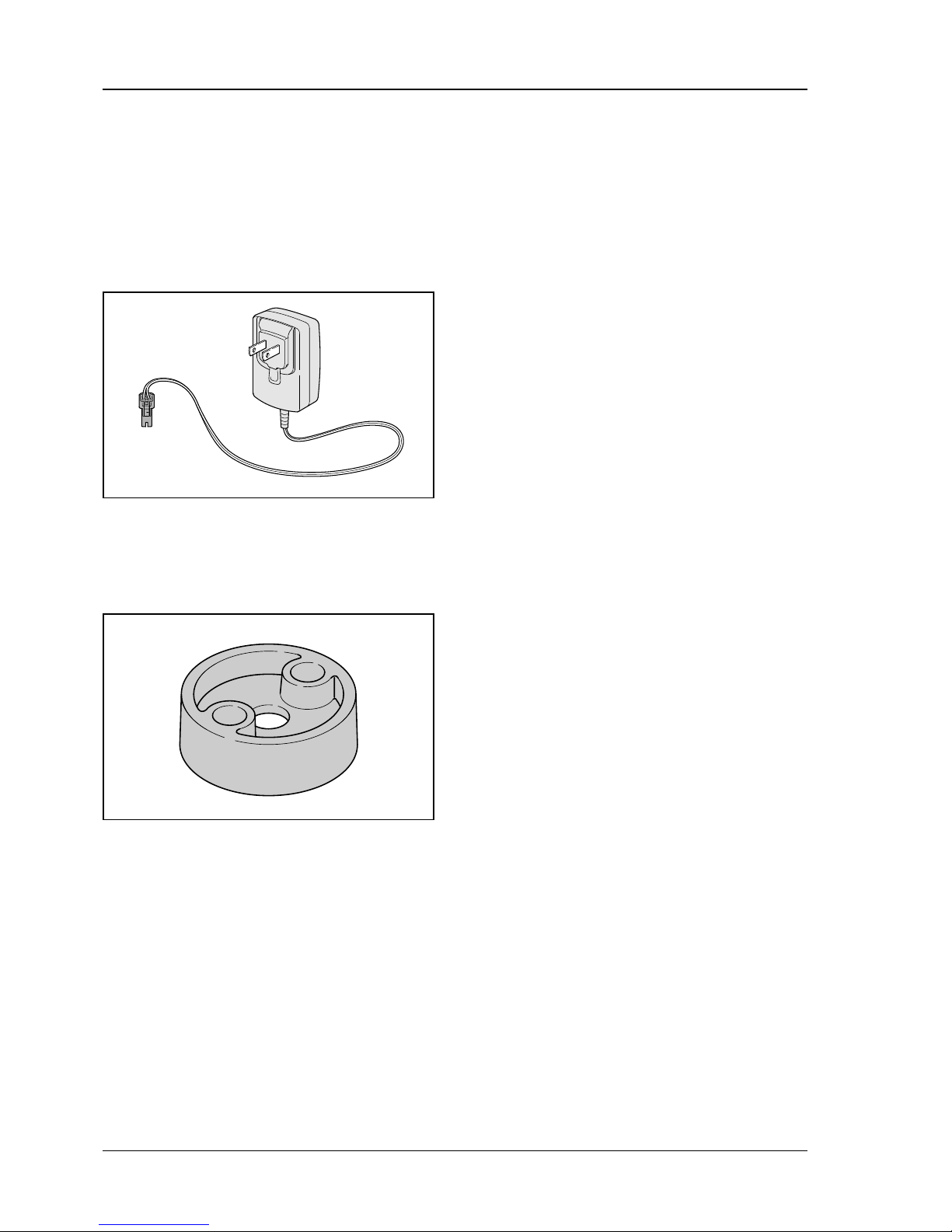
5.2 Connecting the Power Adapter
The power adapter 4238 400 8500 permits fast
troubleshooting. Connect the power adapter to the
generator connection on the solenoid valve and the
power source.
With the power adapter connected, all other
components of the electronic water control (control
panel, short circuit wire, solenoid) must be
connected except the generator. If a component is
replaced, then the power adapter must be
disconnected from the generator connection on the
solenoid valve and then reconnected after the
repair.
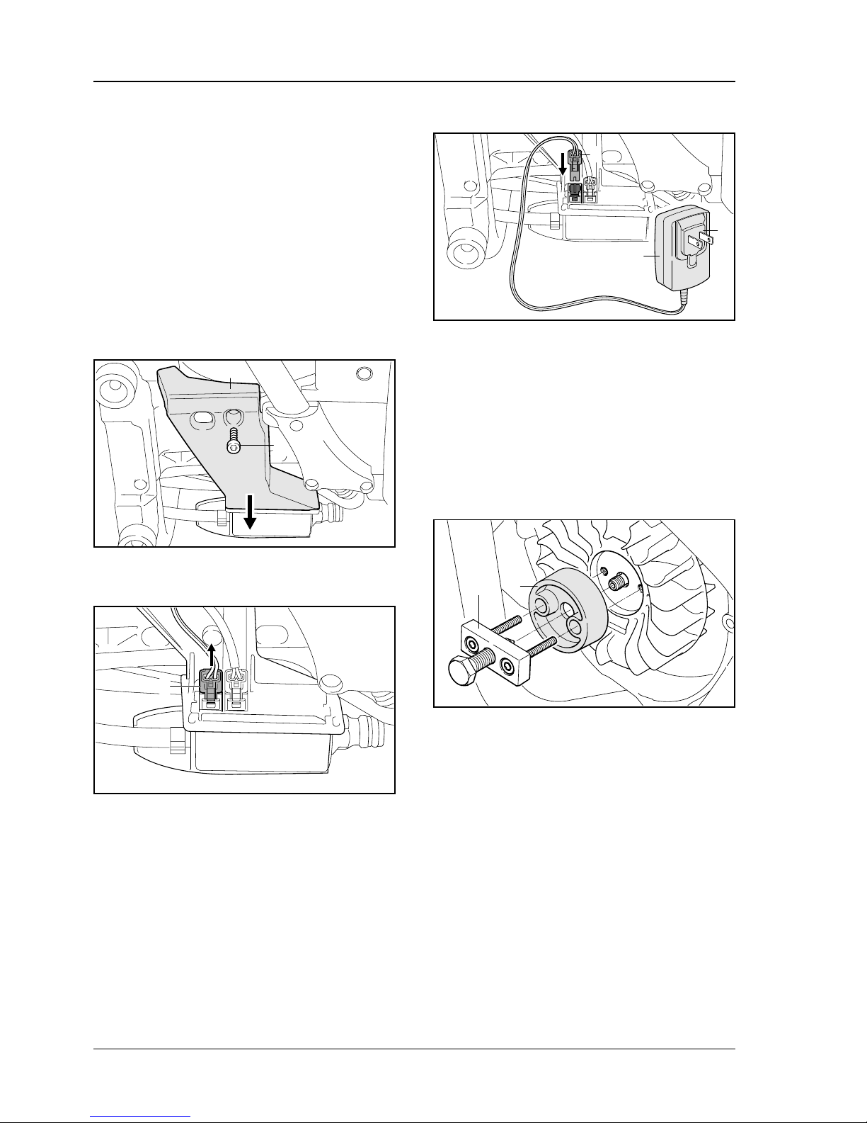
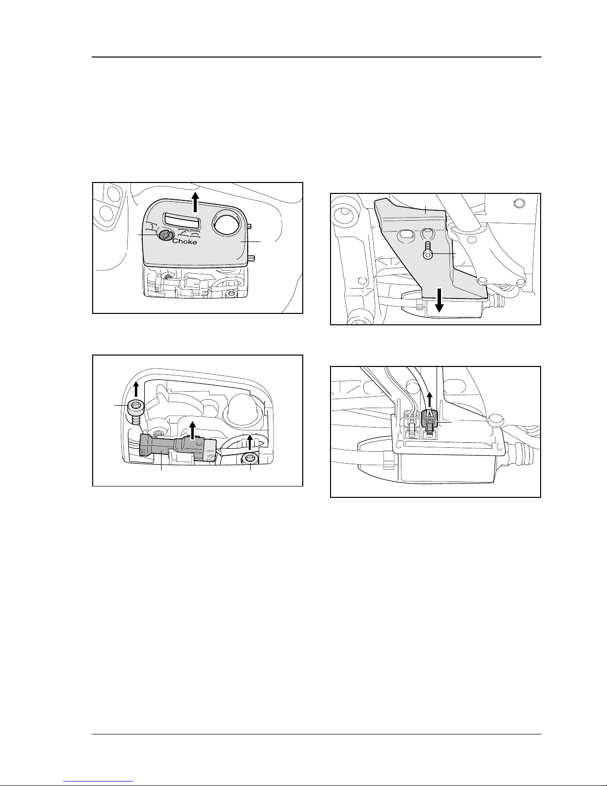
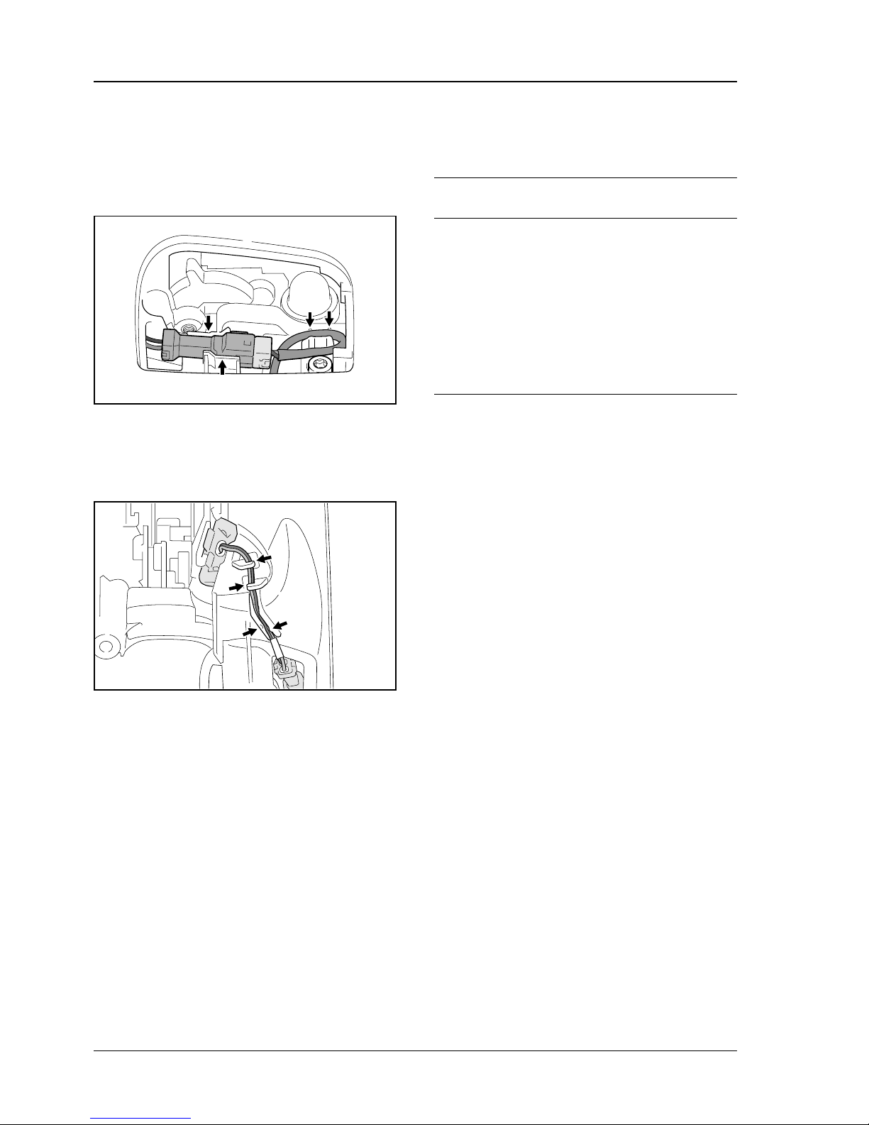
.Unscrew bolt (1)
.Remove cover (2)
.Disconnect the generator plug (3) from the
solenoid valve
.Connect the plug (4) of the power adapter (5) to
the solenoid valve
.Plug power adapter (6) into a properly installed
power outlet – voltage source and operating
voltage of power adapter must match
Once the power adapter is connected, clicking of the
solenoid valve should be heard (see b5.1).
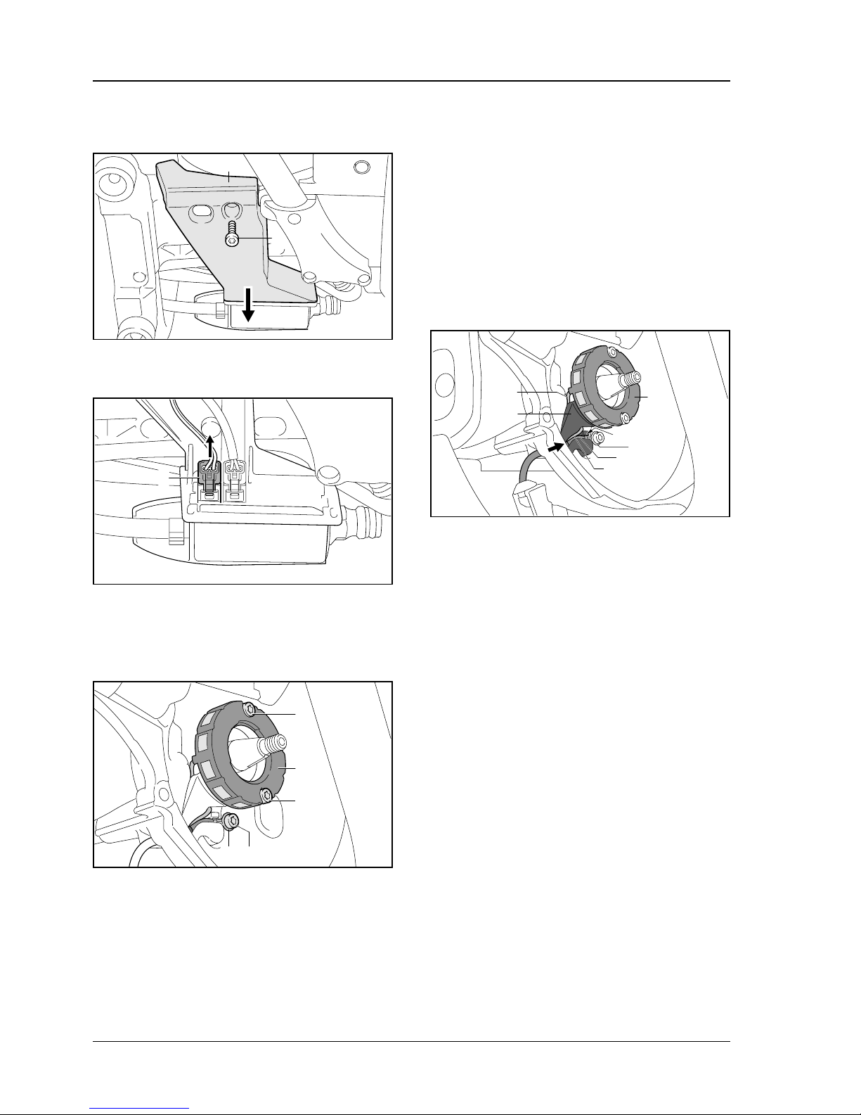
5.3 Removing the Flywheel
With the cut-off machines STIHL Cutquik®
TS 410-A, TS 420-A, the flywheel must be removed
using the previous puller (1) 1135 890 4500 (to be
changed to 5910 890 4504) and the new spacer (2)
4238 894 1100 (see b3.1.2) in order to avoid
damaging the generator beneath it.
STIHL recommends also using the new spacer (2)
4238 894 1100 in combination with the previous
puller (1) 1135 890 4500 (to be changed to
5910 890 4504) for the cut-off machines
STIHL Cutquik®TS 410, 420 without electronic
water control, since this ensures straight positioning
of the puller.
1
370TI058 KN
2
3
370TI059 KN
4
370TI076 KN
5
6
370TI061 KN
1 2