FSA 90 R
English
5
Cutting Attachments
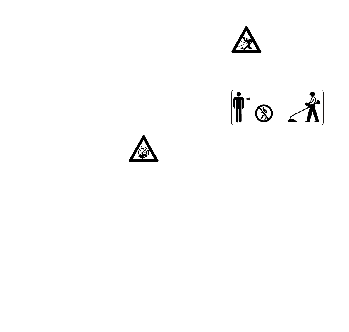
The deflector on this power tool cannot
protect the operator from all objects
thrown by the cutting attachment
(stones, glass, wire, etc.). Such objects
may ricochet and then hit the operator.
Check the cutting attachment at regular
short intervals during operation or
immediately if there is a noticeable
change in cutting behavior:
–Switch off the motor, move the
retaining latch to ƒ and wait for the
cutting attachment to come to a
standstill, remove the battery.
–Check condition and tightness, look
for cracks.
To replace the cutting attachment,
switch off the power tool, move the
retaining latch to ƒ and remove the
battery. This avoids the risk of injury
from the motor starting unintentionally.
Never continue using or attempt to
repair damaged or cracked cutting
attachments.
This may cause parts of the cutting
attachment to come off and hit the
operator or bystanders at high speed
and result in serious or fatal injuries.
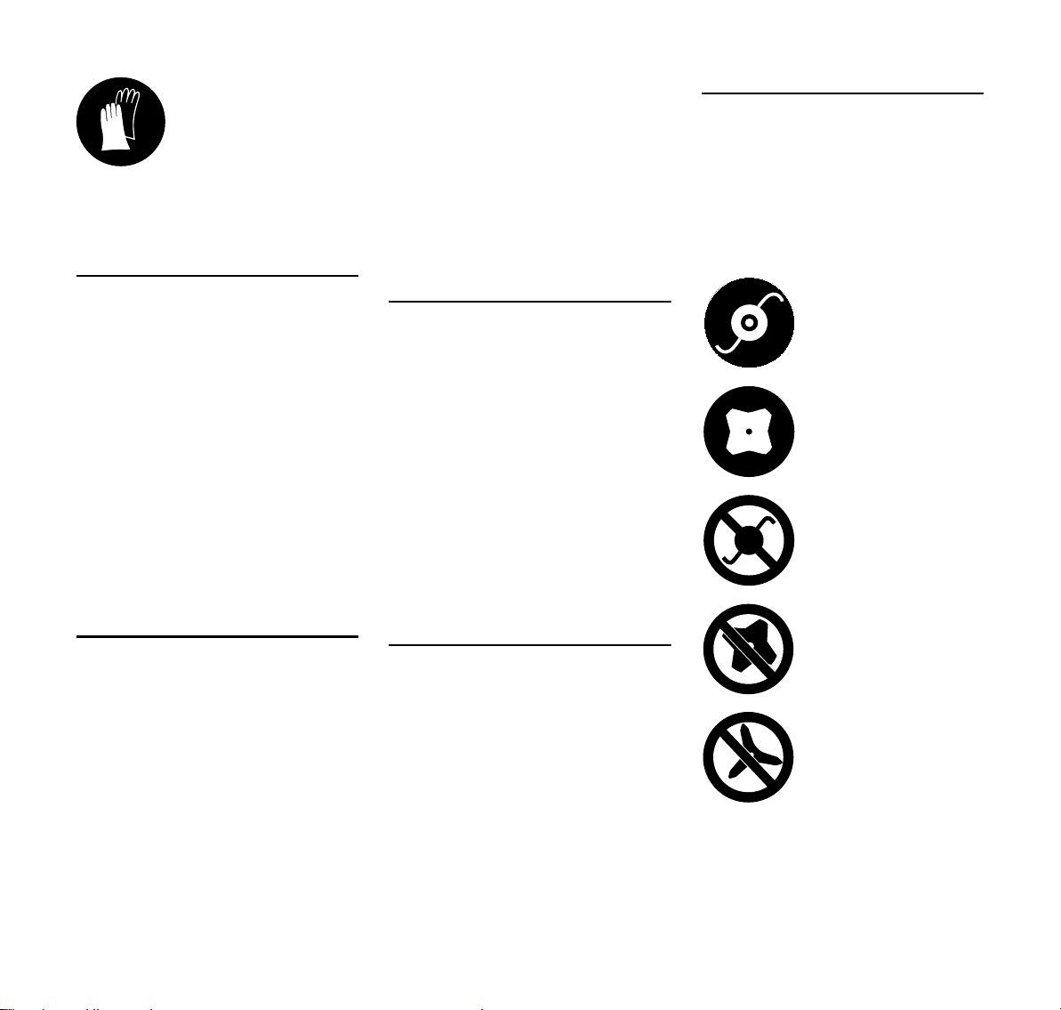
Using Mowing Heads
Use only the deflector with properly
mounted line limiting blade to ensure the
mowing lines are automatically trimmed
to the approved length.
Before adjusting nylon line on manually
adjustable mowing heads, switch off the
machine, set retaining latch to ƒ and
remove the battery. This avoids the risk
of injury from the motor starting
unintentionally.
WARNING
To reduce the risk of serious injury,
never use wire or metal-reinforced line in
place of the nylon line.
Using Metal Cutting Attachments
STIHL recommends the use of original
STIHL metal cutting attachments. They
are specifically designed to match your
model and meet your performance
requirements.
Metal cutting attachments rotate at very
high speed. The forces that occur act on
the machine, the attachment and the
material being cut.
Sharpen metal cutting attachments
regularly as specified.
Check sharpness. Replace or sharpen
dull metal cutting attachments
immediately.
Unevenly sharpened metal cutting
attachments cause out-of-balance
which can impose extremely high loads
on the machine and increase the risk of
breakage.
Dull or improperly sharpened cutting
edges can put a higher load on the metal
cutting attachment and increase the risk
of injury from cracked or broken parts.
Inspect metal cutting attachments for
cracks or warping after every contact
with hard objects (e.g. stones, rocks,
pieces of metal). To reduce the risk of
injury, remove burrs and other visible
build-ups of material (use a file) because
they may become detached and be
thrown at high speed during operation.
Do not continue using or attempt to
repair damaged or cracked metal cutting
attachments by welding, straightening or
modifying the shape (out of balance).
If a rotating metal cutting attachment
makes contact with a rock or other solid
object there is a risk of sparking which
may cause easily combustible material
to catch fire under certain
circumstances. Dry plants and scrub are
also easily combustible, especially in hot
and dry weather conditions. If there is a
risk of fire, do not use metal cutting
attachments near combustible
materials, dry plants or scrub. Always
contact your local forest authority for
information on a possible fire risk.
To reduce the above-mentioned risks
when using a metal cutting attachment,
never use a metal cutting attachment
with a diameter larger than specified. It
must not be too heavy. It must be
manufactured from materials of
adequate quality and its geometry must
be correct (shape, thickness).
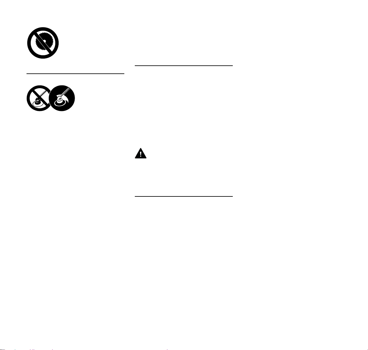
Deflector must not be
used with circular saw
blades.
To reduce the risk
of injury from
thrown objects,
never operate the
power tool without
the proper deflec-
tor for the type of
cutting attachment
being used.