STIL CHR 150 Operating instructions

-~
ARTISAN
®
~I
TECHNOLOGY
GROUP
Your definitive source
for
quality
pre-owned
equipment.
Artisan Technology
Group
Full-service,
independent
repair
center
with
experienced
engineers
and
technicians
on staff.
We
buy
your
excess,
underutilized,
and
idle
equipment
along
with
credit
for
buybacks
and
trade-ins
.
Custom
engineering
so
your
equipment
works
exactly as
you
specify.
•
Critical
and
expedited
services
•
Leasing
/
Rentals/
Demos
• In
stock/
Ready-to-ship
•
!TAR-certified
secure
asset
solutions
Expert
team
ITrust
guarantee
I
100%
satisfaction
All
tr
ademarks,
br
a
nd
names, a
nd
br
a
nd
s a
pp
earing here
in
are
th
e property of
th
e
ir
r
es
pecti
ve
ow
ner
s.
Visit our website - Click HERE

STIL S.A.
595, rue Pierre Berthier – Domaine de Saint Hilaire – 13855 Aix-en-Provence cedex 3, France
Tel: +33 (0)4 42 39 66 51 – Fax : +33 (0)4 42 24 38 05
Email : stil.sa@wanadoo.fr – Web site : www.stilsa.com
CHR 150
Operating and maintenance manual

STIL - CHR 150 – Operating and maintenance manual Doc ref. CHR2-001-P2 Re :D
Page 2 of 49
CONTENTS
1
PRESENTATION OF THE RANGE OF CHR SENSORS...................................................................... 4
2
PRESENTATION OF THE CHR 150......................................................................................................... 4
2.1
C
ONTROLLER
........................................................................................................................................... 4
2.2
O
PTICAL PEN AND OPTICAL FIBER
............................................................................................................. 5
3
SAFETY......................................................................................................................................................... 6
3.1
T
HERMAL
H
AZARDS
................................................................................................................................ 6
3.2
E
LECTRICAL
H
AZARDS
............................................................................................................................. 6
3.3
O
PTICAL
H
AZARDS
................................................................................................................................... 6
3.4
G
ENERAL
R
ECOMMENDATIONS
................................................................................................................ 6
3.5
C
OMPLIANCE TO THE
EC
REGULATION
89/336/EEC
« E
LECTROMAGNETIC
C
OMPATIBILITY
»................... 6
4
INSTALLATION AND SWITCHING ON................................................................................................. 7
5
COMMUNICATING WITH THE CHR 150.............................................................................................. 8
6
GETTING STARTED (TUTORIAL 1)....................................................................................................... 9
6.1
U
SING THE CONTROL PANEL
..................................................................................................................... 9
6.2
S
ELECTING THE OPTICAL PEN
................................................................................................................. 12
6.3
CONFIGURING OF THE SENSOR IN
« D
ISTANCE
»
MEASURING MODE
........................................................ 12
6.4
R
ECORDING THE DARK SIGNAL
............................................................................................................... 12
6.5
P
OSITIONING THE SAMPLE WITHIN THE MEASUREMENT RANGE OF THE OPTICAL PEN
.............................. 13
6.6
U
NDERSTANDING THE MEANING OF THE INTENSITY MEASUREMENT
....................................................... 14
6.7
A
DJUSTING THE SAMPLING RATE
............................................................................................................ 14
7
GOING FURTHER (TUTORIAL 2)......................................................................................................... 15
7.1
M
EASURING MODES
............................................................................................................................... 15
7.2
C
ONFIGURING THE SENSOR IN
“T
HICKNESS
”
MEASURING MODE
............................................................. 16
7.3
C
ONFIGURING THE SENSOR IN
« I
NTERFEROMETRIC
»
MEASURING MODE
............................................... 17
7.4
C
ONFIGURING THE SENSOR IN
« M
IN
/
MAX
»
MEASURING MODE
............................................................. 18
7.5
C
OMMUNICATING WITH THE
CHR
150
VIA THE
RS232
LINK
................................................................. 20
7.6
U
SING THE
“T
RIGGER
”
MODE
................................................................................................................. 21
8
MAIN FUNCTIONS OF THE CHR 150 .................................................................................................. 22
8.1
O
PTICAL PEN SELECTION
........................................................................................................................ 22
8.2
A
CQUIRING THE
D
ARK SIGNAL
............................................................................................................... 22
8.3
S
AMPLING RATE SELECTION
................................................................................................................... 23
8.4
M
EASURING MODE SELECTION
............................................................................................................... 25
8.5
S
ET
/
REQUEST THE SAMPLE REFRACTIVE INDEX
...................................................................................... 25
8.6
A
NALOG OUTPUTS CONFIGURATION
....................................................................................................... 25
8.7
A
VERAGING
........................................................................................................................................... 26
8.8
S
YNCHRONISATION SIGNALS
.................................................................................................................. 27
8.9
R
EQUEST
/S
AVE THE CURRENT CONFIGURATION
..................................................................................... 28
8.10
R
EAD THE VERSION OF THE ON
-
BOARD SOFTWARE
................................................................................. 29
8.11
L
OCK OR UNLOCK ACCESS TO KEYPAD
................................................................................................... 30
8.12
R
ESTORE THE DEFAULT SETTINGS
.......................................................................................................... 30
9
CONTROL AND ACQUISITION OF THE DATA VIA THE SERIAL LINK..................................... 31
9.1
C
ONFIGURATION OF THE
COM
PORT OF THE HOST COMPUTER
............................................................... 31
9.2
S
ELECTION OF THE
CHR
BAUD RATE
...................................................................................................... 31
9.3
C
OMMAND SYNTAX
................................................................................................................................ 31
9.4
S
ELECTION OF THE DATA TO BE TRANSMITTED
....................................................................................... 32
9.5
D
ATA TRANSMISSION FORMATS
.............................................................................................................. 33

STIL - CHR 150 – Operating and maintenance manual Doc ref. CHR2-001-P2 Re :D
Page 3 of 49
9.6
L
IMITATION OF THE AMOUNT OF DATA TRANSMISSIBLE SIMULTANEOUSLY
............................................ 35
9.7
D
ECODING OF THE DATA
........................................................................................................................ 36
10
ADVANCED FUNCTIONS.................................................................................................................... 37
10.1
D
ETECTION
T
HRESHOLD
........................................................................................................................ 37
10.2
« D
OUBLE FREQUENCY
»
MODE
............................................................................................................. 37
10.3
F
UNCTIONS RELATED WITH THE
« I
NTERFEROMETRIC
»
MEASURING MODE
............................................ 39
10.4
F
UNCTIONS ASSOCIATED WITH
« M
IN
/
MAX
»
MODE
............................................................................... 40
10.5
A
DJUSTMENT OF THE
LCD
DISPLAY CONTRAST
..................................................................................... 41
10.6
A
CQUISITION OF THE WHITE REFERENCE SIGNAL
.................................................................................... 41
11
COMMANDS SUMMARY.................................................................................................................... 42
12
MAINTENANCE.................................................................................................................................... 44
12.1
H
ANDLING THE OPTICAL FIBER
............................................................................................................... 44
12.2
C
LEANING
.............................................................................................................................................. 44
12.3
R
EPLACEMENT OF THE HALOGEN LAMP
.................................................................................................. 45
13
TROUBLESHOOTING.......................................................................................................................... 47
TROUBLE SHOOTING (CONT). .................................................................................................................... 48
STIL - CHR 150 – Operating and maintenance manual Doc ref. CHR2-001-P2 Re :D
Page 4 of 49
1Presentation of the range of CHR sensors
Based on the innovative optical principle of chromatic confocal imagery (STIL patent), the range of
CHR sensors constitutes a new generation of high-resolution, non-contact dimensional sensors for
microtopography, shape and texture analysis, roughness measurement, reverse engineering and many
other metrological applications.
These modular, compact and sturdy sensors are capable of operating both in industrial environments
for in-line inspection during production process, and in laboratory environments as high precision
instruments.
The CHR sensors can be used to measure any type of object (transparent or opaque, polished or
rough) and any material (metal, glass, ceramic, plastic, semiconductor, fabric, paper, leather…), and
do not require any preparation of the sample.
They provide simultaneously:
the distance of the measured sample point
the intensity of the retro-diffused light beam,
the thickness of a transparent sample.
For further information on the optical measurement principle which forms the basis of the STIL
technology, and for an overview of available products, visit the STIL company web site at the following
address: www.stilsa.com
2Presentation of the CHR 150
The CHR 150 consists of an opto-electronic unit (“controller”) and one or more interchangeable
chromatic objectives (“optical pens”), each of them equipped with an optical fiber cable.
2.1 Controller
The controller comprises a light source (Tungsten-Halogen lamp), a spectrometer and a DSP-based
processing board. This board controls data acquisition, performs the computation, and provides
display and data transmission functions via the RS232 port or via the 0 – 10 V analog outputs.
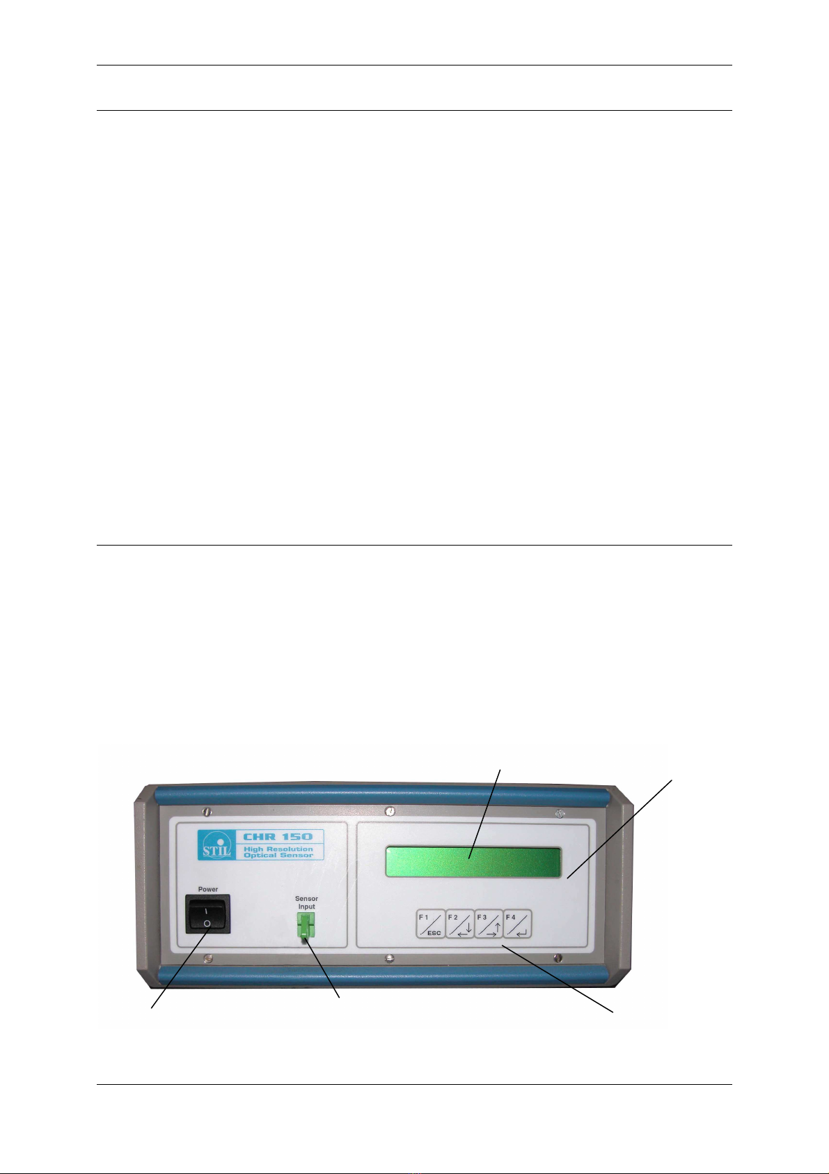
The front panel of the controller features:
Control panel
On-Off switch Optical fiber lead
socket
(“Sensor Input”)
4-keys keypad
LCD display
STIL - CHR 150 – Operating and maintenance manual Doc ref. CHR2-001-P2 Re :D
Page 5 of 49
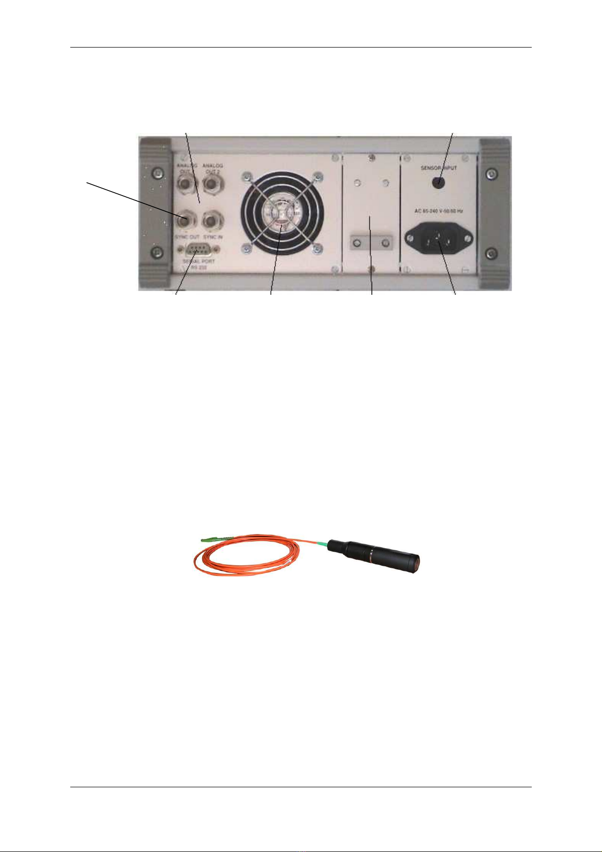
The rear panel of the controller features:
2.2 Optical pen and optical fiber
The optical pen is totally passive, since it incorporates no heat sources or moving parts, thus
avoiding any thermal expansion which could affect the accuracy of the sensor.
When handling the optical fiber lead which links the optical pen to the controller take care to avoid
bending the fiber to a radius of curvature of less than 20 mm. When no optical fiber is connected,
the socket must at all times be fitted with its protection cap to avoid contamination of the fiber tip,
which could result in malfunctioning of the sensor.
84 - 264 V / 50 - 60 Hz mains
input socket
Optional optical fiber Socket
for connecting optical pen
Extractable drawer
providing access to
the halogen lamp
Cooling fan
2 Analog output coaxial
sockets
RS232 SUB-D
9-pin socket
Sync in &
Sync out
Coaxial
sockets

STIL - CHR 150 – Operating and maintenance manual Doc ref. CHR2-001-P2 Re :D
Page 6 of 49
3Safety
The CHR 150 is an opto-electronic instrument. It is safe in normal operating conditions:
3.1 Ther al Hazards
The temperature of the Halogen lamp and its support is very high.
3.2 Electrical Hazards
The CHR 150 controller box should be opened by qualified technicians only.
Electrical hazards might exist, especially during an inappropriate intervention on the instrument.
Unplug the instrument from the power outlet before changing accessories, maintenance, cleaning, or
changing the halogen lamp.
3.3 Optical Hazards
The optical pen emits a beam of visible light with wavelengths ranging from 450 to 900 nm.
The flux contained in this beam is smaller than or equal to 30µW, a value largely under the MPE
(Maximum Permissible Exposure). Thus, independently of the light path inside the room and its
possible reflections, this light beam cannot induce any burn to the skin nor to the eyes.
3.4 General Reco endations
Do not use the instrument if it has been dropped and shows signs of damage or functions improperly.
In this case do not open the instrument and contact our help line: after-sale@stilsa.com
Repairs should only be carried by qualified technicians using original replacement parts.
In case of inappropriate use or failure to comply with the instructions, the manufacturer disclaims all
liability and the guarantee will not apply.
3.5 Co pliance to the EC regulation 89/336/EEC « Electromagnetic Compatibility »
The CHR –150 sensor complies to the generic or specific requirements of the following harmonized
standards
•EN 50 081-1 Spurious emission
•EN 61000-6-2 Resistance to disturbance
Be very careful when changing the halogen lamp in order to avoid the risk of a severe burn.
Switch the power off and let the instrument cool down for about 20 minutes before
attempting to open the lamp drawer.
STIL - CHR 150 – Operating and maintenance manual Doc ref. CHR2-001-P2 Re :D
Page 7 of 49
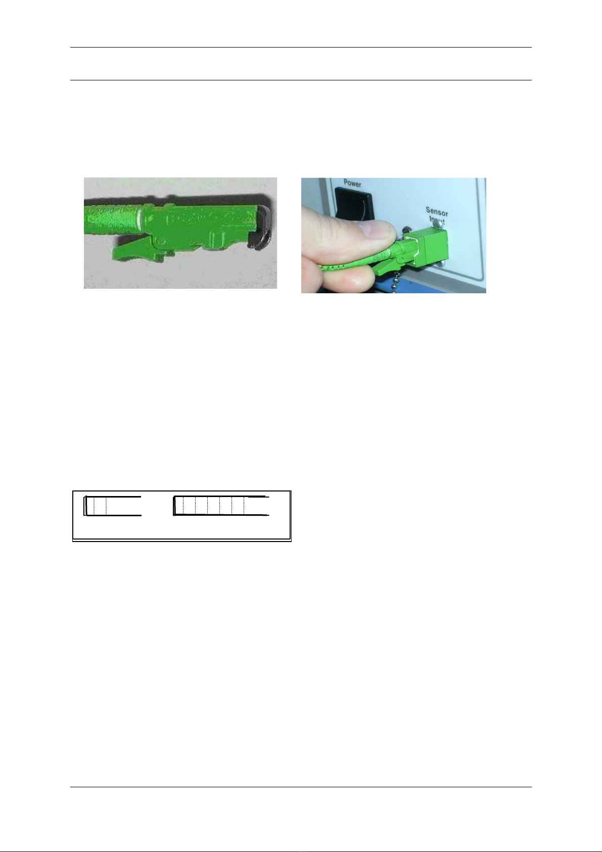
4Installation and switching on
Connect the controller to a mains socket with an earth connection, then connect the optical fiber lead
from the optical pen to the controller, taking care to comply with the correct orientation of the
connector.
Connection and disconnection of the optical fiber lead
To connect the optical fiber lead, simply insert the plug into the socket as shown in figure 1 until a
« click » is heard as it locks into position.
To remove the optical fiber from its socket, first press on the locking lever, then pull the connector
out of the socket.
Warning : When no optical fiber is connected, the socket must at all times be fitted with its
protection cap to avoid contamination of the fiber tip, which could result in malfunctioning of the
sensor.
Switch on the unit by operating the On/Off switch.
When the unit is switched on and after a brief initialisation sequence, the sensor displays the
following screen :
The intensity and distance values are both
displayed as "zero" so long as no object is
present in the measuring field of the sensor.
Int : 0 Dist (um) : 0.00

STIL - CHR 150 – Operating and maintenance manual Doc ref. CHR2-001-P2 Re :D
Page 8 of 49
5Co unicating with the CHR 150
There exist 5 alternative methods for communicating with the CHR 150 sensor:
a) The CHR front panel displays real time measurements and the 4-keys keypad allows a direct
and easy access to sensor configuration.
b) The RS232 serial link enables sensor configuration using a specific control language as well
as acquisition of the measured data . For example, the Windows « Hyper Terminal » utility or
any other utility intended for controlling a serial link can be used to send the commands and
receive the measurements back from the sensor.
c) The « CHR Monitor » optional software is intended for configuring the sensor and launching
measurements in three operating modes (continuous visualisation, « point by
point” measurement, acquisition of a temporal profile). It can also be used to display, save and
print-out the measurements.
d) The optional « CHR DLL » optional software is used to interface the sensor with a general
purpose user program in C++ language or similar. The operating manual of the DLL includes a
large number of code samples.
e) Finally, the « CHR Setup » optional software can be used for viewing the signal from the on-
board spectrometer and for downloading new firmware versions and new calibration tables.
These advanced features may be useful for some specific applications.
For further details regarding available software, please visit our web site
http://www.stilsa.com/
.
Recommendation : All the software applications use the same COM port to communicate with the CHR
150. Remember to always free the port by quitting one application before attempting to connect it to
another application.

STIL - CHR 150 – Operating and maintenance manual Doc ref. CHR2-001-P2 Re :D
Page 9 of 49
6Getting started (Tutorial 1)
This chapter is a tutorial intended for new users who wish to familiarise themselves with the main
characteristics of the CHR 150 sensor. For simplification purposes, this tutorial only introduces one
measuring mode (« Distance » mode) and one communication method (the control panel). We
recommend that new users follow this tutorial even if they wish subsequently to use another measuring
mode or a different method for communicating with the sensor.
6.1 Using the control panel
Press any key to access the control panel main menu:
As symbolised on the keypad, each key has its own main function:
F1 = Escape
F2 = Increase displayed value or move the cursor to the left
F3 = Decrease displayed value or move the cursor to the right
F4 = Enter.
Besides, each function displayed on the LCD display can be launched by the keys just bellow it. As an
example in the main menu shown above:
F1 may be used to clear the menu,
F2 to launch acquisition of the ” Dark” signal,
F3 to set sampling rate
F4 to enter the configuration menu, which allows setting all sensor parameters.
When configuration of the sensor is complete, the sensor prompts the operator to save the
modifications made by displaying the following message "Save settings in EEPROM ?". If the "Yes" key
is pressed, the modifications are saved permanently, otherwise the modifications are lost as soon as
the CHR 150 is switched off.
The entire menu-trees are presented next pages.
Clear Dark S.Rate Config.
F1 F2 F3 F4
LCD display
4-key
Keypad
E
sc

STIL - CHR 150 – Operating and maintenance manual Doc ref. CHR2-001-P2 Re :D
Page 10 of 49
S.R
ATE
1000H
Z
300H
Z
100H
Z
30H
Z
Free/Double
Exposure
CCD Scan Rate
Cycle
Frequency
Set E.Time
Ratio
Set Rate Menu
C
ONFIG
C
LEAR
S.R
ATE
D
ARK
MAIN
Main menu
F1
F3
F2
F4
•To access the Main menu of the Control panel, press any key.
•The S.Rate and the configuration menus are both described below.
F2 F3

STIL - CHR 150 – Operating and maintenance manual Doc ref. CHR2-001-P2 Re :D
Page 11 of 49
C
ONFIG
.
Data
averaging Take white
reference
Set default
parameters
LCD
Contrast
Config.
Analog
out1
Serial port
Baud Rate
Set
detect.
threshold
Serial data
ASCII/BIN
Set serial
output
data
Select
measuring
mode
Select
confocal
sensor
Spectral
averaging
Config.
Analog
out2
Configuration Menu
F2 F3

STIL - CHR 150 – Operating and maintenance manual Doc ref. CHR2-001-P2 Re :D
Page 12 of 49
6.2 Selecting the optical pen
The CHR-150 controller may hold up to 6 calibration tables corresponding to 6 different optical pens.
Available optical pens and their characteristics may be consulted in STIL website : www.wtilsa.com.
Optical pens are passive devices and the controller can not identify the optical pen which is physically
connected to it, so the operator has to select the calibration table corresponding to the optical pen that
is physically connected.
To configure the controller to right optical pen using the control panel:
Press any key to access the Main menu,
Press F4 to enter the Configuration menu,
Press F2 until you reach the ‘select confocal sensor’ window (if you reach the last menu option,
change the sense and press F3 until you reach this window).
Press F4 to enter the ‘‘select confocal sensor’
Use F2 or F3 to select the desired optical pen.
Validate with F4 or F1
6.3 configuring of the sensor in « Distance » easuring ode
The next step is to configure the sensor to the desired measuring mode. For distance measurement
select the “Distance” mode (‘confocal, 1 surface’).
In the configuration menu, press F2 (or F3) until you reach the ‘select measuring mode’
window
Check that ‘confocal, 1 surface’ is displayed then validate with F1 or F4. Otherwise press F2
or F3 until you see ‘confocal, 1 surface’ displayed.
Next, check that the averaging factor is set to 1 (no averaging in the ‘data averaging’ window).
The last step in sensor configuration is setting sampling rate.
To select the ‘S.Rate’ menu, exit the configuration menu using the F1 key. In the Main menu
select ’S. Rate’ (F3). The currently selected rate is displayed: ‘CCD-SCAN rate : XXXX Hz’.
Use F2 and F3 to view the available rates, and note the existence of the ‘free/double
frequency’ option. For the moment, we wish to select the lowest rate (30Hz).
Use F2 several time to select this rate, and validate with F1 or F4.
Sensor configuration is done. When quitting, save the current configuration to the EEPROM.
6.4 Recording the dark signal
The dark signal of the sensor represents an intrinsic offset level generated by parasitic light in the
sensor, which must be taken into account for the sensor to be able to operate correctly. The level of
the Dark signal depends on the sampling rate. The dark signal should be recorded at all measuring
rates, in order to be able to subtract it while the sensor is measuring.
A dark signal acquisition is performed during adjustment by the manufacturer, but must be repeated at
regular intervals in order to compensate for the halogen lamp ageing phenomenon.
In order to perform a dark signal acquisition, it is essential for there to be nothing within the
measurement field or even better, to blank off the light beam by applying a piece of paper over the tip
of the optical pen.
Press any key to access the main menu, followed by F2 to enter the ‘Dark’ menu.
Blank off the light with a piece of paper, then press F4 to start dark acquisition. The sensor then
records the dark signal over a few seconds. A message is displayed to indicate the end of this
operation. The piece of paper can now be removed and the sensor can be used in the normal way.
Warning : If on completion of the dark recording sequence, a warning message appears indicating that
there is too much light for a given sampling rate, this means that the dark signal is too high for working
at lower rates. This is generally caused by the presence of dust or impurities at the ends of the optical
fiber generating stray light reflections which interfere with correct operation of the sensor.
STIL - CHR 150 – Operating and maintenance manual Doc ref. CHR2-001-P2 Re :D
Page 13 of 49
Int. : 38
Dist. (um) :
135.00
Clean the ends of the optical fiber as described in the maintenance section of this manual, then repeat
the dark signal acquisition and check that the warning message does not reappear.
A different cause for such a warning may be that the optical pen lens was not entirely blanked off.
Recommendation : The dark signal acquisition procedure should preferably be performed at least
a quarter of an hour after switching on the sensor, in order to ensure that the temperature and the
optical characteristics of the halogen lamp have stabilised.
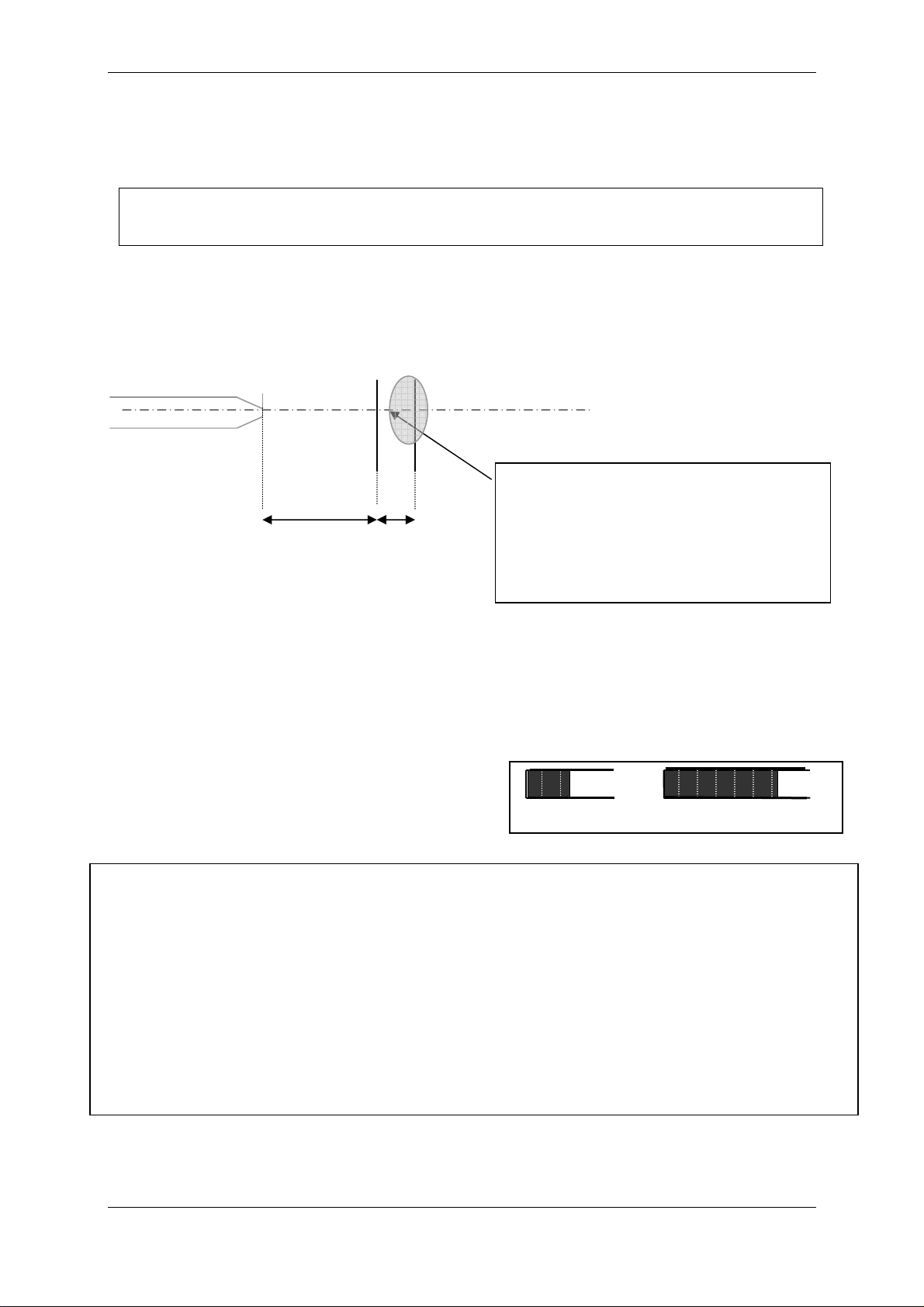
6.5 Positioning the sa ple within the easure ent range of the optical pen
Mount the optical pen on a suitable support (for example, a « V » block). Position the sample to be
measured in front of the pen, and move it forward or backward until the working distance is reached.
For pens with a millimetric measurement range, the positioning of the object within the measurement
range of the optical pen is easy to achieve, simply observe the luminous spot focused on the object by
the optical pen: as the measuring range is approached, the spot becomes smaller and smaller and its
intensity increases.
For optical pens with a micrometric measurement range, the operation is more difficult : position the
sample on a stable support on a small manually translating bed, with a suitable pitch lead screw.
As soon as the sample enters the optical pen's
measurement field, the Distance and intensity
measured are displayed on bar-graphs and digital
indicators on the LCD display.
The zone of the sample to be measured
must be located in front of the optical
pen, within the measurement range of the
pen. Its distance from the optical pen
should be approximately equal to the
working distance of the pen.
Optical axis
Optical pen
Working
distance
Measurement
range
Recommendation : If no measurement is displayed when the object is within the measuring field of the
sensor, check the following points :
•The optical fiber cable connector is fully plugged into the socket on the front panel.
•A light beam is emitted from the tip of the optical pen and the spot is focussed on the sample.
•The distance between the tip of the optical pen and the surface of the sample is equal to the
working distance specified in the table above.
•The optical axis is normal to the surface of the sample. The local slope must be less than the
“max slope” indicated in the table.
•The sampling rate selected is the lowest shown in the list (30 Hz), the measuring mode selected is
‘Confocal, 1 surface’ mode.
•The displacement pitch of the translation bed carrying the sample is suitable for the measurement
(for example, for pen model OP 020, the pitch must be ≤5 µm)
•
The Dark signal has been correctly acquired.

STIL - CHR 150 – Operating and maintenance manual Doc ref. CHR2-001-P2 Re :D
Page 14 of 49
6.6 Understanding the eaning of the intensity easure ent
The « Intensity » parameter measured by the sensor is an indication of the brightness of the signal
reflected back off the sample, as a percentage of the dynamic response of the sensor. Its value is
dependent on several parameters:
•The sampling rate of the sensor
•The local slope on the sample (angle between the optical axis and the normal to the
surface at the point of impact)
•The reflectivity of the sample at the detection wavelength λ
o
•The brightness of the halogen lamp at wavelength λ
o
•The response of the spectrometer at wavelength λ
o
The detection wavelength λo varies within the measurement range. Thus it is not surprising that the
intensity measured at a given point on the sample varies when the latter is moved within the
measurement range of the optical pen.
For each point in the measurement range, the value of the intensity varies between 0% and a
maximum value I
sat
. Beyond that, the sensor is saturated. The state of saturation is indicated by an
intensity value of 100% as shown in the graph below :
The value of I
sat
is dependent on the detection wavelength λo, and may vary slowly within the
measurement range of the sensor.
Example : If the intensity measured oscillates between 100% to 60%, this means that I
sat
= 60% and
that the sensor is on its saturation limit : in such case, select a higher rate.
6.7 Adjusting the sa pling rate
When the sample is within the measurement range of the optical pen, adjust the sampling rate :
Modify the sampling rate selected in the ‘CCD SCAN Rate’ window of the control panel, and observe
the value of the intensity displayed.
The first tutorial is over. In this tutorial you have learned how to:
Use the control panel to configure the sensor,
Select the rate and the optical pen,
Record the ‘Dark’ signal
Position the sample with the measuring range of the optical pen
Use the ‘Intensity’ data to adjust the measuring range.
0% Reflectivity of the sample
100%
100%
I
sat
Intensity measured by the CHR 150
0%
Recommendation : The intensity is a good indicator of the measurement quality : It should
be as high as possible, without, however reaching saturation level.
Recommendation : Always select the lowest rate for which the signal does not saturate.

STIL - CHR 150 – Operating and maintenance manual Doc ref. CHR2-001-P2 Re :D
Page 15 of 49
7Going further (Tutorial 2)
This chapter is a tutorial intended for users having acquired some initial experience with the CHR 150
sensor in the “Distance” measuring mode. This tutorial covers the following topics :
•“Thickness” ( “Confocal, 2 surfaces” ) measuring mode
•“Interferometric” and “Min/max” optional measuring modes.
•Communication with the sensor via the RS232 serial link using the Windows « Hyper
Terminal » utility.
•Synchronisation signals (« Trigger » ).
7.1 Measuring odes
The main measuring mode for the CHR 150 sensor is “Distance” mode . The sensor is calibrated and
tested by the manufacturer in this measuring mode, and a certificate of the test results is supplied with
each optical pen.
In order to measure the thickness of flat transparent or semi-transparent samples, the CHR provides
two additional measuring modes « Thickness », available as standard, and « Interferometric » mode,
available as an option. In both these modes the refractive index of the sample must be known.
The last measuring mode, « Min/max mode », dedicated to on-line measurement of the thickness of
transparent objects, is also available as an option. This mode enables the measurement of the
minimum and maximum thickness measured within a time window determined by the operator, and
comparison of these values with the thresholds established by the operator.
CHR sensor measuring modes
Measuring mode Distance Thickness Min/max Interferometric
Optical principle Confocal microscopy with chromatic encoding White light
interferometry
Pen models All confocal mode pens Interferometric
pen
CHR models All All
CHR 150,
CHR 150 -PC
CHR 150,
CHR 150 -PC
Availability Standard Standard Optional Optional
Simultaneously
measured
data items
Distance,
Intensity,
Barycenter (*)
Thickness,
Distance face 1,
Distance face2,
Intensity face 1,
Intensity face 2,
Barycenter face 1 (*)
Barycenter face2 (*)
Min. thickness
Max. thickness
Thickness,
Intensity
Quality indicator
Metrological test
with certificate
Yes
No
No
No
Application Distance
measurement
(surface
roughness,
microtopography)
Thickness
measurement from
~25 µm
On-line
thickness
measurement
Thickness
measurement
from ~2 µm
(*) Data items used by the manufacturer for calibration of the sensor.

STIL - CHR 150 – Operating and maintenance manual Doc ref. CHR2-001-P2 Re :D
Page 16 of 49
7.2 Configuring the sensor in “Thickness” easuring ode
In this measuring mode the sensor searches for 2 signals, reflected from the 2 faces of the sample. If
they are found, it calculates the intensity and Distance of face 1 (front face, i.e. the nearest face), the
Distance and intensity of face 2 (rear face), and the thickness. All these data are available
simultaneously.
If the sensor can only detect one signal, all the data are reset on zero. This can occur if one or other
face of the sample is located outside the measurement range.
The thickness of the sample must be compatible with the thickness measurement range of the optical
pen used:
As a general rule, the maximum thickness which can be measured is proportional to the refractive
index of the material. Thus, for an OP1000 optical pen, whose measurement range in air is 1 mm, one
can measure the thickness of a sheet of glass up to ~1.5 mm.
If the thickness of the sample is less than the « Minimum thickness » limit specified the sensor is
unable to resolve the two signals reflected from the two faces of the sample and considers them as a
single signal. Output will be set on zero.
Experimentation:
•To select the “Thickness” measuring mode, press any key, then F4. Next, use F2 and F3 to
display ‘Select measuring mode’, enter with F4 and select the “Thickness” mode (‘Confocal 2
surfaces’) using F2 or F3 then validate with F1 or F4. The LCD Screen displays ‘refractive
Index’, enter the value of the refractive index of the sample, then click on « OK » to close the
configuration window.
•Position a thickness sample in the measurement range of the optical pen, such as a glass
slide, a piece of cellophane, a transparent plastic film or any other flat transparent sample. If it
is a sheet or film, ensure it is pulled tight. Also check that the axis of the optical pen is normal
to the surface of the sample. The sample thickness should be in the range specified in the
table above.
•Slowly move the object to position both faces within the measurement range, and to obtain two
signals of comparable intensity. If the signal saturates, adjust the sampling rate.
Warning : To obtain a valid measurement in « Thickness » mode, the refractive index of the
sample must be accurately known.
Recommendation : If you manage to obtain a measurement in “Distance” mode (‘Confocal,
1surface’) but in “Thickness” mode (Confocal, 2surfaces) the thickness is zero, check the
following points :
•The thickness of the sample must be compatible with the measurement range limits
(see the table).
•The sample must be sufficiently transparent.
•The sample must be pulled tight.
•The optical axis must be normal to the surface of the sample.
•The sampling rate selected in the « Sensors » window must be the lowest in the list
(30 Hz).
Recommendation : In « Thickness » mode, center the sample within the measurement range
of the pen, avoid having either one of the faces close to the limits of the range.

STIL - CHR 150 – Operating and maintenance manual Doc ref. CHR2-001-P2 Re :D
Page 17 of 49
7.3 Configuring the sensor in « Interfero etric » easuring ode
The “Interferometric” measuring mode is optional. If your sensor is not equipped with this
option, skip to the next section (§7.4).
To select the Interferometric measuring mode, press any key, then F4. Next, use F2 and F3 to display
‘Select measuring mode’, enter with F4 and select the Interferometric mode using F2 or F3 then
validate with F1 or F4. At that step, enter the refractive index and press F1.
This measuring mode is dedicated to thickness measurement of transparent coatings or transparent
films, whose thickness is within the range 2 to 100 µm approximately, for a refractive index of 1.5 (3 to
150 µm in air). It requires the use of a specific achromatic optical pen, and a signal processing
algorithm specific to this mode.
In this measuring mode the sensor calculates an intensity value, a quality indicator and a thickness,
(actually it calculates 3 quality indicators for 3 theoretical possible thicknesses. The second and third
thicknesses are significant for multi-layer samples only).
The « Interferometric » optical pen is equipped with a removable tip which enables it to work in contact
with the object. Its working distance is about 42 mm.
Tip Adjustment Procedure:
In order to ensure good quality measurements, it is essential to comply with the following adjustment
procedure :
•Connect up the « Interferometric » optical pen to the sensor.
•Select the “interferometric” measuring mode ( ‘Interfer. thickness ‘).
•Acquire the « Dark » signal.
•Approach the optical pen to the sample in order to obtain a non zero "Intensity" signal.
•Adjust the distance by screwing the tip in or out in order to maximise the intensity
measurement.
•According to the reflectivity of the object being measured, adjust the sampling rate in order to
obtain maximum intensity without saturation.
Warning : If the sensor saturates (Intensity = 100%), measurement becomes impossible.
•Finally adjust the distance by screwing the tip in or out in order to maximise the measurement
quality parameter. The optimum distance obtained by maximising the « Quality» parameter
may be slightly different from that corresponding to maximum intensity. When the adjustment
is optimum, tighten the locknut in order to lock the tip in that position.
The equipment is now ready to perform thickness measurement.
Measurement
Take the sample to be measured and position the « Interferometric » optical pen equipped with its tip
in contact with the point to be measured. The optical pen must be positioned strictly perpendicular to
the surface of the object. In order to find the correct position, slowly pivot the optical pen around the
point looking for the maximum intensity value. As soon as an available measurement is detected, the
Quality indicator and the Thickness value are displayed.
Bracketed mode
In order to stabilise the measurements when the quality factor is low, it is possible to "bracket" the
thickness measuring range using the keypad:
Key F4 is pressed to switch successively between bracketed mode (with black bases representing the
excluded values) and non-bracketed mode.
It is also used for adjusting alternately the right hand or left hand limit of the window.
Keys F2 and F3 are then used for displacing the edges of the valid thickness window respectively to
the left or to the right.

STIL - CHR 150 – Operating and maintenance manual Doc ref. CHR2-001-P2 Re :D
Page 18 of 49
Example : starting from non-bracketed mode
F4 bracketed mode, LH edge selected
F2 displacement of the LH edge to the left
F3 displacement of the LH edge to the right
F4 non-bracketed mode
F4 bracketed mode, RH edge selected
F2 displacement of the RH edge to the left
F3 displacement of the RH edge to the right
7.4 Configuring the sensor in « Min/ ax » easuring ode
The “Min/max” measuring mode is optional. If your sensor is not equipped with this option,
skip to the next section (§7.5)
This mode is dedicated to on-line measurement of the thickness of transparent objects.
To select the Min/Max mode, press any key, then F4. Next, use F2 and F3 to display ‘Select measuring
mode’, enter with F4 and select the Min/Max mode using F2 or F3 then validate with F1 or F4.
« Min/max » measuring mode is used to determine the minimum thickness and maximum thickness
measured. In this mode the sensor permanently measures the objects passing beneath the optical
pen, but only records the extreme values observed. These values are compared with two thresholds
(maximum thickness and minimum thickness) preset by the operator, in order to identify the objects
exceeding these limits.
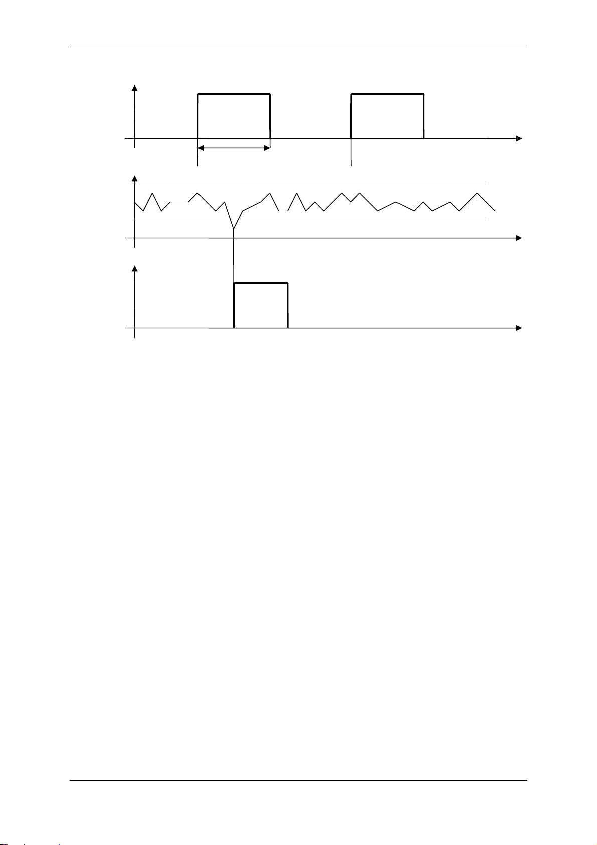
The « Activate inspection » input determines the time interval for thickness measurement. In the
« Closed » state, the sensor saves the minimum and maximum thickness values measured, and
compares them in real time with the two thresholds defined by the operator. If a thickness
measurement exceeds these limits, the « Defect » output signal is activated, triggering for example
ejection of the object off the production line.
At the end of the measurement (i.e. when the « Activate inspection » input returns the « open » state)
the min. and max. thicknesses are transmitted via the serial link as data 7 and 8 (see. « Select output
data »).
7.4.1 Signal specifications
•The « Activate inspection » input and « Defect » output replace, respectively, the « Sync in »
input and « Sync out » outputs.
•« Closed » state of the « Activate inspection » input : the 2 pins for this signal are short-
circuited or connected together by an impedance of less than 100 ohms. The sensor delivers a
voltage of 5V into an impedance of 1 kOhm, thus limiting the current to 1 mA.
•« Defect » output : This output is connected to both pins of an insulated static relay. It switches
to the « Closed » state as soon as a defect (exceeded threshold) is detected. The maximum
external load for this output is 40V DC and 0.5 Amp.
STIL - CHR 150 – Operating and maintenance manual Doc ref. CHR2-001-P2 Re :D
Page 19 of 49
The diagram below shows an example of the operating sequence :
7.4.2 Experi enting with « Min/ ax » easuring ode
A) Prepare a thickness sample and determine the min. and max. thicknesses
•Connect an optical pen to the sensor, select the optical pen in the ‘Select confocal sensor’
window of the control panel configuration menu
•Configure the sensor in “Thickness” measuring mode (‘confocal, 2 surfaces’).
•Execute a « Dark » signal measurement.
•Place a variable thickness transparent sample within the measurement range of the optical
pen (for example, an ophthalmic contact lens, a bottle or a glass). The thickness must be
compatible with the thickness measurement range of the optical pen (see ‘Configuring the
sensor in “Thickness” measuring mode’).Configure the sensor for the refractive index of the
sample.
•Centre the sample within the measurement range and adjust the sampling rate.
•Move the sample horizontally in order to measure the thickness variation from one point to the
next on the sample. Record the min. value (E0) and max. value (E1) of the thickness.
B) Configure the sensor in « Min/max » mode
•Connect the coaxial “Sync in” plug (« Activate inspection» input) to a switch in order to be able
to switch from the « Closed » state to the « Open » state (cf. « Signal specifications »).
Ensure that the input is Open.
•Configure the sensor for « Min/max » measuring mode
•Adjust the thickness thresholds to E0*0.5 and E1*1.5, respectively.
•Select the « Min. thickness » and « Max. thickness » data for the bargraphs of the « Sensors »
window.
C) Use the « Defect » output
•Stop the measurement
•Connect the “Sync out” plug (« Defect » output signal) to an ohmmeter (cf. « Signal
specifications »)
•Start the measurement.
•Move the sample horizontally and observe the ohmmeter : the resistance measured should be
infinite.
•Stop the measurement
T1
Max threshold
« Defect »
signal
« Activate
inspection »
signal
Min threshold
Thickness
Defect
detected
Inspection
activated No
inspection Inspection
activated
No
inspection No
inspection
No defect
Table of contents
Popular Accessories manuals by other brands

PCB Piezotronics
PCB Piezotronics HT356A26 Installation and operating manual
 specification")
Panasonic
Panasonic Switching Diodes MA4X174 (MA174) specification

Philips
Philips DLA91000H Specifications

RIB
RIB ACG2275 quick start guide

Garmin
Garmin GRF 10 installation instructions

PSI Woodworking Products
PSI Woodworking Products PKFUNSET instructions

Master Grade
Master Grade Pro user manual

Promate
Promate Provolta-21 user guide

Airmar
Airmar WeatherStation 110WXS Owner's guide and installation manual

Royal Catering
Royal Catering RCCC-160ST user manual

NTI
NTI SPLITMUX-DVI-4RT Installation and operation manual

Liberty Safe
Liberty Safe Safe Power Outlet Kit Installation and operation manual


