STILLE 6300 Series User manual

Service Manual
Gynaecology/Urology Table 6300 series
Urodymanics Table 6202

2(56)
Contents
Safety Information ......................................................................................................................................................3
Safety Information (continued)..................................................................................................................................4
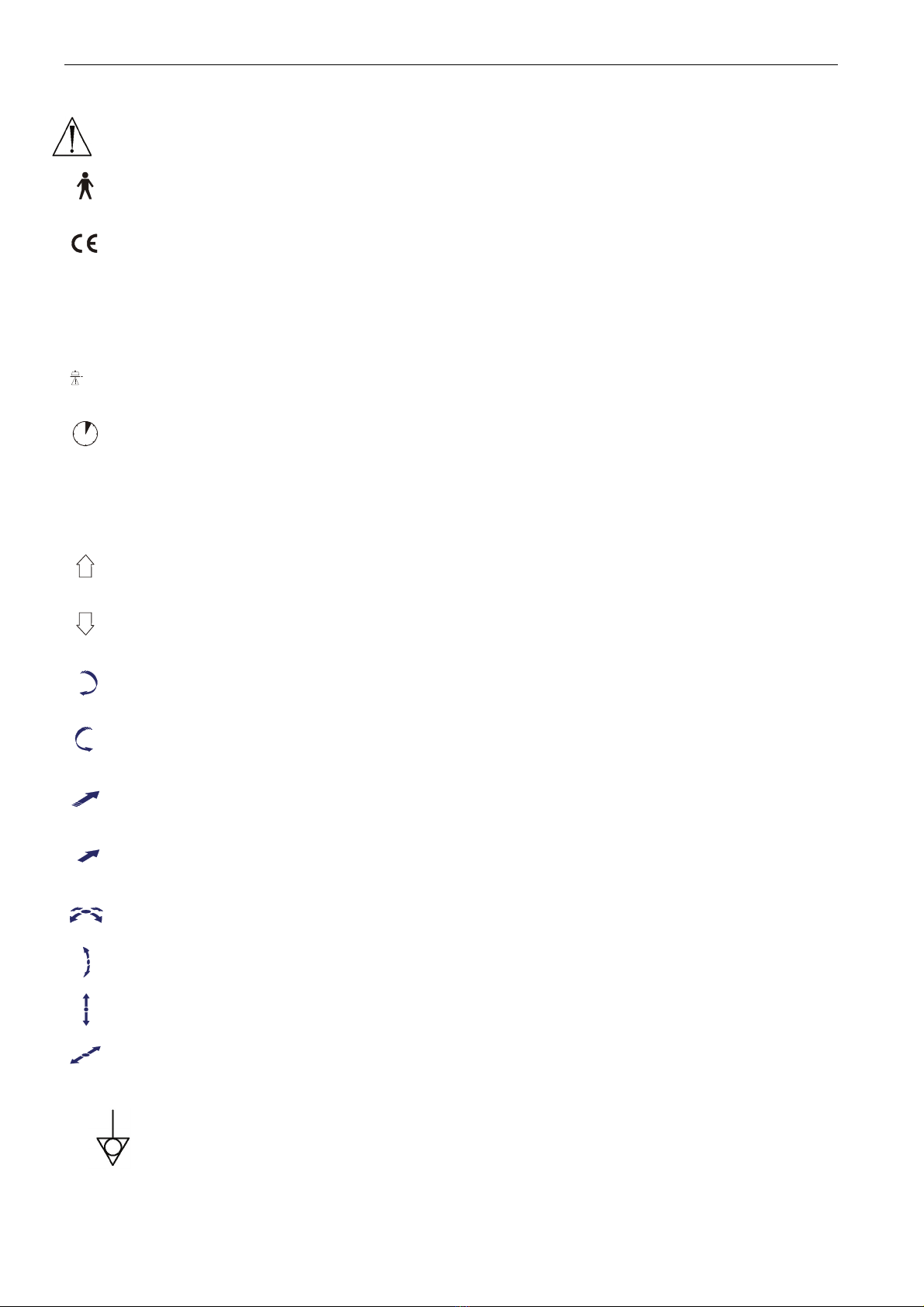
Symbols (General)......................................................................................................................................................5
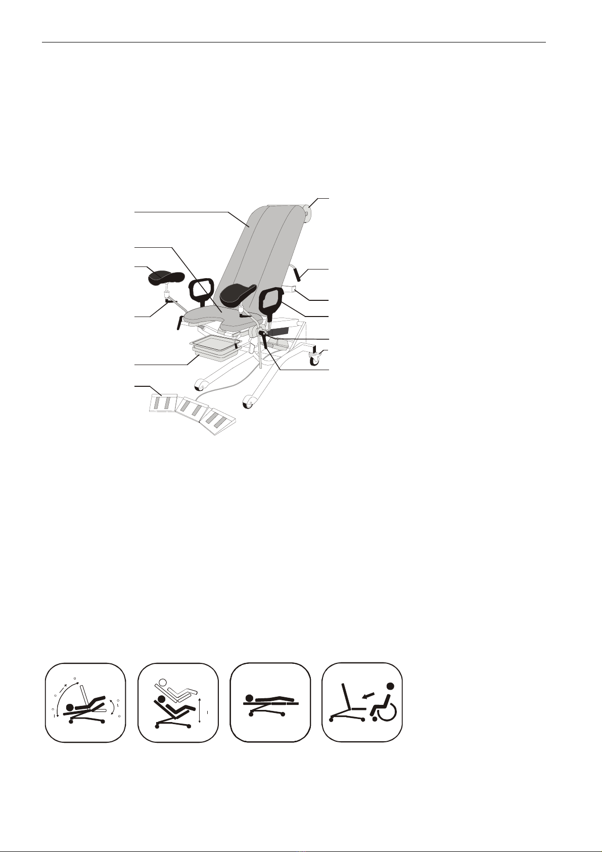
System Description Gynaecology/Urology table 6300 Series ................................................................................6
Description........................................................................................................................................................................................6
Operation range:...............................................................................................................................................................................6
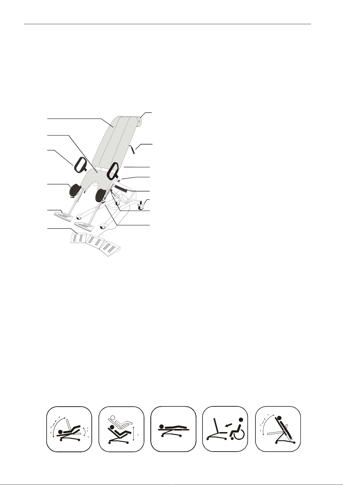
System Description Urodymanics Table 6202 .........................................................................................................7
Description........................................................................................................................................................................................7
Operation range:...............................................................................................................................................................................7
Technical Data ............................................................................................................................................................8
Model................................................................................................................................................................................................8
Power Supply ...................................................................................................................................................................................8
Operating Conditions........................................................................................................................................................................8
Storage Conditions /Transportation Requirements ..........................................................................................................................8
Disposal (backup battery, battery drive system (optional))....................................................................................8
Measures and weights......................................................................................................................................................................8
Classification ....................................................................................................................................................................................9
Maintenance..............................................................................................................................................................10
Cleaning .........................................................................................................................................................................................10
Preventive Maintenance .................................................................................................................................................................10
Acronyms, definitions .....................................................................................................................................................................10
Preventive maintenance instruction and record .............................................................................................................................11
Trouble shooting ......................................................................................................................................................12
Initial information: ...........................................................................................................................................................................12
Start by checking the obvious things first: ......................................................................................................................................12
Symptoms.......................................................................................................................................................................................12
What to do ......................................................................................................................................................................................12
Symptom “Controls do not operate the table”.................................................................................................................................13
Symptom “lift, seat or back motor not operating properly” .............................................................................................................15
Symptom “Foot rests not operating or have other problem"...........................................................................................................16
Symptom “Gas pistons will not operate or have other problem” ....................................................................................................17
Symptom “Wheels have reduced braking ability or other problem”................................................................................................17
Removal and Replacement ......................................................................................................................................18
Initial information: ...........................................................................................................................................................................18
Removal and replacement procedures...........................................................................................................................................18
Removal/replacement list ...............................................................................................................................................................18
What to do ......................................................................................................................................................................................18
Remove/Replace power cord .........................................................................................................................................................19
Remove/Replace Foot control/ Hand control..................................................................................................................................20
Remove/Replace Control box.........................................................................................................................................................21
Remove/Replace Lift motor ............................................................................................................................................................22
Remove/Replace Seat motor .........................................................................................................................................................23
Remove/Replace Back motor.........................................................................................................................................................24
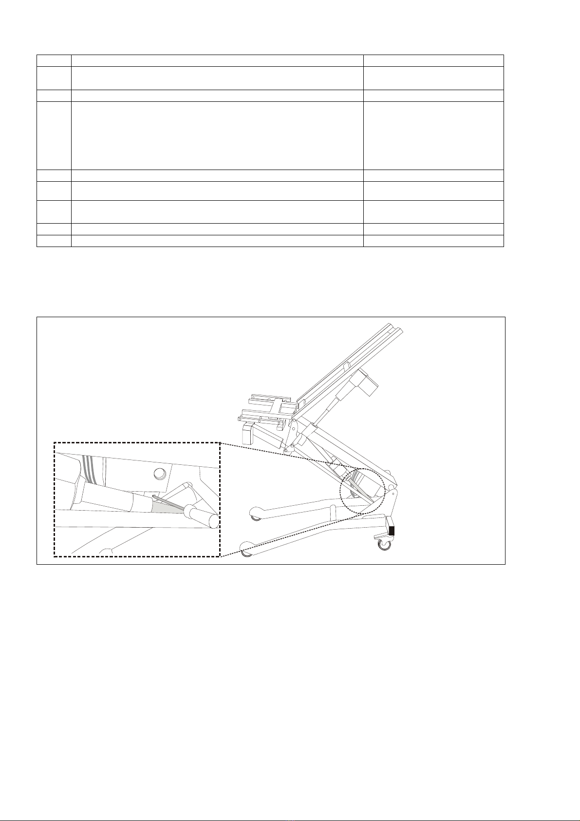
Remove/Replace Gas piston..........................................................................................................................................................25
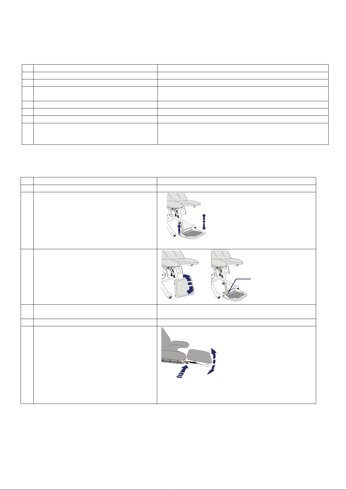
Remove/Replace Gas piston for foot rest.......................................................................................................................................26
Remove/Replace Back cushion......................................................................................................................................................28
General Assembly for Table 6300-series................................................................................................................29
Assembly, Bottom frame Table 6300-series...................................................................................................................................30
Part list............................................................................................................................................................................................31
Complete Assembly, 3-motors Table 6300-series..........................................................................................................................32
Part list............................................................................................................................................................................................33
Part Assembly, 3-motors Table 6300-series ..................................................................................................................................34
Part List ..........................................................................................................................................................................................35
Complete Assembly, 2-motors Table 6300-series..........................................................................................................................36
Part List ..........................................................................................................................................................................................37
Part Assembly, 2-motors Table 6300-series ..................................................................................................................................38
Part List ..........................................................................................................................................................................................39
Complete Assembly, 2-motors (fixed seat) Table 6300-series......................................................................................................40
Part List ..........................................................................................................................................................................................41
Part Assembly, 2-motors (fixed seat) Table 6300-series ...............................................................................................................42
Part List ..........................................................................................................................................................................................43
Electrical System Diagram 230/120 V ~ Table 6300-series ...........................................................................................................44
General Assembly for Table 6202 ...........................................................................................................................45
Assembly, Complete 6202..............................................................................................................................................................46
Part list 6202...................................................................................................................................................................................47
Part Assembly (1 of 2) 6202 ...........................................................................................................................................................48
Part List (1 of 2) 6202 .....................................................................................................................................................................49
Part assembly (2 of 2) 6202 ...........................................................................................................................................................50
Part List 6202 .................................................................................................................................................................................51
Assembly, Bottom frame 6202 .......................................................................................................................................................52
Part List 6202 .................................................................................................................................................................................53
Electrical System diagram 230/120 V~ Table 6202 .......................................................................................................................54
Notes: .............................................................................................................................................................................................55
Service Centers ..............................................................................................................................................................................56

3(56)
Safety Information
Copyright ©2009 Stille Sonesta AB. All rights reserved.
The contents of this manual are the property of Stille Sonesta AB. Any reproduction in whole or in part is strictly
prohibited.
At the time of printing, this manual correctly described the device and its functions. However, as modifications
may have been carried out since the production of this manual, the system package may contain one or more
amendments to the manual. This manual including any such amendments must be thoroughly read, before ser-
vicing/using the device.
Stille Sonesta AB is only responsible for reliability and performance of the device if following are observed:
•Authorized personnel (see back of manual for authorized service centers) carry out all repairs and modifi-
cations.
•Use only Stille Sonesta spare parts.
•The device must be used in accordance with intended use and standards put forth in the Safety Informa-
tion section.
This manual contains different icons and typefaces designed to improve readability and increase understanding
of its content. Adhere to the following recommendations and the ones in the User Manual for safe operation of
the device and service: See below and in the user manual.
NOTE: Sets apart special information or important instruction clarification.
WARNING symbol identifies situations or actions that may affect patient or user safety. Disregarding a
warning could result in patient or user injury.
CAUTION Symbol points out special procedures or precautions that personnel must follow to avoid
equipment damage.
CAUGHT WARNING. The symbol highlights a risk of physical danger to the user or operator (ensure
that hands, feet and equipment are clear of the frame assemblies when changing positions of the ta-
ble, always engage the brakes, verify the stability after brakes are engaged, except during transport).
DISPOSAL CAUTION: The symbol highlights a disposal procedure or recommendation that must be
followed.
LIFTING WARNING. The symbol highlights a risk of physical danger to the user or operator
when lifting parts or table. Use proper lifting methods.
If the above points are not strictly observed, the warranty will be considered invalid.

4(56)
Safety Information (continued)
Only facility-authorized personnel should troubleshoot the Stille Sonesta 6300 series/ 6202 tables.
Troubleshooting by unauthorized personnel could result in personal injury or equipment damage.
Follow the packaging/ un-packaging procedure to avoid personal injuries, equipment damage or property
damage.
Never use the device near mobile telephones, CB radios or other forms of radio communication, and/or
electromagnetic fields. These may affect the performance of the device.
Do not attempt to open the control box or actuators.
Do not immerse the control unit device in water or any other liquid (See the Maintenance/Cleaning section
for specific details).
The power connector also serves as the main power switch i.e. remove connector to power off.
Unplug the power connector from its power source before cleaning or servicing. Failure to do so could re-
sult in equipment damage.
Ensure that the power cord does not become pinched between mechanisms during normal operation of
the table. Failure to do so can result in equipment damage.
Do not connect the power connector or any control unit connector to anything other than the appropriate
input on the device.
The table is only to be used with medical equipment complying with EN 60601-1. EN 60601-1-2.
The device is not intended for use with flammable anesthetic gases. A possible explosion hazard exists
and personal injury or equipment damage could occur.
Ensure that the table is in its lowest position if the patient is unattended.
Ensure that hands, feet and equipment are clear of the frame assemblies when changing positions of the
table.
Always engage the brakes, verify the stability after brakes are engaged, except during transport.
Use only Stille Sonesta spare parts.

5(56)
Symbols (General)
Explanations of the symbols found on the body of the device:
Attention, see accompanying documents.
Type B, equipment providing a particular degree of protection against electric shock
The device complies with the EC directive 93/42/EEC on medical devices.
IP66
Degree of protection, EN 60529 (ingress of water and foreign objects)
170 kg
Max safe workload icon, max safe workload 170Kg.
6 Min/H
Duty cycle icon, duty cycle 6 min/H or 10%
Explanations of the symbols found in the user manual:
Moves said part, up.
Moves said part, down.
Secure.
Release
Push.
Insertion direction (part)
Adjustable in shown directions
Potential equalization connection point

6(56)
System Description Gynaecology/Urology table 6300 Series
The Stille Sonesta 6300 Series tables are intended for Gynecology and/or Urology examinations and proce-
dures. An electric motor is used to adjust the height of the table. An electric motor (optional fixed) is used to
adjust the angle of the seat cushion. An electric motor (optional gas piston operated) is used to adjust the angle
of the back cushion. The motor for the back cushion has a quick release level for Trendelenburg like positioning.
The Stille Sonesta 6300-series are available with 120V 60 Hz or 230V 50 Hz transformers and hospital-grade
plugs. The transformer reduces the electrical voltage to the motors to 24V DC.
The table uses foot or hand controls (model dependant) to set the table and patient in the desired position, see
description of controls. For accessories, installed or delivered separately, see accessories list and installation.
1
2
3
4
5
6
7
8
9
10
11
12
13
Description
1. Back cushion.
2. Seat cushion.
3. Rissler leg rest.
4. Leg rest adjustment screw. Use hand screw to secure and to release.
5. Drainage receptacle container and holder.
6. Foot control (model dependant).
7. Adjustable paper roll holder.
8. Back cushion release handle. Push lever towards the cushion to release (model dependant).
9. Quick release (Trendelenburg like position). Push lever towards the cushion to release (model dependant).
10.Arm rest.
11.Arm rest adjustment screw. Use hand screw to secure and to release.
12.Locking mechanism for wheels.
13.Lever for adjusting the leg rest. Use lever to secure and to release. Pulling out the lever allows the lever
position to be changed.
Operation range:
8
32
0
0,4 1,0m
70
(-12)

7(56)
System Description Urodymanics Table 6202
The StilleSonesta 6202 table is intended to be used during urodynamic examinations and procedures. An elec-
tric motor is used to adjust the height of the table. An electric motor is used to adjust the angle of the seat cush-
ion. An electric motor is used to adjust the angle of the back cushion. The motor for the back cushion has a
quick release level for Trendelenburg positioning. The electric motors are operated by a foot control or hand
control (optional). The table can be set in a standing position by the operation of the electric motors and locking
levers.
The Stille Sonesta 6202 is available with 120V 60Hz or 230V 50Hz transformers and hospital-grade plugs. The
transformers reduce the electrical voltage to the motors to 24V DC.
The table uses foot or hand controls (optional) to set the table and patient in the desired position, see descrip-
tion of controls. For accessories, installed or delivered separately, see accessories list and installation
7
8
1
2
3
9
11
12
13
14
10
5
6
4
Description
1. Back cushion.
2. Seat cushion.
3. Arm rest
4. Rissler leg rest.
5. Foot rest
6. Foot control.
7. Adjustable paper roll holder.
8. Quick release (Trendelenburg) handle. Push lever towards the cushion to release and adjust speed
and position by hand.
9. Locking knob for pelvic rotation.
10. Arm rest adjustment screw. Use hand screw to secure and to release.
11. Locking lever for standing position.
12. Locking mechanism for wheels.
13. Lever for adjusting the leg rest. Use lever to secure and to release. Pulling out the lever allows the
lever position to be changed.
14. Leg rest adjustment screw. Use hand screw to secure and to release.
Operation range:
18
36
0
0,4 0,95m
18
62
18
62

8(56)
Technical Data
Model
Gynaecology/Urology table, 6300 Series, Two Motors (Lift, seat)
Gynaecology/Urology table, 6300 Series, Two Motors (Lift, back)
Gynaecology/Urology table, 6300 Series, Three Motors (Lift, seat, back)
Urodynamics table, 6202, Three Motors (Lift, seat, back)
Power Supply
Power consumption: max 2.7A (120V~), 1.5A (230V~).
Input: 230V/120 ~ 50/60 Hz.
Output: 24VDC (to Motor).
Type of Protection: Class 1, Type B.
Operating Conditions
Temperature +10°C to +40°C (50°F to 104°F)
Humidity 30% - 75%.
Atmospheric pressure 700hPa - 1060hPa
Storage Conditions /Transportation Requirements
Temperature -40°C to +70°C (-40°F to 158°F).
(Temperature -10°C to +50°C (-14°F to 122°F) ????
Humidity 10% - 80%rh including condensation
Humidity 30% - 90% @ 30°C not condensing ????
Atmospheric pressure 700hPa - 1060hPa
Disposal (backup battery, battery drive system (optional))
No part requires special disposal, except the battery options: backup battery and battery drive system.
The backup battery, battery drive system shall be disposed due to its material (Pb), contact your
maintenance technician for assistance in disposing the battery.
Measures and weights
Table 6300 series:
Unit Table Width (Max.) Table Length
(Max.)
Table Height
(Min-Max.)
Table Weight
(Max.)
Metric
(mm)
650 1250
1750 W/ extension cushion
400-1000 Less than 100 kg
US
(Inches)
25.5”49.5”
69.0”W/ extension cushion
15.7”- 39,3”Less than 220 lbs.
Table 6202:
Unit Table Width (Max.) Table Length
(Max.)
Table Height
(Min-Max.)
Table Weight
(Max.)
Metric
(mm)
660 1430 W/O foot rest
1900 W/ foot rest (max)
400-950 Less than 125 kg
US
(Inches)
26.0” 56.3” W/O foot rest
74.8” W/ foot rest (max)
15.7”- 37,4” Less than 276 lbs.

9(56)
Classification
This product is CE marked in conformity with the requirements of the Medical Device Directive 93/42/EEC.
Degree of protection against electric shock:
Type B (Body): (Equipment providing particular degree of protection against electric shock, particularly regard-
ing allowable leakage current).
Degree of protection against electric shock:
Type B (Body): (Equipment providing particular degree of protection against electric shock, particularly
regarding allowable leakage current).
Degree of protection against harmful ingress of water:
IP66.
Degree of safety in presence of inflammable anesthetics:
The device is not intended for use with flammable anesthetic gases.
Mode of operation:
Intermittent operation.
Duty Cycle:
10% (6 minutes per hour).

10(56)
Maintenance
On a weekly basis, test the device for proper function and inspect cables for cuts and other damage. If in doubt,
replace the relevant parts. The device should be cleaned routinely, as described below. Additional Preventive
maintenance is required according to the Service manual.
Cleaning
The table should be thoroughly cleaned, preferably after each examination/procedure (follow hospital cleaning
procedure). Clean the device as follows:
Preventive Maintenance
The Stille Sonesta 6300 Serie and 6202 tables need to be maintained properly. Annual preventive maintenance
and testing is required to ensure proper function and to ensure a long operational life of the table.
Follow the preventive maintenance instruction and document the maintenance in the record field. Check each
item according to the instruction and make necessary adjustments. If in doubt replace the relevant parts.
Also check to see that none of the table components have been removed or modified. If so replace with original
parts.
Acronyms, definitions
OK= Inspected/checked/tested ok
NOK= Inspected/checked/tested Not ok
C= Cleaned
A= Adjusted
RA= Repaired
RL= Replaced
NA= Not applicable
Unplug the power connector from its power source before cleaning. Failure to do so could result in equip-
ment damage.
Do not use steam cleaning.
Dilute disinfectants and germicides as recommended by the manufacturer.
Clean the table with a damp cloth and ordinary disinfectants. Follow established protocols for cleaning
body fluids from the table surfaces.
For hard to clean spots or stains use standard household cleaning detergents, saturate the spots and re-
move with a soft brush.

11(56)
Preventive maintenance instruction and record
Model: Serial number: Purchase date:
Year
Function Procedure 1 2 3 4 5 6 7 8 9 10 11 12 13 14 15
Motors Check motor mounting screws
for tightness.
Wiring Inspect the electrical cords for
cuts or wear. Replace if
needed.
Power cord and
plug
Inspect the power cord and plug
for cuts, wear or breaks. Re-
place if needed.
Controls (hand
or foot control)
Check controls for functionality.
Inspect cords for cuts and wear.
Replace if needed.
Gas pistons (if
mounted)
Inspect gas pistons for func-
tionality. Ensure that the gas
piston pushes the back cushion
the whole way up. Check the
gas piston rod for wear.
Replace or adjust if needed.
Trendelenburg
like positioning
Use the back cushion release
handle or quick release (op-
tional) to check that its possible
to lower the back cushion to
more then -12°/–8°.
Wheels Inspect wheels for wear or
damage.
Apply brake and ensure the ta-
ble will not move. Replace if
needed.
Drainage Inspect drainage container for
dents or cracks. Inspect holder
for damage. Replace if needed.
Cushions Inspect the cushions for wear,
cuts, stains and cleanliness.
Replace if needed.
Leg rest holders Inspect the leg rest holder for
functionality. Ensure that it firm-
ly locks the leg rest in place.
Clean or replace if needed.
Accessories Check all accessories for proper
fit and function.
Overall appear-
ance
Inspect condition of the labels,
paint and general appearance.
Replace labels, touch up paint
and clean as needed.
Assembly Check that all screws and nuts
are tightened. Tighten or re-
place if needed.
Date:
Maintenance performed by:

12(56)
Trouble shooting
Initial information:
Begin gathering information about the problem. Start by asking the operator about the issue to make it easier to
find the problem, and to verify the problem.
Note: After any corrective action the preventive maintenance instruction should be performed.
WARNING
Only facility-authorized personnel should trouble shoot the Stille Sonesta 6300/6202 table. Troubleshooting by
unauthorized personnel could result in personal injury, equipment damage or property damage.
WARNING
Follow the removal procedure if replacing any part, otherwise serious injury, equipment damage or property
damage could occur.
Start by checking the obvious things first:
If you have a second table you can interchange a part to verify the problem, i.e. if the foot control seems broken
then swap the foot control.
If the problem persists then see the symptom section and its corrective actions.
Symptoms
Below is a list of fault symptoms, find the one(s) that is most similar to the problem experienced with the table
and follow the instructions in that section.
Symptom list
Symptom Page #
Controls do not operate the table 13-14
The Lift motor will not operate or have other problem 15
The Seat motor will not operate or have other problem 15
The Back motor will not operate or have other problem 15
The Gas pistons will not operate or has other problem 17
Wheels have reduced braking ability or other problem 17
What to do
When the faulty part(s) is located follow the instructions in the “Removal and Replacement of parts”section to
exchange the part(s).
After any repair work on the table the “Preventive maintenance instruction”must be completed this to ensure
the safe operation of the table.
If none of the fault symptoms corresponds to the problem experienced with the table then perform the “Preven-
tive maintenance instruction”to locate the fault. If problem still persists please contact your local Stille Sonesta
representative.
Is the mains cable connected in both ends (wall outlet-control box?) is the mains power on?
Are the foot/hand controls attached to the control box?
Is there any physical damage to cables?
Are there any parts obstructing the movement of the table?
Is there any physical damage to mechanical parts?

13(56)
Symptom “Controls do not operate the table”
# Check Inspect/verify
1 Is the green LED on the control box lit? If unsure unplug the power cord from the wall outlet and
plug it in again to see that the green LED light comes on.
2 If no green light from LED check the following: -Is the power cord firmly connected to the wall outlet.
3 -Is the power cord firmly connected to the control box.
4 -Is there power in the wall outlet.
5 -Disconnect power cord from control box.
6 If power is evident, but no green light.
7 If the green LED on the control box is lit. Check
the following:
-Listen to control box while trying to operate the table with
foot/hand control, if no clicking sound from relay is heard.
8 -Check if foot/hand control connector is firmly connected
and pushed the whole way in on the control box.
9 -Check foot/hand control unit and cord for visible damage
(cuts, dents etc).
10 -Check if motor connectors are firmly connected and
pushed the whole way in on the control box.
11 Test measure foot/hand control connector (3-
Motor table).
Note: if other Sonesta table is available it can be
easier to test the table with that hand/foot control
instead of test measuring.
Verify each switch on hand/foot control.
-Switch open, shall be 10KΩor greater.
-Switch closed, Shall be 10Ωor less.
12 Activate “up table”measure pin 0 vs pin 1.
13 Activate “down table”measure pin 0 vs pin 2.
14 Activate “up seat”measure pin 0 vs pin 4.
15 Activate “down seat”measure pin 0 vs pin 3.
16 Activate “up back”measure pin 0 vs pin 8.
17 Activate “down back”measure pin 0 vs pin 1.
# Action/removal and replacement Description/location/picture/comments
1 Check that LED is lit.
2 If not connect.
3 If not connect.
4 Measure or test wall outlet.
5 Measure that power comes through the cable, if
not replace cable (note: use only original IP66
grade power cord).
6 -Replace control box.
8 If not connect them properly.
9 If damaged replace.
10 If not connect them properly.
11 Unplug the foot or hand control from the control
box, measure the resistance with an Ohm meter,
between the pins (on the hand/foot control con-
nector).
Note: pin 0 is the center pin. Note: pin 1 is shield.
12 -If no connection (activated) replace control.
13 -If no connection (activated) replace control.
14 -If no connection (activated) replace control.
15 -If no connection (activated) replace control.
16 -If no connection (activated) replace control.
17 -If no connection (activated) replace control.

14(56)
# Check Inspect/verify
1 Test measure foot/hand control connector
(2-Motor table).
Note: if other Sonesta table is available it
can be quicker to test with that hand/foot
control instead of test measuring.
Verify each switch on hand/foot control:
-Switch open, shall be 10KΩor greater,
-Switch closed, shall be 10Ωor less.
2 Activate “up table”measure pin 0 vs pin 1.
3 Activate “down table”measure pin 0 vs pin 2.
4 Activate “up seat or back”measure pin 0 vs pin 4.
5 Activate “down seat or back ”measure pin 0 vs pin 3.
6 Activate “up back”measure pin 0 vs pin 8.
7 Activate “down back”measure pin 0 vs pin 1
8 If Hand/foot control works, check control
box.
Activate hand control buttons, one by one.
-Is there a click sound from the control box?
9 Click sound heard from control box, but the motor does not op-
erate.
10 -Switch motor cables to verify any motor failure or control box
output failure.
# Action/removal and replacement Description/location/picture/comments
1 Use hand/ foot control, test all functions.
Note: pin 0 is the center pin.
Note: pin 1 is shield.
2 -If no connection (activated) replace control.
3 -If no connection (activated) replace control.
4 -If no connection (activated) replace control.
5 -If no connection (activated) replace control.
6 -If no connection (activated) replace control.
7 -If no connection (activated) replace control.
8 If click sound is heard:
-Check the cables to the motors for cuts,
dents etc. If damaged replace.
9 -Does the motor operate in any of the other
control box outputs?
If it works in only one of the control box out-
puts, replace control box.
Note: control switches will not correspond accordingly.
10 -Does the motor operate? If it does not work
in any of the control box outputs, but the
other motors work, replace motor.
Note: control switches will not correspond accordingly.

15(56)
Symptom “lift, seat or back motor not operating properly”
# Check Inspect/verify
1 The mechanical parts: -Check the bolts for the motor bracket.
2 -Check the bolts holding the motor axles.
3 -Check that no mechanical parts have been damaged, bent or
worn out.
4 -Check that the motor do not make excessive noise or is bent or
damaged.
5 If lift motor just operates:
-One way,
-Operates a short distance,
-Not operating at all.
-Check if motor connector is firmly connected and pushed the
whole way in on the control box.
-Check motor cable for visible damage (cuts, dents etc).
6 -Check if motor is working on the other motor
output on control unit:
Swap place with the motor connectors (For
Ex. unplug the connector to the lift motor and
install it into the output for the seat/back mo-
tor).
Check function (Note that symbols on the
foot/hand control now doesn’t match the func-
tions).
Does the motor run properly on another control box output?
7 -Check foot/hand control. -Check foot/hand control unit and cord for visible damage (cuts,
dents etc).
8 Test measure hand/foot control.
See section: Symptoms/Issues (controls
do not operate the table.
Test measure with an Ohm meter.
See section: Symptoms/Issues (controls do not operate
the table.
# Action/removal and replacement Description/location/picture/comments
1 -If loose tighten.
2 -If loose tighten.
3 -Replace if needed.
4 -Replace if needed.
5 -If not connect.
-If damaged, replace motor.
6 -If motor only works in one of the outputs replace
control box.
-If motor do not work in any of the motor outputs but
the other motors do, replace
motor.
7 -If damaged replace.
8 -Replace if needed.

16(56)
Symptom “Foot rests not operating or have other problem"
The table below describes symptoms and what to check or perform a corrective action,
to eliminate the said symptom. Next page shows: pictures describing the action or re-
moval/replacement.
# Check Inspect/verify
1 The mechanical parts: -Check that the screws, nuts are in place.
2 -Check that the telescopic function is working.
3 -Check that the spring for the foot plate is not damaged
or worn out.
4 The hydraulic parts: -Check that the gas piston is not damaged or bent.
5 -Check that the release handle is not damaged or bent.
6 -Check that it is possible to adjust the angel of the foot
rest by pushing the release handle. Also check that it
locks in that angle when weight is put on the foot rest.
# Action/removal and replacement Description/location/picture/comments
1 Replace if missing.
2 Adjust or clean if needed.
3 Replace if needed.
4 Replace if needed. See replacement
procedure.
5 Replace if needed.
6 -Clean, adjust or replace gas pistons.
See replacement procedure.

17(56)
Symptom “Gas pistons will not operate or have other problem”
The table below describes symptoms and what to check or perform a corrective action, to eliminate the said
symptom. Next page shows: pictures describing the action or removal/replacement.
# Check Inspect/verify
1 The mechanical parts: -Check that the screws, nuts are in place.
2 -Check that the release handle is not damaged or bent.
3 -Check that the gas pistons are not damaged or bent.
4
# Action/removal and replacement Description/location/picture/comments
1 Replace if missing.
2 Replace if needed.
3 Replace if needed.
4 -Adjust gas pistons. See replacement proce-
dure.
Symptom “Wheels have reduced braking ability or other problem”
# Check Inspect/verify
1 -Check if the wheel has been:
-Damaged.
-Excessively worn etc.
Inspect condition of the wheel.
2 -Check that the wheel can spin freely and
than no debris has been caught inside the
wheel.
Inspect that the wheel can rotate without obstruction.
3 -Check the nut holding the wheel. Inspect the center nut.
4 If problem still remains.
Action/removal and replacement Description/location/picture/comments
1 -Replace if needed.
2 -Clean and remove debris if needed.
3 -Tighten if needed.
4 -Replace wheel.

18(56)
Removal and Replacement
Initial information:
CAUTION
Perform Removal and replacement procedures after following the symptoms/issues inspections/checks.
CAUTION
Always (if possible) unplug the power cord and engage the table wheel brake(s).
WARNING
Only facility-authorized personnel should troubleshoot the Stille Sonesta 6300/6202 table. Removal or
replacement by unauthorized personnel could result in personal injury, equipment damage or property
damage.
WARNING
Follow the removal procedure if replacing any part, otherwise serious injury, equipment damage or prop-
erty damage could occur.
CAUTION
Use only Stille Sonesta spare parts.
Removal and replacement procedures
Below is a list of removal/replacement procedures, find the one(s) that is referenced from the symptoms/issue
“finding”and follow the instructions in that section.
Removal/replacement list
Removal/Replacement Page #
Power cord 19
Foot control /Hand control 20
Control box 21
Lift motor 22
Seat motor 23
Back motor 24
Gas piston 25-27
Back cushion 28
What to do
When the faulty part(s) is removed/ replaced (as to listed procedure(s)). Always test the table according to the
“Preventive maintenance instruction”to ensure the safe operation of the table.
If none of the replace/ removal procedures solves the problem. Please contact your local Stille Sonesta repre-
sentative.

19(56)
Remove/Replace power cord
Ref. To do, remove: Required/tools/etc.
1 Raise the table (lift motor) to it’s highest position
(if possible).
Small flat screw driver
2 Unplug the power cord from the power supply (wall outlet).
3 Gently press inwards on the red locking tab on the control box
with the screwdriver while unplugging the power cord from the
control box.
Note: you may need to press the red tab on the opposite side as
well.
To do, replace:
1 Install the new power cord (use only IP66 power cord) into the
control box.
2 Plug the power connector into the power supply (wall outlet).
3 Perform test according to preventive maintenance instruction.

20(56)
Remove/Replace Foot control/ Hand control
The table below describes how to remove and replace the part. See also the View’s on the opposite side for
reference and identification.
Ref. To do, remove: Required/tools/etc.
1 Raise the table (lift motor) to it’s highest position (if possible).
Small flat-tip screwdriver.
2 Unplug the power cord from the power supply (wall outlet).
3 Gently release the locking tab on the connector retaining clip on
the Control box, remove connector retaining clip.
4 Unplug the connector for the foot control/hand control from the
control box. It can be quite tight, be sure not pull on the cable.
To do, replace:
1 Plug in the connector from the replacement foot/hand control
into the control box.
2 Install the connector retaining clip.
3 Plug the power connector into the power supply (wall outlet).
4 Perform test according to preventive maintenance instruction.
This manual suits for next models
1
Table of contents
Other STILLE Indoor Furnishing manuals
Popular Indoor Furnishing manuals by other brands

BullFrog
BullFrog CAYMAN 6660 Assembly and instruction manual

IKEA
IKEA VISTHUS Assembly instructions

LOTIE
LOTIE Elin instruction manual

Whittier Wood Furniture
Whittier Wood Furniture McKenzie 3502GACc Assembly instructions

SELKA
SELKA SOPIVA Assembly instructions

Fontanot
Fontanot Genius 030A RA Assembly instructions