2SpeedTech Lights, Inc © 2019
Z-3
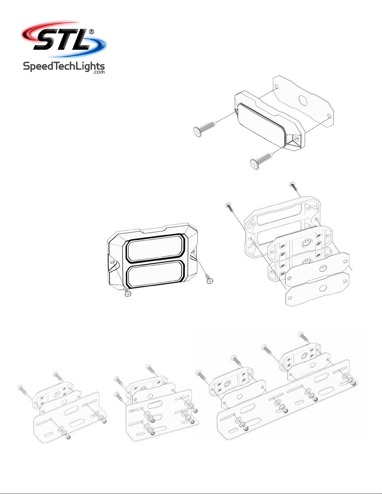
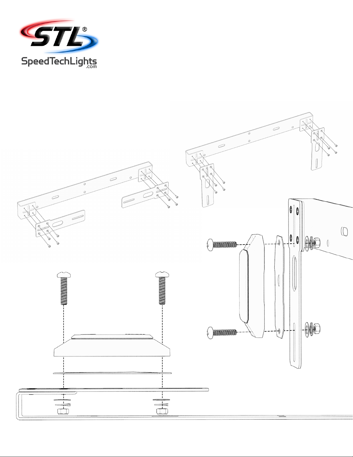
GRILLE / SURFACE MOUNT
Warnings and Notices for Users and Installers
This document must be delivered to and read by the end user and installer as it serves to provide you with the required information for proper and
safe use of your STL product. Before operating this or any STL products the user and installer must read this manual all the way through. You will nd
important information in this manual that could prevent property damage and/or serious injury to the user and installer.
STL products are intended to alert pedestrians and other operators of the presence of personnel, the operation of emergency vehicles, an emergency
site, and any warning needs. This does not ensure that pedestrians or drivers will react, heed, or observe emergency warning signals. Nor does the use
of emergency signals grant or ensure you the right of way. It is your responsibility to make sure you can proceed safely before driving against trac,
entering an intersection, responding at a high rate of speed, or walking on or around trac lanes.
Your STL emergency vehicle devices should be tested daily to ensure the device and all its functions are operating correctly. If you experience a
malfunction contact STL’s Customer Service immediately for troubleshooting options, or a warranty or service claim. You must ensure that the projection
of the visual and audible signal is not blocked by vehicle components (i.e.: open trunks, visors, compartment doors), vehicles, other obstructions, or
people.
This is professional grade equipment and is intended for strict use by authorized personnel only. It is the user’s responsibility to understand and obey all
laws regarding emergency warning devices. You must know and be familiar with all applicable city, state, and federal laws and regulations prior to the
use of emergency vehicle warning devices.
SpeedTech Lights, Inc assumes no liability for any loss resulting from the use of this warning device. Proper installation is vital to the performance of the
warning devices and safe operation of the emergency vehicle. Since the operator is under stressful environments the equipment must be properly wired
and mounted to ensure eectiveness and safety. Therefore controllers must be properly installed and placed within convenient reach of the operator so
eye contact with the roadway is never lost.
The eectiveness of your STL equipment is highly dependent upon correct mounting and wiring. Improper wiring and mounting of the warning device will
reduce the output and performance of the equipment. Emergency warning devices frequently require high electrical voltages and/or currents. Properly
protect and use caution around live electrical connections. Grounding or shorting of electrical connections can cause high current arcing, which can
cause severe personal injury and/or serious vehicle damage, including re.
Electromagnetic interference can be caused by many electronic devices used in emergency vehicles. To ensure that this doesn’t happen to you, Light
Bars should be mounted a minimum of 12” - 34” from the radio antenna and do not power your equipment from the same circuit or share the same
grounding circuit with radio communication equipment. After installation, test all the vehicle’s equipment together to ensure everything operates free of
interference.
Driver and/or passenger airbags (SRS) will impact the way you mount your equipment. Any equipment installed in the deployment area of the airbags
will damage or dislodge the airbags and sensors. This will also reduce the eectiveness of the airbags to protect the passengers and therefore these
areas must be avoided. Installers must make sure that this equipment along with any parts, hardware, wiring, power supplies, and switch boxes do not
interfere with the airbags, SRS wiring, or sensors.
All STL equipment needs to be mounted and installed according to the vehicle manufacturer’s instructions and securely attached to a part of the vehicle
of sucient strength to withstand the forces applied by the equipment. This device should be permanently mounted within the zones specied by the
vehicle manufacturer. This especially applies to equipment mounted on the exterior of the vehicle to avoid dislodging. Mounting units on the interior of
the vehicle by a method other than permanent mount is discouraged as it may become detached under aggressive driving conditions such as sudden
braking, collision, or swerving.
PROPER INSTALLATION COMBINED WITH OPERATOR TRAINING IN THE PROPER USE OF EMERGENCY WARNING DEVICES IS ESSENTIAL
TO ENSURE THE SAFETY OF EMERGENCY PERSONNEL AND THE PUBLIC.
Unpacking Your STL Product
• Unpack your unit to identify all parts including but not limited to: Light Bar, switch box, brackets, screws, bolts, wiring harness, fuses, etc.
• Some parts may be in small bags.
• Some products may be packaged inside boxes of other products.
• Some parts such as Gutter Brackets, may be in the foam protection. Double check that no parts are left within the foam protection or left in the box.