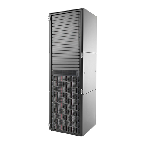
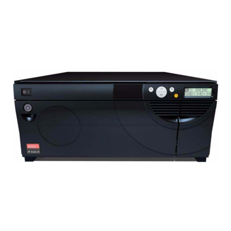
StorageWorks RA7000 User manual

RA7000 and ESA10000
Storage Subsystems
User's Guide
EK–SMCPP–UG. A01
Digital Equipment Corporation
Maynard, Massachusetts

First Edition, July 1997
The information in this document is subject to change without notice and should not be
construed as a commitment by Digital Equipment Corporation. Digital Equipment
Corporation assumes no responsibility for any errors that may appear in this document.
Restricted Rights: Use, duplication, or disclosure by the U.S. Government is subject to
restrictions as set forth in subparagraph (c) (1) (ii) of the Rights in Technical Data and
Computer Software clause at DFARS 252.227-7013.
Digital Equipment Corporation does not give a warranty of any kind regarding the
fitness or applicability of the information content for a particular purpose. The user
assumes all responsibility for understanding the interrelationships of this enclosed
information with other affected software or system products.
The disclosure of this information does not grant to the user a license under any patents,
pending patents, trademarks, or copyrights or other rights of Digital Equipment
Corporation, or of any third party.
FCC Notice: This equipment generates, uses, and may emit radio frequency energy.
The equipment has been type tested and found to comply with the limits for a Class A
computing device pursuant to Subpart J of Part 15 of FCC Rules, which are designed to
provide reasonable protection against such radio frequency interference when operated
in a commercial environment. Any changes or modifications made to this equipment
may void the user's authority to operate the equipment. Operation of this equipment in a
residential area may cause interference, in which case the user, at his own expense, may
be required to take measures to correct the interference.
UNIX is a registered trademark in the United States and other countries, licensed
exclusively through X/Open Company, Ltd.
Microsoft is a registered trademark and Windows and Windows NT are trademarks of
Microsoft Corporation.
All other trademarks and registered trademarks are the property of their respective
owners.
DIGITAL, the DIGITAL logo, and StorageWorks are trademarks of Digital Equipment
Corporation.
Copyright © Digital Equipment Corporation 1997 All Rights Reserved
Printed in U. S. A

EK–SMCPP–UG. A01 iii
Contents
Revision Record ........................................................................................................ ix
About This Guide ...................................................................................................... xi
1 Product Description
1.1 Subsystem Overview................................................................................................. 1–1
1.2 Major Components.................................................................................................... 1–4
1.2.1 HSZ70 RAID Array Controllers............................................................................. 1–5
1.2.2 SCSI Buses............................................................................................................ 1–6
1.2.3 Single-Ended I/O Module (SE I/O)........................................................................ 1–7
1.2.3.1 Expanding the UltraSCSI Bus.............................................................................. 1–8
1.2.3.2 Controlling the Internal SCSI Bus....................................................................... 1–9
1.2.3.3 Controlling the External SCSI Bus...................................................................... 1–9
1.2.3.4 Controlling the Fault Bus.................................................................................... 1–9
1.2.3.5 “Warm Swapping” I/O Modules and Cables ....................................................... 1–9
1.3 Error Detection and Reporting................................................................................. 1–10
1.3.1 Fault Bus............................................................................................................. 1–10
1.3.2 Environmental Monitor Unit (EMU).................................................................... 1–11
1.3.2.1 Controller Status............................................................................................... 1–11
1.3.2.2 I/O Module Status............................................................................................. 1–12
1.3.2.3 Enclosure Configuration Information................................................................ 1–12
1.3.2.4 EMU Front Panel.............................................................................................. 1–13
1.3.3 Power Verification and Addressing (PVA) Module.............................................. 1–15
1.3.3.1 Monitoring Power Supply Operation................................................................. 1–16
1.3.3.2 Master Enclosure Controlled Power Shutdown ................................................. 1–17
1.3.3.3 Expansion Enclosure Initiated Power Shutdown................................................ 1–18
1.3.3.4 PVA UPS (Uninterruptable Power Supply) Options.......................................... 1–19
1.4 Storage Device SBBs............................................................................................... 1–19
1.5 Power Configuration................................................................................................ 1–20
1.5.1 AC Power Entry Controllers................................................................................ 1–20
1.6 Power Supply SBBs................................................................................................. 1–22
1.7 Standard (4 + 1) Power Configuration ..................................................................... 1–23
1.8 Redundant (4 + 4) Power Configuration................................................................... 1–25
1.9 ECB SBBs............................................................................................................... 1–26

RA7000 nd ESA10000 Storage Subsystems
iv EK–SMCPP–UG. A01
1 Product Description (continued)
1.10 Subsystem Cooling................................................................................................ 1–28
1.11 Setting the PVA SCSI Address.............................................................................. 1–30
1.11.1 DIGITAL Supported Master PVA Address........................................................ 1–31
1.11.2 DIGITAL Supported Expansion PVA Addresses................................................ 1–32
1.11.3 Non-Supported PVA SCSI Bus Addresses ......................................................... 1–32
2 Unpacking and Installation for the RA7000 and ESA10000 Storage Subsystems
2.1 Installing the RA7000................................................................................................ 2–1
2.1.1 Site Preparation..................................................................................................... 2–2
2.1.2 Unpacking the RA7000 Subsystem Enclosure........................................................ 2–2
2.1.3 Removing the RA7000 from the Pallet .................................................................. 2–3
2.1.4 Placing the RA7000 Storage Enclosure.................................................................. 2–5
2.1.5 Connecting the Enclosure to the Host .................................................................... 2–5
2.2 Installing the ESA10000............................................................................................ 2–6
2.2.1 Site Preparation..................................................................................................... 2–6
2.2.2 Unpacking the ESA10000 Subsystem Enclosure.................................................... 2–7
2.2.3 Removing the ESA10000 from the Pallet............................................................... 2–9
2.2.4 Moving the ESA10000 to It’s Designated Site..................................................... 2–13
2.2.5 Joining Adjacent ESA10000’s ............................................................................. 2–13
2.2.6 Leveling the Cabinet............................................................................................ 2–16
2.3 Installing Additional Components ........................................................................... 2–16
2.3.1 Installing the BA370 Rack-Mountable Enclosure................................................. 2–16
2.4 Cabling a Master Enclosure to an Expansion Enclosure(s)....................................... 2–24
2.4.1 Cabling Sequence................................................................................................ 2–24
2.4.2 Attaching the SE I/O Cables................................................................................ 2–24
2.4.2.1 Single Expansion Unit...................................................................................... 2–25
2.4.2.2 Two Expansion Units........................................................................................ 2–26
2.4.3 Attaching the EMU Communications Cable......................................................... 2–27
2.4.4 Setting the PVA Addresses.................................................................................. 2–28
2.5 Connecting SCSI Bus Cables to the ESA10000........................................................ 2–30
2.6 Installing SBBs........................................................................................................ 2–32
2.6.1 Installing SBB Disk Drives.................................................................................. 2–32
2.6.2 Installing SBB Power Supplies............................................................................ 2–34
2.6.3 Installing the AC Input Power Controller............................................................. 2–35
2.6.4 Installing the External Cache Battery (ECB)........................................................ 2–36
3 Configuring the Storage Cabinet
3.1 Configuring the EMU................................................................................................ 3–1
3.1.1 Connecting the EMU Communications Bus........................................................... 3–2
3.1.2 Setting the Temperature Sensors............................................................................ 3–2
3.1.3 Setting the Blower Speed Control.......................................................................... 3–3
3.1.4 Alarm Control Switch............................................................................................ 3–4

Contents
EK–SMCPP–UG. A01 v
4 Error Analysis and Fault Isolation
4.1 Storage Subsystem Error Reporting........................................................................... 4–1
4.2 EMU Error and Fault Status Reporting...................................................................... 4–4
4.3 EMU Subsystem Status LEDs.................................................................................... 4–5
4.3.1 EMU System Fault Code Displays......................................................................... 4–8
4.3.2 Controlled Power Shut Down............................................................................... 4–13
4.3.3 Automatic Shut Down ......................................................................................... 4–13
4.3.4 User-Initiated Master Enclosure Shut Down ........................................................ 4–14
4.3.5 User-Initiated Expansion Enclosure Shut Down................................................... 4–15
4.4 Controller Error Conditions..................................................................................... 4–16
4.5 Storage Device Fault Notification............................................................................ 4–16
4.6 Power Supply Fault Notification.............................................................................. 4–18
4.7 I/O Module Error Reporting .................................................................................... 4–19
4.7.1 Incompatible I/O Modules................................................................................... 4–19
4.7.2 No I/O Module Installed...................................................................................... 4–19
4.7.3 TERMPOWER Errors.......................................................................................... 4–19
5 Replacing Components
5.1 Replacing a Controller or Cache Module................................................................... 5–1
5.1.1 Tools Required...................................................................................................... 5–1
5.1.2 Precautions............................................................................................................ 5–1
5.2 Preparing Your Host System...................................................................................... 5–2
5.2.1 Backup the System................................................................................................ 5–2
5.2.2 Shut Down the System........................................................................................... 5–2
5.3 Controller Module Removal...................................................................................... 5–2
5.4 Cache Module Removal............................................................................................. 5–5
5.5 Replacing an SBB Storage Device............................................................................. 5–6
5.5.1 Replacement Method............................................................................................. 5–7
5.5.2 Before You Replace a Storage SBB....................................................................... 5–7
5.5.3 SBB Replacement.................................................................................................. 5–7
5.6 Replacing Storage Subsystem Blowers...................................................................... 5–9
5.7 Replacing a Power Supply SBB............................................................................... 5–11
5.8 Replacing a Power Entry Controller......................................................................... 5–12
5.9 Replacing an EMU.................................................................................................. 5–13
5.10 Replacing a PVA................................................................................................... 5–14
5.11 FRU Parts List....................................................................................................... 5–15
Reader Comment Form ...................................................................Inside Back Cover

RA7000 nd ESA10000 Storage Subsystems
vi EK–SMCPP–UG. A01
Figures
Figure 1–1 BA370 Rack Mountable Enclosure............................................................... 1–1
Figure 1–2 RAID 7000 Enclosure................................................................................... 1–2
Figure 1–3A ESA10000 Storage Cabinet (Shown with two BA370 Rack Mountable
Enclosures in one cabinet)...................................................................................... 1–2
Figure 1–3B ESA10000 Storage Cabinet (Shown with three BA370 Rack Mountable
Enclosures in two cabinets).................................................................................... 1–3
Figure 1–4 Configured BA370 Rack Mountable Unit Major Components....................... 1–4
Figure 1–5 HSZ70 Controller and Cache Modules.......................................................... 1–5
Figure 1–6 SCSI Buses................................................................................................... 1–6
Figure 1–7 Single-Ended I/O Module Location .............................................................. 1–7
Figure 1–8 Single-Ended I/O Module............................................................................. 1–8
Figure 1–9 Environmental Monitor Unit (EMU)........................................................... 1–13
Figure 1–10 Power Verification and Addressing (PVA) Module................................... 1–15
Figure 1–11 Disk Drive SBB........................................................................................ 1–19
Figure 1–12 AC Power Entry Controller....................................................................... 1–21
Figure 1–13 Typical Shelf Power Supply SBB.............................................................. 1–22
Figure 1–14 Standard Power Configuration (4 + 1)....................................................... 1–24
Figure 1–15 Redundant Power Configuration (4 + 4).................................................... 1–25
Figure 1–16 External Cache Battery (ECB) SBB.......................................................... 1–26
Figure 1–17 Cache-to ECB-Connection........................................................................ 1–28
Figure 1–18 Dual Speed Blower Locations................................................................... 1–29
Figure 1–19 Enclosure SCSI Address Switch................................................................ 1–30
Figure 1–20 Enclosure SCSI Bus Addresses for all SBB Device IDs............................ 1–31
Figure 2–1 RA7000 Minimum Installation Clearance Measurements.............................. 2–1
Figure 2–2 Unpacking the RA7000 Storage Enclosure.................................................... 2–3
Figure 2–3 Installation of Ramp on Shipping Pallet........................................................ 2–4
Figure 2–4 Minimum Installation Clearance Measurements ........................................... 2–6
Figure 2–5 Shipping Container Contents ........................................................................ 2–7
Figure 2–6 Shipping Pallet Ramp Installation............................................................... 2–10
Figure 2–7 Shipping Bolts and Brackets....................................................................... 2–11
Figure 2–8 Removing the Cabinet from the Pallet ....................................................... 2–12
Figure 2–9 Leveler Foot Adjustment............................................................................ 2–16
Figure 2–10 Mounting Rail Orientation........................................................................ 2–18
Figure 2–11 Rail Installation into Cabinet.................................................................... 2–19

Contents
EK–SMCPP–UG. A01 vii
Figures (continued)
Figure 2–12 ECB Position............................................................................................ 2–20
Figure 2–13 Installing ECB Y-Cables........................................................................... 2–20
Figure 2–14 Attaching Mounting Brackets to the BA370.............................................. 2–21
Figure 2–15 SE I/O Port Identification......................................................................... 2–24
Figure 2–16 SE I/O Port Wiring (One Expansion Unit) ................................................ 2–25
Figure 2–17 SE I/O Connections for Two Expansion Units........................................... 2–26
Figure 2–18 EMU Front Panel...................................................................................... 2–27
Figure 2–19 Multiple EMUs Connected Together......................................................... 2–27
Figure 2–20 PVA Module Front Panel.......................................................................... 2–28
Figure 2–21 Expansion Enclosure SCSI Bus Addresses................................................ 2–29
Figure 2–22 SCSI Bus Cabling for the ESA10000........................................................ 2–31
Figure 2-23 Installing Power Supply SBB (4+4 Shown) ............................................... 2–34
Figure 2–24 Installing the External Cache Batteries ..................................................... 2–36
Figure 4–1 Storage Subsystem Status LEDs ................................................................... 4–2
Figure 4–2 EMU Front Panel Layout.............................................................................. 4–4
Figure 4–3 Typical Controller OCP Display................................................................. 4–16
Figure 4–4 Storage SBB LEDs..................................................................................... 4–17
Figure 4–5 Power Supply SBB Status LEDs................................................................. 4–18
Figure 4–6 I/O Module LEDs....................................................................................... 4–20
Figure 5–1 HSZ70 Controllers and Cache Modules........................................................ 5–3
Figure 5–2 Trilink Connector......................................................................................... 5–4
Figure 5–3 Cache Module Replacement ......................................................................... 5–5
Figure 5–4 SBB Identification Label.............................................................................. 5–6
Figure 5–5 SBB Replacement......................................................................................... 5–9
Figure 5–6 Blower Replacement................................................................................... 5–10
Figure 5–7 Power Supply SBB Replacement................................................................ 5–11
Figure 5–8 Power Entry Controller Replacement......................................................... 5–12
Figure 5–9 EMU Module Replacement......................................................................... 5–13
Figure 5–10 PVA Module Replacement....................................................................... 5–14
Figure 5–11 Storage Cabinet Field Replaceable Parts (RA7000 Shown)....................... 5–16

RA7000 nd ESA10000 Storage Subsystems
viii EK–SMCPP–UG. A01
Tables
Table 1–2 EMU Front Panel Component Descriptions.................................................. 1–14
Table 1–2 Storage Subsystem Major Power Components ............................................. 1–20
Table 1–3 ECB Status Indications ................................................................................ 1–27
Table 1–4 Expansion Enclosure Address Combinations............................................... 1–32
Table 2–2 Installing Rails for the Upper BA370........................................................... 2–18
Table 2–3 Installing Rails for the Lower BA370........................................................... 2–18
Table 2–5 Expansion Enclosure Address Combinations............................................... 2–28
Table 3–1 EMU Set Point Temperatures......................................................................... 3–3
Table 4–1 Subsystem Status LEDs .................................................................................. 4–3
Table 4–2 EMU Subsystem Status LEDs........................................................................ 4–5
Table 4–3 EMU LED Displays....................................................................................... 4–6
Table 4–4 EMU Fault Code LED Displays..................................................................... 4–9
Table 4–5 Storage SBB Status LED Displays................................................................. 4–7
Table 4–6 Power Supply SBB Status LED Displays ..................................................... 4–18
Table 5–1 RAID Controller Response to an SBB Replacement....................................... 5–8
Table 5–2 Subsystem Field Replaceable Units.............................................................. 5–15

EK–SMCPP–UG. A01 ix
Revision Record
This Revision Record provides a concise publication history of this guide. It lists the
manual revision levels, release dates, and summary of changes.
The following revision history lists all revisions of this publication and their effective
dates. The publication part number is included in the Revision Level column, with the
last entry denoting the latest revision.
Revision Level Date Summary of Changes
EK–SMCPP–UG. A01 July 1997 Initial release


EK–SMCPP–UG. A01 xi
About This Guide
This section identifies the users of this guide and describes the contents and structure. In
addition, it includes a list of conventions used in this guide and related documentation.
RA7000 and ESA10000 Storage Subsystems User's Guide
This guide provides a product description, set up, configuration, and maintenance
information for the RAID Array 7000 (RA7000) and the Enterprise Storage
Array 10000 (ESA10000) Storage Subsystems.
Visit Our Web Site for the Latest Information
Check our web for the latest drivers , technical tips, and documentation. We can
be found in the technical area of our web page, http://www.storage.digital.com/
Intended Audience
This guide is intended for users who are responsible for installing, configuring,
and repairing the RA7000 and ESA10000 Storage Subsystems.
Document Structure
This guide contains the following chapters:
Chapter 1: Product Description
Product Description provides a product overview of the RA7000 and
ESA10000 Storage Subsystems. It also describes their components, features, and
operating functions.
Chapter 2: Unpacking and Installation
Unpacking and Installation describes how to unpack and install the subsystem.
Chapter 3: Configuring the Storage cabinet
Configuring the Storage Cabinet describes how to connect the EMU
communications bus and setting monitoring controls.

RA7000 and ESA10000 Storage Subsystems
xii EK–SMCPP–UG. A01
Chapter 4: Error Analysis and Fault Isolation
Error Analysis and Fault Isolation describes the errors, faults, and significant
events that may occur during the enclosure's initialization and operation.
Chapter 5: Replacing Components
Replacing Components describes the procedures to remove and install the Field
Replaceable Units (FRUs) in the subsystem.
Conventions
This guide uses the following conventions:
Style Meaning
boldface type For emphasis and user input.
italic type
For emphasis, manual titles, utilities, menus,
screens, and filenames
plain monospace type Screen text.
Related Documentation
For additional information on the RAID controller, refer to the following
StorageWorks documents:
Document Title Document Part Number
CLI Reference Manual EK-CLI70-RM
Configuration Manual EK-HSZ70-CG
Service Manual EK-HSZ70-SV

EK–SMCPP–UG. A01 1–1
1
Product Description
This chapter describes the RA7000 and ESA10000 Storage Subsystems including the
Ultra Small Computer System Interface (SCSI-3) connections (ports) for StorageWorks
building block (SBB) shelves.
1.1 Subsystem Overview
The RA7000 and ESA10000 Storage Subsystems are members of DIGITAL’s
StorageWorks family of modular enclosures. They share a common major
component, the BA370 Rack Mountable Enclosure (Figure 1-1), that includes an
Environmental Monitor Unit (EMU) and a Power Verification and Addressing
(PVA) module. StorageWorks storage devices, power supplies, controller(s),
cache module(s), External Cache Battery (ECB),and power entry controllers may
also be included. Figures 1-2, 1-3A, and 1-3B show three possible BA370
configurations.
Figure 1–1 BA370 Rack Mountable Enclosure
CXO5797A

RA7000 and ESA10000 Storage Subsystems
1–2 EK–SMCPP–UG. A01
Figure 1–2 RAID 7000 Enclosure
Figure 1–3A ESA10000 Storage Cabinet (Shown with two BA370 Rack
Mountable Enclosures in a sngle cabinet)
1
0
0
1
0
CXO5828A

Chapter 1. Product Description
EK–SMCPP–UG. A01 1–3
Figure 1–3B ESA10000 Storage Cabinet (Shown with three BA370 Rack
Mountable Enclosures in two cabinets)
CXO5845A
1
0
0
1
0
0
1
0
The major features of the BA370 rack mountable enclosure are as follows:
• StorageWorks compatible
• Holds up to twenty-four 3½-inch disk drive SBBs per BA370
• Redundant power distribution to eliminate single points of failure
• Contains six, single-ended, Ultra Wide SBB backplane SCSI buses
• No internal SCSI bus cables
• A StorageWorks HSZ70 RAID array controller that is compatible with the
approved host computer SCSI bus adapters
• Redundant ac power entry controllers
• All major components, except the single ended I/O modules and PVA
module, can be replaced using the hot-swap method described in Chapter 5.
• Fault monitoring and reporting capability for incorrect voltages, shelf
blower failure, power supply failure, and excessive operating temperature.
• The BA370 may be used as a master or an expansion unit
NOTE
The master unit contains the controller(s) and
cache module(s). Expansion units contain
additional storage devices on the same SCSI
buses.
• The 24-SBB RAID Array 7000 storage subsystem and the ESA10000
storage subsystem are Class A FCC certified.

RA7000 and ESA10000 Storage Subsystems
1–4 EK–SMCPP–UG. A01
1.2 Major Components
A fully configured redundant subsystem (Figure 1-4) consists of the following
major components:
1) A BA370 Rack mountable enclosure (1)
2) Dual-Speed Blowers (8)
3) Single-Ended I/O Modules (6)
4) Power Verification and Addressing (PVA) Module (1)
5) AC Input Power Controllers (2)
6) Cache Modules (2)
7) HSZ70 SCSI RAID Array Controllers (2)
8) Environmental Monitor Unit (EMU) (1)
9) SBB Power Supplies (8)
10) External Cache Batteries (2)
also:
11) Power Distribution Unit (2) Not shown, mounted in ESA10000 cabinet only
Figure 1–4 Configured BA370 Rack Mountable Unit Major Components
CXO5803A
1
2
3
5
6
7
8
9
10
4

Chapter 1. Product Description
EK–SMCPP–UG. A01 1–5
1.2.1 HSZ70 RAID Array Controllers
The controller connects a host system to the subsystem and appears as another
SCSI device connected to one of its I/O buses. The controller then processes the
I/O requests to the storage devices of the subsystem. The HSZ70 RAID array
controller(s) mount in the lower front of the cabinet (see Figure 1-5). Installing
two HSZ70 controllers with cache modules provides complete controller
redundancy as described in the HSZ70 Service Manual.
Figure 1–5 HSZ70 Controller and Cache Modules
NOTE
Controllers and Cache modules removed from
controller card cage for clarity. Modules are not a
single unit.
The controller documentation describes procedures for:
• Configuring the controller
• Setting initial controller parameters using a maintenance terminal
• Determining the proper method for replacing SBBs (hot-swap)
The controller software revision level determines the devices supported by the
controller.

RA7000 and ESA10000 Storage Subsystems
1–6 EK–SMCPP–UG. A01
1.2.2 SCSI Buses
There are six Ultra Wide SCSI buses associated with the controller. The ports
and device addresses for the master unit are shown in Figure 1-6.
Figure 1–6 SCSI Buses

Chapter 1. Product Description
EK–SMCPP–UG. A01 1–7
The subsystem enclosure supports single-ended, Ultra Wide storage devices. The
configuration rules for the SCSI buses are as follows:
• All devices and ports in the same column are on the same SCSI bus or port
• All devices in the same row (device shelf) have the same device address
• You may only install controller-compatible Ultra Wide storage SBBs
• Device addresses 4 and 5 are only used when the SBB has a device address
switch
• Device addresses are determined by the backplane connector into which the
device is inserted unless the SBB has a device address switch
1.2.3 Single-Ended I/O Module (SE I/O)
Figure 1–7 Single-Ended I/O Module Location

RA7000 and ESA10000 Storage Subsystems
1–8 EK–SMCPP–UG. A01
Each SCSI enclosure, whether it is a master or an expansion enclosure, has six
I/O modules mounted at the bottom rear of the enclosure as shown in Figure 1-7.
In all enclosures these modules are the interconnection point between the
controller in the master enclosure and the devices in the expansion enclosures. In
an UltraSCSI RAID subsystem, the I/O modules, the internal SCSI buses, and the
controller ports all have the same number. For example, controller port 2, SCSI
bus 2, and I/O module 2 are different elements of the same bus. The major
features of the single-ended I/O module are described in the following sections.
1.2.3.1 Expanding the UltraSCSI Bus
Each I/O module has an UltraSCSI single-ended bus expansion integrated circuit.
This device isolates the internal and external SCSI bus and extends the length of
the SCSI bus.
Figure 1–8 Single-Ended I/O Module
CXO5947A
External
TERM POWER
disable LED
Internal
TERM POWER
disable LED
The two VHDCI female connectors are the connection points for expanding the
SCSI buses between enclosures (see Figure 1-8). These connectors are wired in
parallel and act as a tri-link connector. In an expansion configuration, DIGITAL
recommends that maximum cable length not exceed 1.5 m (4.6 ft.) between
enclosures. DIGITAL supplies a cable kit, DS-BNK37-IE, containing the
necessary cables to connect an expansion unit.
This manual suits for next models
1
Table of contents
Other StorageWorks Storage manuals
