Storehouse 92970 User manual
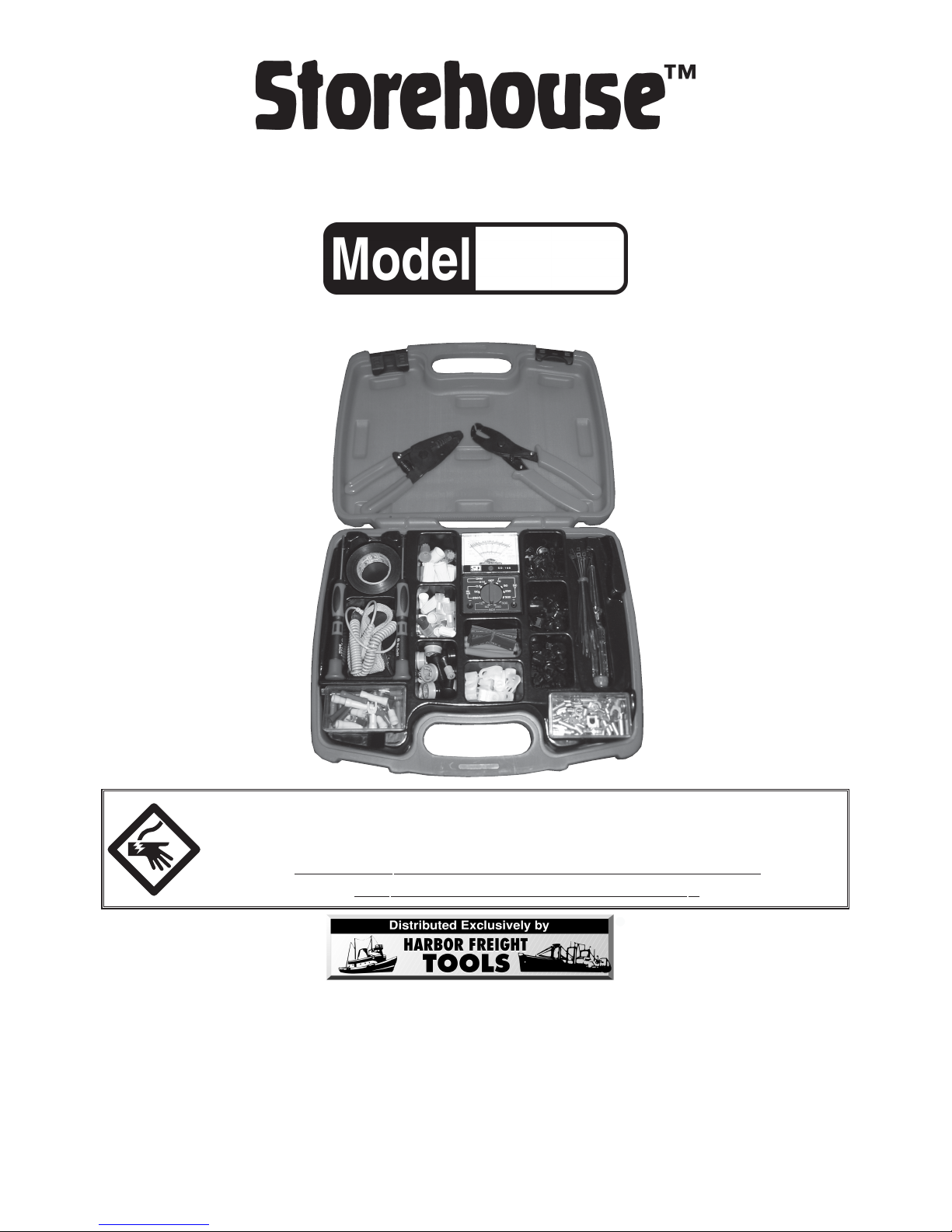
269 PC. ELECTRICAL REP269 PC. ELECTRICAL REP
269 PC. ELECTRICAL REP269 PC. ELECTRICAL REP
269 PC. ELECTRICAL REPAIR KITAIR KIT
AIR KITAIR KIT
AIR KIT
OPERATING INSTRUCTIONS
3491 Mission Oaks Blvd., Camarillo, CA 93011
Visit our Web site at http://www.harborfreight.com
Copyright©2005 by Harbor Freight Tools®. All rights reserved. No portion
of this manual or any artwork contained herein may be reproduced in any
shape or form without the express written consent of Harbor Freight Tools.
For technical questions and replacement parts, please call 1-800-444-3353
®
92970
WARNING!
Electric shock can cause DEATH or SEVERE PERSONAL INJURY.
Never touch exposed conductors of electricity with
fingers, hands or any other body part.

SKU 92970 Page 2For technical questions, please call 1-800-444-3353.
Save This Manual
You will need the manual for the safety warnings and precautions, and
operating and maintenance procedures. Keep your invoice with this manual. Write
the invoice number on the inside of the front cover. Keep the manual and invoice in
a safe and dry place for future reference.
Safety Warnings and Precautions
WARNING: When using tool, basic safety precautions should always be followed to
reduce the risk of personal injury and damage to equipment.
Read all instructions before using this kit!
If all warnings and safety precautions in this manual are not followed
completely, the protection provided by these products will be reduced.
In this manual:
WARNING indicates a potentially hazardous situation which, if not avoided,
could result in death or serious personal injury.
CAUTION indicates a potentially hazardous situation which, if not avoided,
may result in a minor/moderate personal injury or damage to this tool or the unit
being tested by it.
Multimeter Specifications
METINOITPIRCSEDMETINOITPIRCSED
segnaRegatloVCAV005/052/05/01 serutaeFrehtO dnatsujdAoreZ
oreZ ΩtsujdA
segnaRegatloVCDV005/052/05/01
segnaReg
arepmACDAm052/05/5.0yalpsiDgolanA
egnaRecnatsiseRK1x ΩyrettaBepyT"AA"V5.1
ssalCycaruccA5.2erutarepmeTgnitarepOF°
131ot°41
Electrical Tape Specifications
METINOITPIRCSEDMETINOITPIRCSED
nwodkaerBcirtceleiDV0007htdiW
3
/
4
"
htgneL'03ssenkcihT)"700.(lim7

SKU 92970 Page 3For technical questions, please call 1-800-444-3353.
WARNING
1. Avoid working alone. If an accident happens, an assistant can bring help.
2. Keep work area clean. Cluttered areas invite injuries.
3. Avoid electrical shock. Use extreme caution when working around uninsu-
lated conductors or bus bars. Prevent body contact with grounded surfaces
such as pipes, radiators, ranges, and cabinet enclosures when testing volt-
ages.
4. Avoid damaging meter. Use only as specified in this manual.
5. Observe work area conditions. Do not test circuits in damp or wet locations.
Don’t expose to rain. Keep work area well lit.
6. Keep children away. Children must never be allowed in the work area. Do not
let them handle machines, tools, or extensions cords. Small parts within this
kit can be choked upon or swallowed by small children.
7. Store idle equipment. When not in use, tools must be stored in a dry location
to inhibit rust. Always store all parts in the case and keep out of reach of
children.
8. Dress properly. Do not wear jewelry as an accidental brush may cause a
short circuit, resulting in electric shock or severe burns. Protective, electrically
nonconductive clothes and nonskid rubber-soled footwear are recommended
when working. Wear restrictive hair covering to contain long hair.
9. Use eye protection. Always wear ANSI approved impact safety goggles.
10. Do not overreach. Keep proper footing and balance at all times. Do not reach
over or across electrical cables or frames.
11. Maintain tools with care. Ensure multimeter has a fresh battery. Keep all
insulation clean and dry; moisture or contaminants can conduct electricity and
present a hazard.
12. Stay alert. Watch what you are doing, use common sense. Do not operate
any tool when you are tired.
13. Check for damaged parts. Before using any tool, any part that appears dam-
aged should be carefully checked to determine that it will operate properly and
perform its intended function. Check for alignment and binding of moving parts;
any broken parts or mounting fixtures; and any other condition that may affect
proper operation. In addition to a general inspection, look specifically for:
a. Pay special attention to the insulation protecting the connectors.
b. Check the leads for exposed metal, damaged insulation, and continu-
ity. Replace damaged test leads immediately, before use.
Any part that is damaged should be properly repaired or replaced by a quali-
fied technician. Do not use the tool if any switch does not operate properly.

SKU 92970 Page 4For technical questions, please call 1-800-444-3353.
14. Remove the Test Leads (14) and switch the Multimeter (14) to OFF before
performing maintenance or opening the meter’s case.
15. Do not use the Multimeter (14) if:
a. The test leads are damaged in any way.
b. The battery is low.
c. Near any explosive gasses or fumes.
d. Any abnormal operation is detected.
(If in doubt about the condition of the meter, have it serviced.)
e. The cover is open.
16. The Meter (14) should be powered only by a correctly installed 1.5V “AA”
type battery.
17. Accessories. Only use accessories intended for use with this tool. Approved
accessories are available from Harbor Freight Tools.
18. Do not operate tool if under the influence of alcohol or drugs. Read warn-
ing labels on prescriptions to determine if your judgment or reflexes are impaired
while taking drugs. If there is any doubt, do not operate the tool.
19. People with pacemakers should consult their physician(s) before using
this product. Electromagnetic fields in close proximity to a heart pacemaker
could cause interference to or failure of the pacemaker.
20. Do not test voltage on circuits higher than 500 volts. Do not test current
on DC circuits higher than .5 amps or on AC circuits at all.
21. The included Anti-static Wrist Strap (5) is intended solely to help mini-
mize static shock damage to sensitive electronics. THE WRIST STRAP IS
NOT DESIGNED TO PROTECT THE USER FROM ELECTRIC SHOCK.
22. Never apply flame to the heat shrink tubing. The heat shrink tubing is de-
signed specifically for use with a heat gun (not included) and may get damaged,
or allow the insulation beneath to be damaged, if a direct flame is applied.
CAUTION
1. Prior to testing capacitors, resistance, diodes, or continuity; disconnect all power
to the circuit and discharge all high-voltage capacitors.
2. Use the proper settings, terminals, techniques, and range for the tests per-
formed. Always start with the range stated in the instructions.
3. Be careful not to apply voltage to the Test Leads (15) when the meter is in an
ohms testing position. Damage can occur to the multimeter.
Warning: The warnings, cautions, and instructions discussed in this instruction
manual cannot cover all possible conditions and situations that may occur. It
must be understood by the operator that common sense and caution are fac-
tors which cannot be built into this product, but must be supplied by the operator.
SKU 92970 Page 5For technical questions, please call 1-800-444-3353.
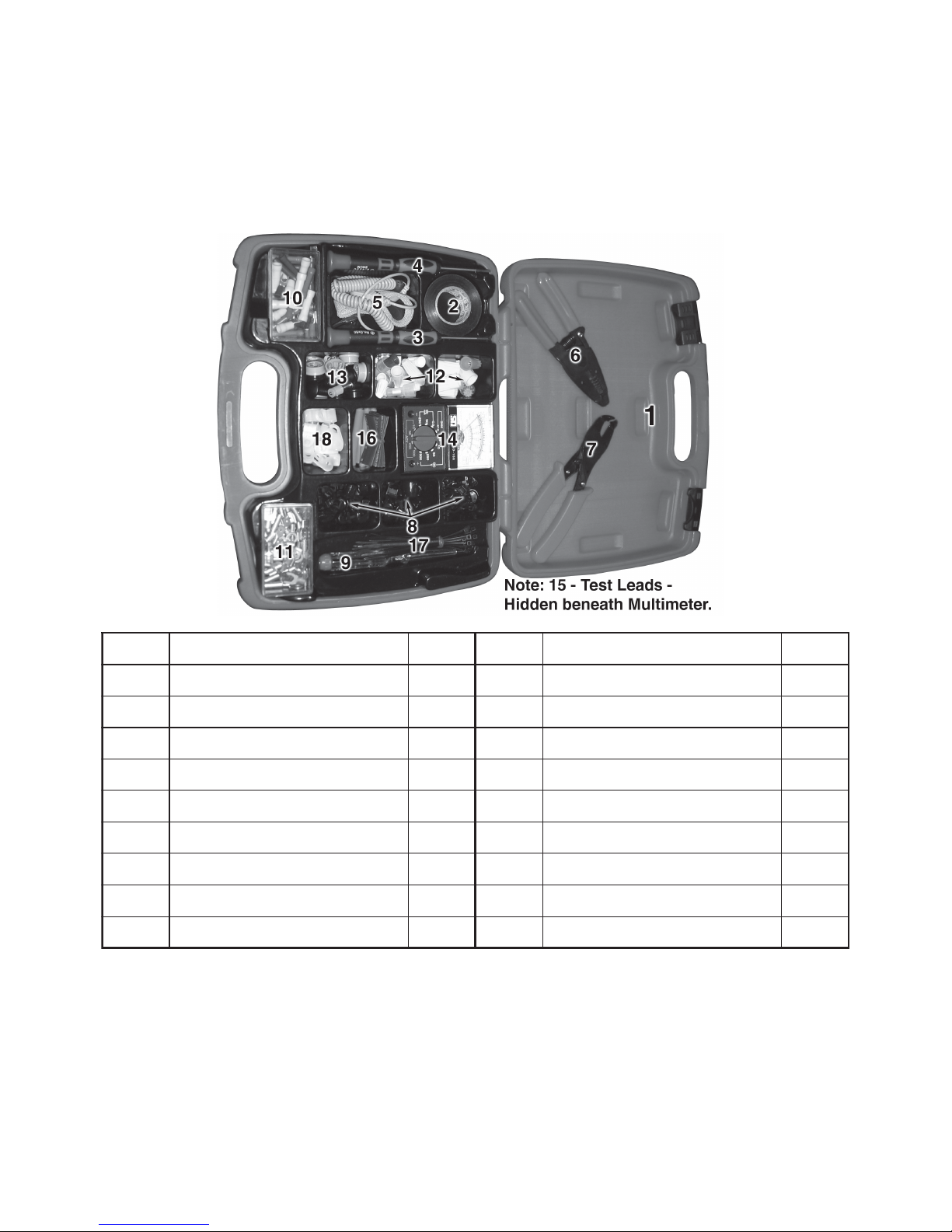
Unpacking
When unpacking, make sure that all Accessories listed below are included.
If any parts are missing or broken, please call Harbor Freight Tools at the number
on the cover of this manual.
Voltage Tester (9) instructions on page 10.
Multimeter (14) instructions on pages 6-9.
NOTE: A battery must be installed before Multimeter use.
See
Battery Replacement
under
Maintenance
, page 11.
traPnoitpircseD.tmAtraPnoitpircseD.tmA
1esaC*101slanimreTdetalusnI93
2epaTlacirtcelE'0311slanimreTdetalusni-noN05
3revir
dwercSssorC121srotcennoCeriW05
4revirdwercSdettolS131sredniBkcoL52
5partStsirWcitats-itnA141)yrettaB/w(retemitluM1
6loo
TgnipmirC151sdaeLtseT"12*teS
7rellatsnIgnihsuB161gnibuTknirhs-taeH21
8sgnihsuBfeiler-niartS5471seiTelbaC02
9retseTV052-
011181spmalCelbaC02
.tnuoclatoteceip962nidetnuoctoN*
Accessory Diagram and List
Multimeter
SKU 92970 Page 6For technical questions, please call 1-800-444-3353.
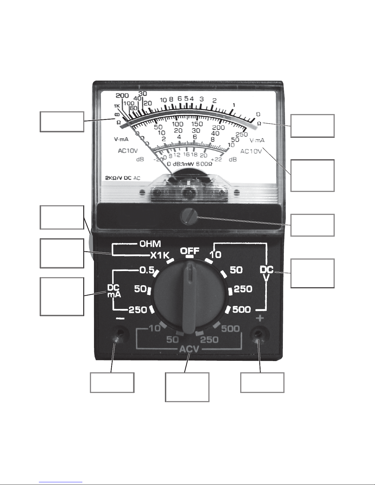
Control and Scale Layout
Refer to this diagram while following the directions in the
Operation
section.
The bold numbers inside brackets [##] below refer to the page number where the
explanation of the function starts. NOTE: Although a decibel testing function is
noted on the scale, this function is not available for this item.
The Accuracy Mirror
The Accuracy Mirror is used to insure that the meter’s pointer is being read
straight, ensuring accuracy. Simply make sure that the meter is angled so that,
when reading it, the reflection of the pointer is hidden under the pointer.
- Jack
(BLACK lead)
+ Jack
(RED lead)
DC Current
Selection
Area (mA)
[8]
AC Volt
Selection
Area [8]
Ohm Scale
[8]
Ohm
Selection
Area [8]
Ohm Zero
Adjust [8]
DC Volt
Selection
Area [7]
Accuracy
Mirror [6]
Amperage/
Voltage
Scales [7]
Zero Adjust
[9]

Multimeter
SKU 92970 Page 7For technical questions, please call 1-800-444-3353.
WARNING!
Electric shock can cause DEATH or SEVERE PERSONAL INJURY.
Always observe the following precautions when working:
1. Never touch exposed conductors of electricity with fingers, hands or
any other body part.
2. Use caution when working near voltages above 30 VAC rms, 42 VAC
peak, or 60 VDC. Voltages this high present a risk of electric shock.
3. Disconnect the circuit’s power before connecting the meter in series,
when measuring current.
4. Connect the negative (BLACK) test lead first and disconnect it last.
5. Hold the probes with fingers behind guards.
6. Whenever possible, have an assistant nearby.
Operation
DC Voltage Measurements
Measure DC voltages up to 500 V.
1. Turn the Range Selector Switch to 500 DCV.
Always start with the highest
range if the voltage is unknown.
2. Plug the red lead into the +Jack.
Plug the black lead into the -Jack.
3. Carefully touch the appropriate ex-
posed conductors with the tips of the
probes to measure the voltage (not
amperes).
4. Read measurement on the Volt/
Amp Scale - see
How to Read the
Volt/Amp Scale
table, right.
If the needle moves in the opposite
direction, then the probes are con-
nected incorrectly. Reverse the
probes’ locations.
If the voltage is less than 250 volts,
set the Range Selector Switch to the
next lower range until the meter pointer is mid-range on the scale.
5. When testing is complete, switch the meter to OFF, remove the Test Leads,
and store the leads and meter in the provided case.
elacSpmA/tloVehtdaeRotwoH
egnaRpmA/tloV elacSpmA/tloV
daeRebot reilpitluMtluseR
00505-001
052052-0–
0505-0–
0101-0–
5.005-010.0
:trahCehtesUoT
(tfe
lehtniegnardetcelesehtdniF.1 egnaR .nmuloc)
(retnecehtnidetacidnielacsehtdaeR.2 elacS )
.wortahtfonmuloc
thg
irehtnireilpitlumehtybgnidaerehtylpitluM.3
(reilpitluM "afI.wortahtfonmuloc)–ninwohssi"
eriuqertonseodgnid
aerehtneht,nmulocthgireht
.noitacilpitlum
:elpmaxE ottessiegnarehtfI VCD005 ehtneht, 05-0 elacs
ybdeipitlumdnadaerebdluow 01 .
(tnemerusaeM=reilpitluMXg
nidaeR )
fognidaerarof,oS 13 dluowtnemerusaemeht,egnarsihtni
eb VCD013 (013=01X13 .)

Multimeter
SKU 92970 Page 8For technical questions, please call 1-800-444-3353.
AC Voltage Measurements
Measure AC voltages up to 500 V.
1. Turn the Range Selector Switch to 500 ACV.
Always start with the highest range if the voltage is unknown.
2. Follow the directions on the previous page under
DC Voltage Measurements
(except for the polarity directions, they are unnecessary with AC).
DC Current Measurements
Measure DC conductors carrying up to 250 mA (.25 A).
1. Turn the Range Selector Switch to the 250 DCmA position. Plug the red lead
into the +Jack. Plug the black lead into the -Jack.
2. First, disconnect the power to the circuit to be tested. Disconnect the
ground side of the circuit and connect the meter to each disconnected end (in
series). Turn the circuit’s power on. If the pointer moves the wrong way, re-
verse the connection.
3. If the Amperage is less than 25 mA (.025 A), first disconnect power to the
circuit, set the Range Selector to the 50 DCmA range, and reconnect power.
If the Amperage is less than .25 mA, first disconnect power to the circuit,
set the Range Selector to the .5 DCmA range, and reconnect power.
4. When testing is complete, first disconnect power to the circuit, switch the
meter to OFF, remove the Test Leads, reconnect the circuit’s ground side, and
store the leads and meter in the provided case.
Resistance (Ohm) Measurements
Circuit resistance is measured at meter reading times 1,000.
Note: Testing resistance should ONLY be done with the power to the circuit
disconnected. Test to make sure no voltage is present first. If voltage is
applied while testing, disconnect the tester immediately, otherwise the
tester may be damaged.
1. Turn the Range Selector Switch to the Ohm testing position (X1K).
2. Plug the red lead into the +Jack. Plug the black lead into the -Jack.
3. Short the Test Leads together. The meter should read “0” Ohms.
4. If the meter does not read “0” Ohms, the ohmmeter needs to be calibrated to
enable accurate measurements. With the test leads held together, adjust the
Ohm Zero Adjust Knob until the meter’s pointer aligns on “0”. If this is not
possible, the battery may need to be replaced-see
Battery Replacement
un-
der
Maintenance
, page 10.
5. Touch the exposed conductors with the tips of the Test Leads. If, by chance, a
voltage is present, the meter may be damaged or destroyed. Immediately
remove the Test Leads from the conductors.

Multimeter
SKU 92970 Page 9For technical questions, please call 1-800-444-3353.
Maintenance
1. Wipe unit with a slightly damp cloth using a light detergent. Do not use sol-
vents or abrasives. Allow the unit to dry completely before use or storage.
2. Remove battery if not in use for long periods.
4. Store unit in a dry location out of children’s reach.
5. Aside from the battery, there is no user replaceable part in this unit. REPAIRS
SHOULD BE DONE ONLY BY A QUALIFIED TECHNICIAN.
6. Meter Pointer Calibration
Over time, it may become necessary to adjust the meter pointer to align on “0.”
a. Remove the Test Leads from the multimeter and make sure that the unit is
not set at an Ohm testing setting.
b. Using a small standard screwdriver, place it on the small meter Zero Ad-
just screw right below the center of the dial. See
Control and Scale Layout
on page 6.
c. Turn screw slightly until the pointer points directly at the zero Amperage/
Voltage Scale.
7. Battery Replacement
If the Ohms cannot be adjusted to indicate zero, the battery requires replacement.
a. Remove the Test Leads (15) from the multimeter and switch the multimeter
to the OFF position.
b. Turn the unit over to show its
back.
c. Remove the screw in the center
of the back cover using a cross-
head screwdriver.
d. Open the back cover.
e. Remove the battery and replace
it, being sure to align the new
battery properly. See
Figure A
.
f. Put the back cover on, then re-
tighten the screw.
Figure A
“AA” Battery
6. Read the Ohm Scale. Multiply the reading by 1,000.
7. When testing is complete, switch the meter to OFF, remove the Test Leads,
and store the leads and meter in the provided case.
Resistance (Ohm) Measurements (continued)

Voltage Tester
SKU 92970 Page 10For technical questions, please call 1-800-444-3353.
WARNING!
Electric shock can cause DEATH or SEVERE PERSONAL INJURY.
Always observe the following precautions when working:
1. Never touch exposed conductors of electricity with fingers, hands or
any other body part.
2. Use caution when working near voltages above 30 VAC rms, 42 VAC
peak, or 60 VDC. Voltages this high present a risk of electric shock.
3. This device is only intended to test live circuits. Do not rely on this
device alone to detect if a circuit is live or not. A faulty circuit, a voltage
out of this tester’s range, or an unseen failure in the device can all result in an
incorrect negative reading.
4. Hold the Tester only on the handle section. Keep fingers well away from
the metal screwdriver section.
5. Whenever possible, have an assistant nearby.
6. Never force the blade of the tester into any opening. Forcing this tool may
damage the tool and/or the electrical component being tested, potentially
creating a risk of fire or electric shock.
7. Do not rely on this device to detect voltages out of its range (110-250V).
Testing other voltages may produce unpredictable, or hazardous, results.
Operation
1. Make sure that the tester is clean, dry, and in good condition. Hold the Tester
with one hand on the handle portion only.
2. Place the Blade of the Tester on the conductor to be tested.
3. Place one finger on the metal button on the end of the Tester.
4. Look at the window. If the light illuminates, the tester has detected voltage.
blade
window metal
button
(hidden)
handle
110 - 250V Screwdriver Light Tester (9)
Table of contents
Other Storehouse Power Tools manuals

Popular Power Tools manuals by other brands


alkitronic
alkitronic H Series Operation and maintenance manual

Calortrans
Calortrans M55 manual

Euro Shatal
Euro Shatal PC 1010 Operating instructions/spare parts list

LEM
LEM 1261 Use & maintenance

Bosch
Bosch GGS 6 S PROFESSIONAL Original instructions

Bosch
Bosch GST Professional 85 PB Original operating instructions