10
enough force to cause the tool to cycle.
Keep hands and body away from the discharge area of the tool.•
The tool may bounce from the recoil of driving a fastener and
an unwanted second fastener may be driven possibly causing
injury.
When loading tool, never place a hand or any part of body in•
fastener discharge area of tool, never point tool at anyone,
do not pull the safety trigger or depress the ram/actuator as
accidental actuaon may occur, possibly causing injury.
Always disconnect the air supply before making adjustments,•
when servicing the tool, when clearing a jam, when tool is not
in use, or when moving to a different work area, as accidental
actuaon may occur, possibly causing injury.
Check operaon of the safety mechanism frequently. Do not•
use the tool if the safety is not working correctly as accidental
driving of a fastener may result. Do not interfere with the
proper operaon of the safety mechanism.
The safety trigger is a safety device and should only be pulled•
when the tool is in proper posion on the work surface and
before the ram/actuator is struck with the mallet. Do not e
or tape down the safety trigger as the tool could discharge if
dropped on the plunger. The tool will not fire unless the trigger
is pulled before striking the ram/actuator with the mallet.
Do not use the safety as a disabling mechanism for the ram/•
actuator in order to use the tool to rack the wood. This will
severely damage the mechanism and the tool. This abuse and
damage is not covered by the warranty. Use the mallet to rack
the flooring, not the tool.
Do not strike the ram/actuator without pulling the safety•
trigger! Hing the tool repeatedly with the safety engaged will
damage the safety mechanism and the tool.
Do not drive fasteners on top of other fasteners or with the•
tool at an overly steep angle as this may cause deflecon of
fasteners which could cause injury.
Do not strike the ram/actuator or any part of the tool with the•
metal poron of the mallet. Use the rubber capped end only to
prevent possible injury and/or damage to the tool.
Do not drive fasteners close to the end of the work piece as the•
wood may split, allowing the fastener to be deflected possibly
23
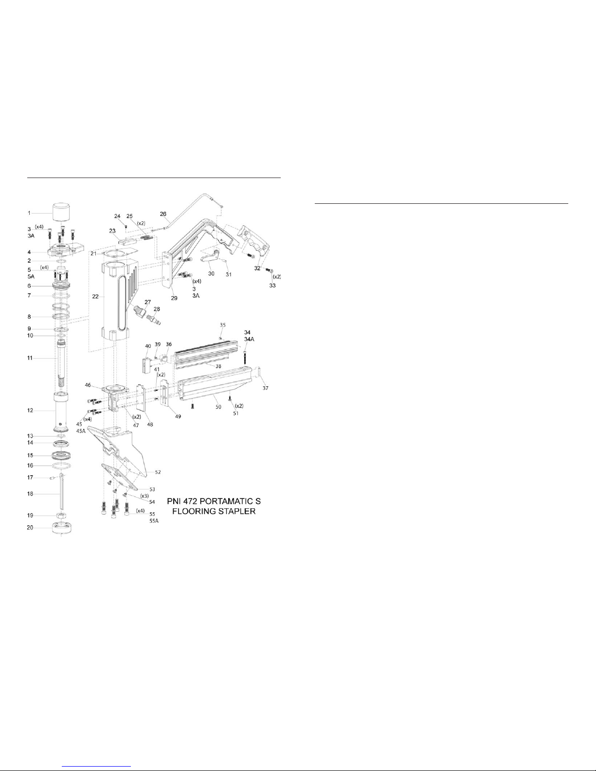
33 47074 SCREW – HANDLE CAP
34 47036 SCREW – MAGAZINE STAND-OFF
35 47048 ROLLER – SPRING
36 47044 CONSTANT FORCE SPRING
37 47037 MAGAZINE SPACER / STAND-OFF
38 47043 ROLLER WHEEL
39 47042 SCREW – CONSTANT FORCE SPRING
40 47041 PUSHER FINGER
41 47057 SPRING– COMPRESSION
42 47039 PUSHER BRACKET
43 47056 O-RING– PUSHER PIVOT PIN
44 47055 PUSHER PIVOT PIN
45, 45A 47028 SCREWS – FOOT / MAGAZINE
46 47029 FOOT
47 47032 SPRINGPIN – FOOT / DRIVER GUIDE PLATE
48 47031 DRIVER GUIDE PLATE
49 47033 NOSE – 470 – T/L
50 47034 MAGAZINE – 470 – T/L
51 47038 NUT – MAGAZINE / STANDOFF SCREWS
52 47027 SHOE
53 47025 SHOE BASE PAD
54 47024 SCREW – SHOE BASE
55, 55A 47026 SCREWS – SHOE / FOOT / BODY
56* 47047 LOCK NUT – SHOE BASE
57* 47075 HAMMER ASSY – GRAPHITE
*NOT SHOWN IN ILLUSTRATION