stpVx Phoenix User manual
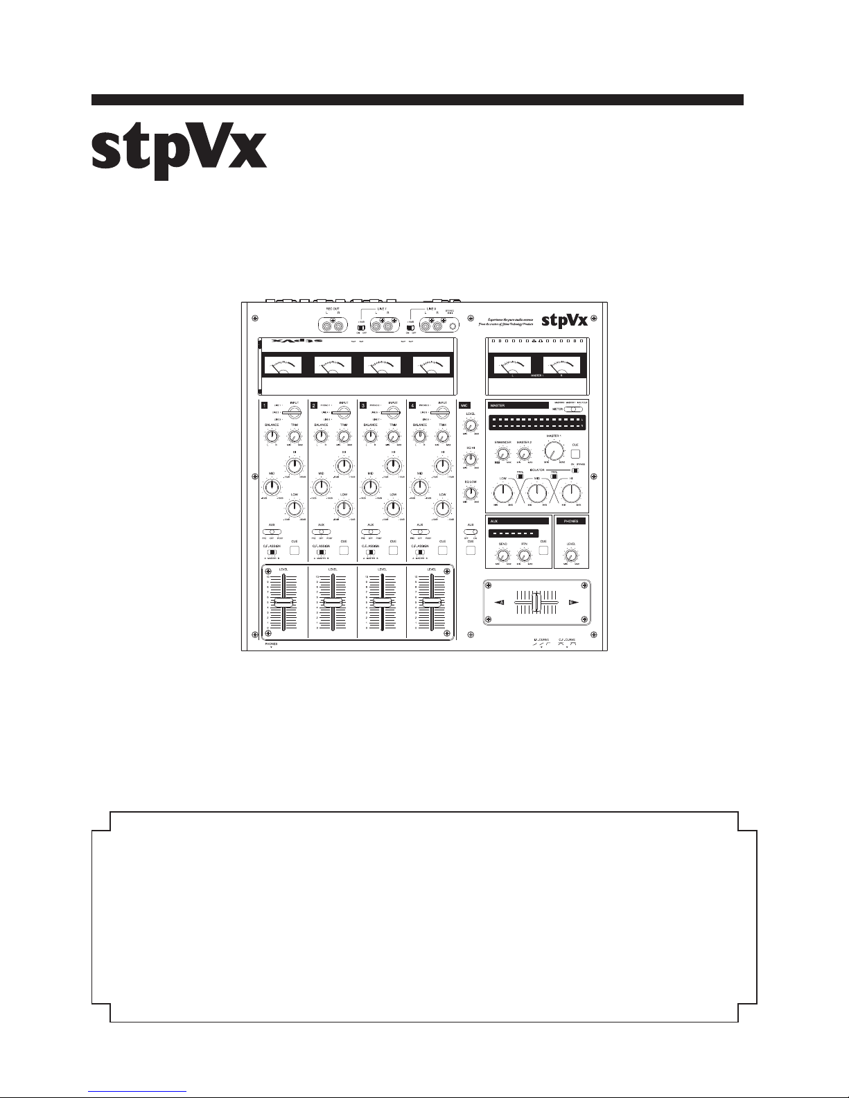
Thank you very much for purchasing STPVestax PHOENIX Professional DJ Mixer. Read this manual
thoroughly to get the most out of the performance of this DJ Mixer and also to use it safely. In
particular, please be sure to read “IMPORTANT SAFELY INSTRUCTIONS” prior to use.
PHOENIX -鳳凰-
ProfessionalDJMixer
USERMANUAL
-
25
-
10
-
5
-
1 0 +4 +6 dB
-
8
-
12
-
15
-
25
-
6
-
4
-
3
-
2
-
1 0 +1 +2 +3 +5 +8 dB
3
3
+
0
5
7
10
%
20
2
2
1
1
VU
3
3
+
0
5
7
10
%
20
2
2
1
1
VU
3
3
+
0
5
7
10
%
20
2
2
1
1
VU
3
3
+
0
5
7
10
%
20
2
2
1
1
VU
3
3
+
0
5
7
10
%
20
2
2
1
1
VU
3
3
+
0
5
7
10
%
20
2
2
1
1
VU
CONTENTS
2
5
5
6
5. SPECIFICATIONS
15
16
INTRODUCTION
IMPORTANT SAFETY INSTRUCTIONS
1.
MAIN FEATURES
2.
ACCESORIES
3.
NAMES AND FUNCTIONS
4.
WARRANTY AND AFTER-SALES SERVICE
6.
.....................................
..............................
..............................................................................
..............................................................................
.....................................................................................
..............................................................

-2-
※Inbelowdescription“thisdevice”includesdedicatedpowersupplyunit.
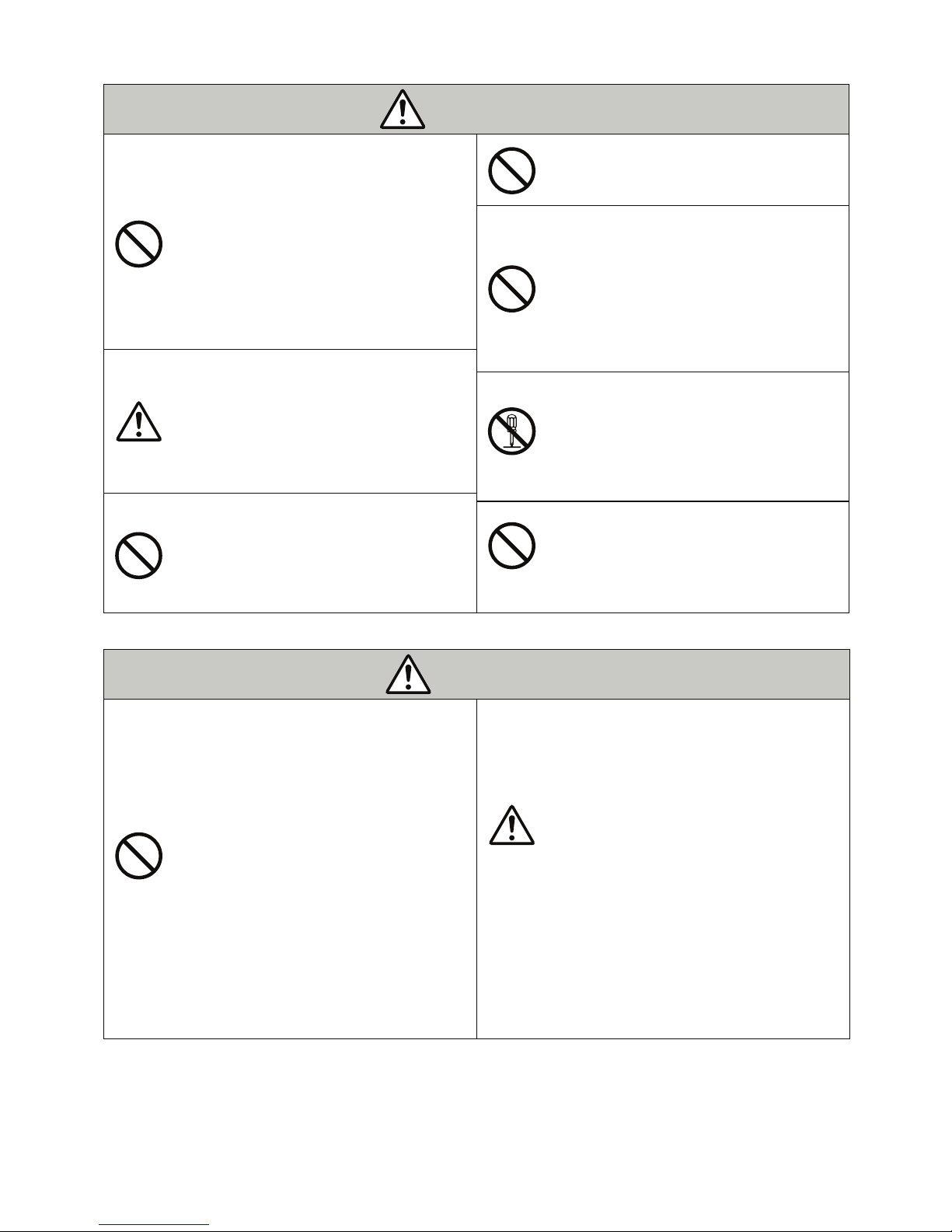
1. IMPORTANT SAFETY INSTRUCTIONS
EXPLANATION OF GRAPHICAL SYMBOLS
This Symbol indicates a prohibited action.
This Symbol indicates an action or instruction.
This Symbol indicates a warning or caution.
●
△
For correct operation and safety, please read this manual thoroughly prior to using your DJ mixer. After reading,
please ensure to keep this manual in a safe place for ready reference.
This “Safety Instructions” contain various pictorial symbols in order to use our product safely and correctly, to
prevent injury to you and other users, and to prevent damage to property. Please be sure to understand the
meaning of each symbol prior to reading on.
WARNING indicates a hazardous situation which, if not avoided and handling it
incorrectly could result in death or serious injury.
CAUTION indicates a hazardous situation which, if not avoided and handling it
incorrectly could result in minor or moderate injury, or only property damage.
Specific prohibited action (The left figure indicates do not disassemble) indicated by
transparent "No" circle-symbol.
Specific instruction (The left figure indicates the power plug is unplugged from the
power outlet) is illustrated.
Specific warning image (The left figure shows caution to not jam fingers) is illustrated.
WARNING
CAUTION
When the power cord is damaged (exposing
wire core, break in cable, etc.), ask your dealer
for a replacement. Continued use may cause
fire or electric shock.
●
●
●
Fire or electric shock may occur if you continue
to use this device when it is behaving abnor-
mally, such as smoke, unusual odor, or noise.
Turn off the power switch immediately and
unplug the power cord from the AC outlet.
Confirm that smoke does not come out and ask
your dealer for repair.
Fire or electric shock may occur if you continue
to use this device when water or liquid enter
the unit. Turn off the power switch immedi-
ately, unplug the power cord from the AC
outlet, and contact your dealer for advice.
Fire or electric shock may occur if you continue
to use this device when foreign objects are
placed in or enter the unit. Turn off the power
switch immediately, unplug the power cord
from the AC outlet, and contact your dealer for
advice.
Unplug the power
cord from the AC
outlet
Donotuse
nearwater
●Do not use in places such as bathrooms or
moist environments where the device is
exposed to water droplets or mist. It may cause
fire or electric shock.
Donottouch
●Do not touch the power cord during electric
storms. It may cause fire or electric shock.
● Do not use this device at a voltage other than
indicated voltage (AC 100V). It may cause fire
or electric shock.
● Do not allow water or fluids to enter or touch
this device. It may cause fire or electric shock.
Pay particular attention to usage of this device
in rain, snow, coastal or water-adjacent sites.
● Do not connect to a direct current (DC) power
source, such as used in a ship. It may cause a
fire.
WARNING
●Fire or electric shock may occur if you continue
to use this device when it is dropped or its
cabinet is damaged. Turn off the power switch
immediately and unplug the power cord from the
AC outlet, and contact your dealer.
Unplug the power
cord from the AC
outlet
●
●
●
●
●
●
Donot
diassemble
●
●
●
Do not insert or drop metals, flammable
materials etc inside the unit. This may result in
fire or electric shock. Be vigilant especially when
it is used by children.
Do not place small metal objects nor any
containers on top of this device, such as vases,
flower-pots, cups, cosmetics, chemicals or water
containers. Spillage or leakage may cause fire or
electric shock.
Do not remove the deviceʼs cover, cabinet or
rear panel. There are high voltage parts within,
and you may receive an electrical shock. Contact
your dealer for internal inspection, maintenance,
or repairs.
Do not modify this device. It may cause fire or
electric shock.
Do not place naked flame sources on top of the
device, such as lighted candles. It may cause
fire.
WARNING
Do not block the ventilation ducts. Blocked
ventilation ducts may cause heat to accumulate
inside and result in fire. This device has ventila-
tion ports both at the top and bottom of the
chassis to prevent internal temperature-rise.
Please pay particular attention to the following
recommendations:
・Do not place the device upside down, sideways
or face upwards.
・Do not push the device into any narrow and
poorly- ventilated space such as a bookcase or
closet.(other than on the dedicated rack).
・Do not cover the device with a table cloth or
place it on a carpet or bed.
When installing this equipment, keep 10 cm
space from the wall. Also, to improve heat
dissipation, keep it away from other equipment.
When mounting unit in a rack etc, ensure to
have a gap of more than 2 cm from the top
panel, more than 5 cm from the back. This will
prevent internal heat from rising - which if
trapped could cause overheating and fire.
Do not place heavy objects on the power cord
nor run the cord under heavy objects. The cord
may be damaged and this could cause fire or
electric shock. Be careful not to cover the cord
with rugs, matts etc, as you may inadvertently
place heavy objects on the cord without noticing.
Do not scratch, modify, bend, twist, pull, or heat
the power cord. A damaged cord is a fire and
electrical shock hazard.
●
●
●Do not place any location exposed to oil smoke
or steam, such as near cooking stoves,
humidifiers, etc. It may cause fire or electric
shock.
●Do not place the unit in a physically-unstable
situation such as an unsteady table or sloping
surface. Falling unit or collapsing operating-
bench may cause injury.
●Do not place the power cord close to a heater.
The coating of the cord may melt, causing fire or
electrical shock.
●Do not leave the unit in excessively hot environ-
ment, such as in a car with windows closed, or
exposed to direct sunlight etc. It may have a
negative influence on the cabinet and internal
parts, and could result in fire.
●Do not place unit in an excessively humid or
dusty environment. It may result in fire or
electric shock.
When connecting audio equipment, TV, video
equipment, game machine or speakers, make
sure to read the instruction manual of each
equipment carefully, turn off the power, and
connect accordingly as described.
Use only specified cable for connection. Using
non-specified cable or extending the cable may
cause overheating and cause burns.
Make sure to minimize the volume control before
turning on the power. A sudden loud blast of
sound may damage your hearing. Also, minimize
the volume control when you connect this
deviceʼs speakers with TV.
CAUTION
-3-

●
●
●
●
●
●
●
●
●
●
●
Even when the power switch is in the OFF
position, the unit is not completely isolated from
the power supply. In order to prevent accidents,
place this product near the AC outlet and so that
you can immediately unplug the power cord from
AC outlet in case of emergency.
●Do not place anything on top of this device.
There are vent holes on the top panel. Blocking
the ventilation holes may cause heat accumula-
tion inside and cause fire.
●Do not relocate unit while using with TV, audio
equipment etc. Falling or dropped device may
cause injury.
●Do not sit on nor hang from this device. Pay
attention especially when children are nearby.
Unit may fall or break, resulting in injury.
Do not use sound distortion through the unit for
long periods of time. This may cause your
speakers to generate heat and could result in
fire.
To move/relocate the device, turn off the power
switch, make sure to disconnect the power cord
from AC outlet, and remove all connected cables
between other devices. This is to prevent cord
damage and the potential to cause fire or electric
shock.
For safety, make sure to unplug the power cord
from the AC outlet whenever you do not use
the device for long periods of time, such as on
vacation etc.
When cleaning, unplug the power cord from AC
outlet for safety to prevent electric shock.
Do not plug or unplug the power cord with wet
hands. It may result in electric shock.
When disconnecting the power cord from AC
outlet, hold the power cord plug and never pull
the cord. A damaged power cord is a fire and
electrical shock hazard.
Do not handle the device during use nor immedi-
ately after use, except for the user controls and
rear connection terminals, as its high operating
temperature is a potential burn hazard. In
particular, do not touch the upper surface panel.
Do not place heavy or large objects on this
device that protrude from the outer frame. This
may upset balance and cause accidents resulting
in damage or injury.
Consult your dealer about internal servicing of
the unit once every five years. (In case of usage
public-space use in music bars etc, once a year
internal servicing is recommended). Dust may
accumulate inside the device when not cleaned
for a long periods of time. This may cause fire or
malfunction. In regions where high-humidity/
rainy-seasons are common, it is recommended
to clean units prior to that time. Consult your
dealer about service/maintenance fees.
Use only the specified AC cord which is included
in the product package. Do not use other
non-specified AC cords.
CAUTION
Unplug the power
cord from the AC
outlet
Unplug the power
cord from the AC
outlet
Unplug the power
cord from the AC
outlet
High temperature
-4-

-5-
●
●
●
●
●
●
●
●
●
●
•
•
2. MAIN FEATURES
3. ACCESORIES
The Phoenix Professional DJ Mixer is an all-round type 4CH mixer, created through careful design and
tapping the abundant development/experience history and knowledge-base of its sound equipment
master-craftspersons. It is manufactured using the highest technologies.
Full, rich analog sound is produced that could not be gained with a digital mixer through reviewing
the techniques of DJ mixer production history, as well as using original large toroidal transformers,
specially-selected parts, and adapting advanced discrete circuitry.
Encorporates professional VU meters for all channels, including a master channel, in order for ease
of accurate level-matching which is essential in the pursuit of high sound quality.
It consists of 4 channels to support 3 phono inputs and 9 line inputs. In addition, it is equipped
with an independent 1 MIC channel, separated AUX stereo send-return function and master loop
function. Besides the two outputs MASTER OUT1 and MASTER OUT2 which perform independent
volume control, there is also a separate REC OUT that does not pass through any volume-out
control.
Each of the 4 channels has a TRIM, LR balance control, and a high-quality 3-band equalizer that
has been fully tested for effectiveness. In addition, the ideal 60mm vertical fader is built in to offer
solid curve control.
The cross fader is an all genre type which can support long-mix play with longitudinal fades, to
scratch play performance with sharp cuts, by adapting the latest technologies for non-contact type
fader and curve control.
It is equipped with a Phono direct-out jack, and does not require replacing the record player cable
when connecting the interface - in order to support DVS with binary control.
Two LINE inputs for Φ 6.3 standard stereo phones. Other two LINE inputs are equipped with
switch for -10dB / 0dB to support the low volume level of the headphone jack output for portable
cellphone audio. It is also equipped with a Φ 3.5 mini stereo phone jack in one of the LINE inputs.
Equipped with a 3-band isolator in the master stage. Each of the Hi-Mid and Mid-Low dividing
points includes a critical two point switch, developed over many years of research.
With the integrated enhancer effector, it enables an unique sound outline finish correction, and
offers effects which can produced analog-circuits.
"Made in Japan" to the highest manufacturing, technology, and quality-control standards.
Included with the main unit are the following accessories:
Dedicated power supply
"Caution" notes for safety of use. (Please ensure to read it)

Main features and their functions can be divided into 3 panels:
Input channel panel
Master panel
Input/Output terminal panel
Input/Output
terminal panel
-6-
4. NAMES AND FUNCTIONS
-
25
-
10
-
5
-
1 0 +4 +6 dB
-
8
-
12
-
15
-
25
-
6
-
4
-
3
-
2
-
1 0 +1 +2 +3 +5 +8 dB
KYORITSU
KM-48
3
3
+
0
5
7
10
%
20
2
2
1
1
VU
KYORITSU
KM-48
3
3
+
0
5
7
10
%
20
2
2
1
1
VU
KYORITSU
KM-48
3
3
+
0
5
7
10
%
20
2
2
1
1
VU
KYORITSU
KM-48
3
3
+
0
5
7
10
%
20
2
2
1
1
VU
KYORITSU
KM-48
3
3
+
0
5
7
10
%
20
2
2
1
1
VU
KYORITSU
KM-48
3
3
+
0
5
7
10
%
20
2
2
1
1
VU
Input channel panel Master panel
Input/Output terminal panel
-7-
KYORITSU
KM-48
3
3
+
0
5
7
10
20
40
60
80
100
%
20
2
2
1
1
VU
KYORITSU
KM-48
3
3
+
0
5
7
10
20
40
60
80
100
%
20
2
2
1
1
VU
KYORITSU
KM-48
3
3
+
0
5
7
10
20
40
60
80
100
%
20
2
2
1
1
VU
KYORITSU
KM-48
3
3
+
0
5
7
10
20
40
60
80
100
%
20
2
2
1
1
VU
Input channel panel
①
② ③ ④ ⑤
⑬
⑭
⑮
⑯
⑰
⑥
⑦
⑧
⑨
⑩
⑪
⑫
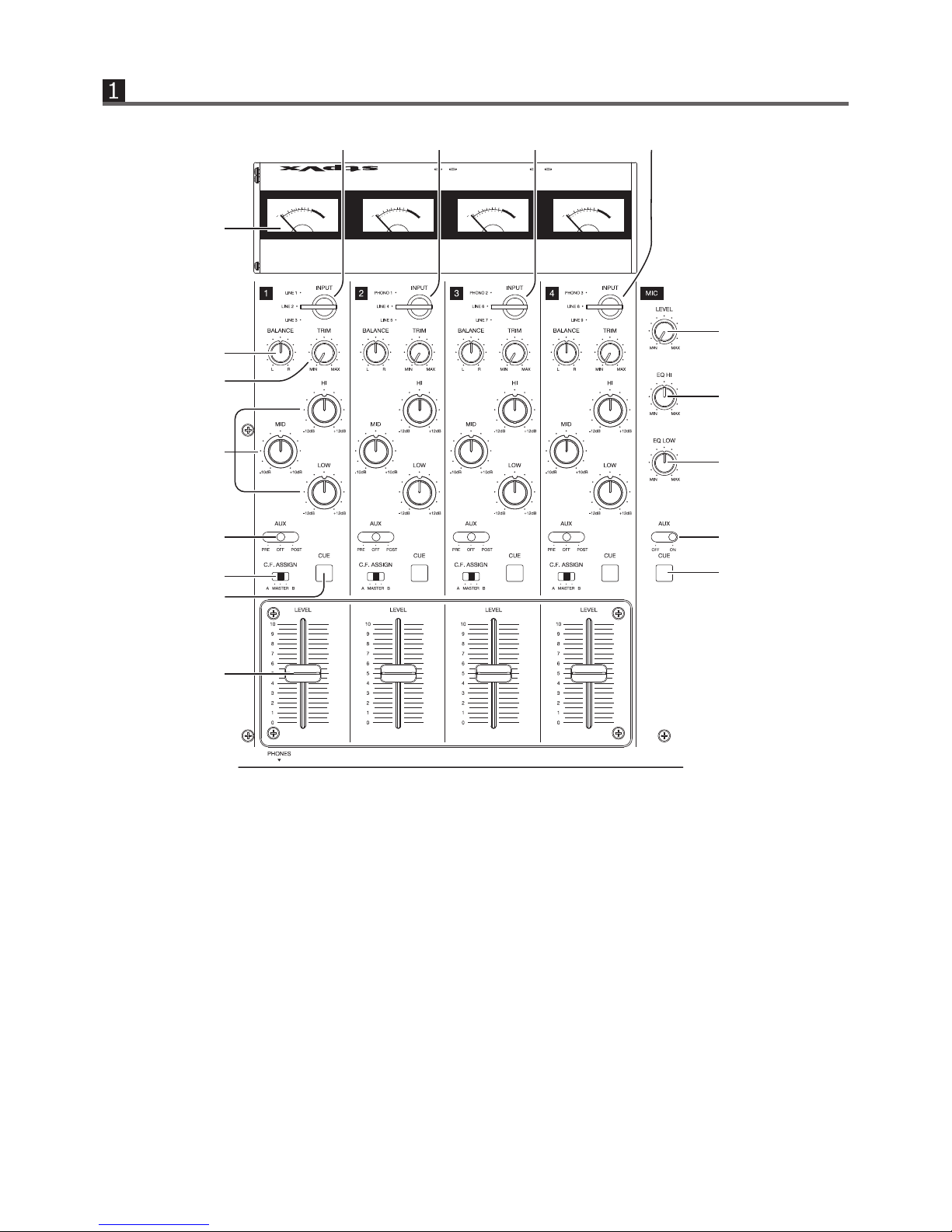
①INPUT VU METER
Displays the input level of each channel.
②INPUT SELECTOR 1
Selects the input to assign to CH1. Select one
input source from LINE1, LINE2 or LINE3.
③INPUT SELECTOR 2
Selects the input to assign to CH2. Select one
input source from PHONO1, LINE4 or LINE5.
④INPUT SELECTOR 3
Selects the input to assign to CH3. Select one
input source from PHONO2, LINE6 or LINE7.
⑤INPUT SELECTOR 4
Selects the input to assign to CH4. Select one
input source from PHONO3, LINE8 or LINE9.
⑦TRIM ADJUST VOLUME
Adjusts the input level by checking ①input VU
meter.
⑥LR BALANCE
Adjusts LR balance of each channel. The input
level difference of L and R can be checked
visually on LED level meter in master panel, by
switching the meter display menu to [INPUT
CUE] and pushing ⑪ CUE button of your
desired channel.

-8-
⑧CHANNEL 3BAND EQUALIZER
Adjusts Hi (high frequency range), Mid
(medium frequency range), and Low (low
frequency range) of each channel.Hi and Low
adjustable range are between -12dB to +12dB,
and Mid is between -10dB to +10dB.
⑨CHANNEL AUX SEND ON / OFF SWITCH
Determines whether to output that channel
from the AUX SEND jack. OFF is at center
position. When switched to the left (PRE), it
outputs with the max volume of the vertical
fader regardless of the position of the fader.
When switched to the right (POST), it outputs
with the volume determined by the vertical
fader.
⑩CROSS FADER ASIGN SWITCH
Determines whether the sound passed through
the vertical fader is assigned to the A or B side
of the cross fader, or is sent to MASTER with-
out assigning to the cross fader.
⑪CHANNEL CUE BUTTON
Press this button to select the channel for the
headphone monitor. LED lights while it is ON.
Press again to to turn it OFF (LED goes out). If
you turn on the CUE buttons on multiple
channels, they will be mixed, and can be
monitored together from the headphone.
⑫CHANNEL FADER (VERTICAL FADER)
Controls the volume of the channel. The curve
characteristics can be selected at Channel
fader curve control.
37
⑬MIC LEVEL
Controls the volume of the micprophone.
⑭MIC EQUALIZER Hi
Controls the high frequency ranges of the
microphone.
⑮MIC EQUALIZER Low
Controls the low frequency ranges of the
microphone.
⑯MIC AUX SEND ON/OFF SWITCH
Select whether or not to output the micro-
phone from AUX SEND jack.
⑰MIC CUE BUTTON
Select if outputting the microphone from AUX
SEND jack.

Master panel
-9-
-
25
-
10
-
5
-
1 0 +4 +6 dB
-
8
-
12
-
15
-
25
-
6
-
4
-
3
-
2
-
1 0 +1 +2 +3 +5 +8 dB
KYORITSU
KM-48
3
3
+
0
5
7
10
20
40
60
80
100
%
20
2
2
1
1
VU
KYORITSU
KM-48
3
3
+
0
5
7
10
20
40
60
80
100
%
20
2
2
1
1
VU
21
18
19
20
23
25
27
30
29
34
35
36
22
24
26
28
31
32
33
18
MASTER1 LEVEL VU METER
Indicates MASTER1ʼs output level. There are
2 master outputs; MASTER1/2 which can be
adjusted the volume individually.
19
LED LEVEL METER DISPLAY SWITCH
Selects the source to show on the LED level
meter. Left: MASTER2, Center: MASTER1,
Right; INPUT CUE. INPUT CUE shows the
level before passing through the vertical
fader, of which the CUE button of the four
channels can be pressed. This enables you to
check the volume and LR balance before
raising the vertical fader to output. You can
also visually check the level difference for
each channel by alternately pressing the CUE
button.
21
MASTER1 VOLUME
Determines the output volume of MASTER1.
Reference position is 14:00.
22
ENHANCER EFFECTS
Controls the volume of the effector that
outlines the sound. Apply it thinly for sound
field correction.
23
MASTER CUE
Turn ON to monitor MASTER output via
headphone. MASTER1/2 volume position is
ignored.
※ It starts in ON-state when the power is
turned ON.
24
MASTER2 VOLUME
Determines the output volume of MASTER2.
Reference position is 14:00.
25
ISOLATOR ON/OFF SWITCH
ISOLATOR ON/OFF SWITCH 3band isolator
ON/OFF witch. Right is OFF (by-passed) and
left is ON. OFF (by-passed) is recommended
if you do not use the isolator function.
26
Low-Mid DIVIDING POINT SWITCH
Switches 2 dividing points between Low and
Mid range of the isolator.
27
Mid-Hi DIVIDING POINT SWITCH
Switches 2 dividing points between Mid and
Hi range of the isolator.
20
LED LEVEL METER
Shows the level which is selected at .
19
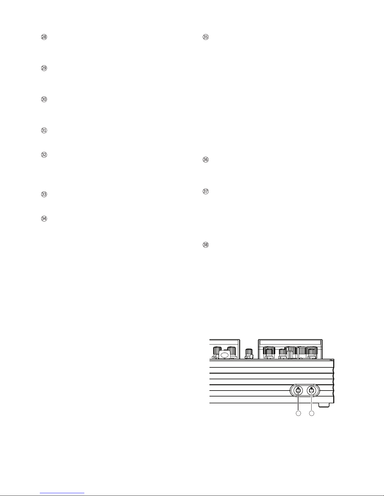
28
3BAND ISLATOR Low CONTROL
Controls the volume of low frequency range
between -∞ to +6dB. Flat at 12:00 position.
29
3BAND ISLATOR Mid CONTROL
Controls the volume of mid frequency range
between -∞ to +4dB. Flat at 12:00 position.
30
3BAND ISLATOR Hi CONTROL
Controls the volume of hi frequency range
between -∞ to +4dB. Flat at 12:00 position.
31
AUX RTN LEVEL METER
Indicates the input level of AUX return.
32
AUX SEND LEVEL
Controls the 4 input channels and MIC
channelʼs output level from the AUX send
jack, when the AUX lever is ON.
35
HEADPHONE VOLUME
Controls the output level of from the head-
phone jack (6.3mm stereo-phone) equipped
on the front left of the unit.
※ If the surroundings are too loud, the
headphone volume tends to be raised in
order to monitor steadily, but be sure to
guard against ear-damage when selecting
high volumes.
When tune-selecting or mixing, do not
depend on the monitor sound at 100% but
also refer to the VU meter or LED meter for
volume level and beat movement. (Combined
use of hearing and vision)
36
CROSS FADER
Crossfades the channel output which is
assigned to A or B on each channel.
37
CHANNEL FADER CRUVE CONTROL
Adjusts the curve characteristic of the rising
edge of the channel fader. Turning towards
the left gives more A-curve, the center is B
curve, and the right is a tight C curve setting
which sharply raises the sound.
38
CROSS FADER CURVE CONTROL
Adjusts the sharpness of the curve of the
crossfader. When it is Max, the curve rises
sharply. For example, the sound of A-side
assigned channel comes out just by sliding a
fader slightly from B-side edge and vise
versa. This setting is ideal for scratch play.
When it is at a minimum, it becomes a gentle
cross fade curve. At this setting, the sound
volume does not drop in both A side and B
side when the fader is on the center. This
setting is for a mixing-style using both a
crossfader and vertical fader together.
-10-
33
AUX RETURN LEVEL
Controls the input level of AUX return.
34
AUX CUE
Checks the AUX return input source via
headphone before raising its volume. LED
lights when it is ON, and press again to turn
it OFF.
37 38
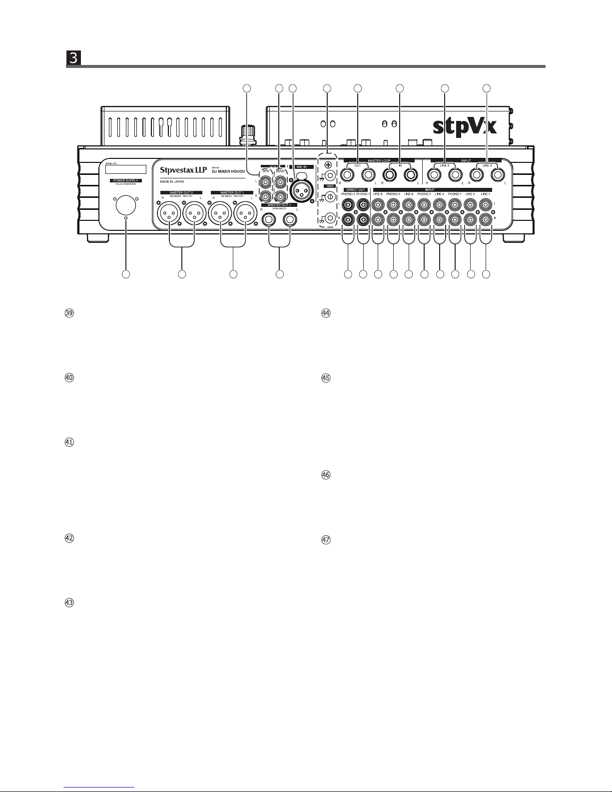
39
LINE1 INPUT TERMINAL (RCA Pin)
Input terminal for line level output devices
such as CD player or audio interface, and is
assigned to CH1.
40
LINE2 INPUT TERMINAL (RCA Pin)
Input terminal for line level output devices
such as CD player or audio interface, and is
assigned to CH1.
42
LINE4 INPUT TERMINAL (RCA Pin)
Input terminal for line level output devices
such as CD player or audio interface, and is
assigned to CH2.
41
PHONO1 INPUT TERMINAL (RCA Pin)
Input terminal for the record player (MM
cartridge supported), and is assigned to CH2.
(However, if the record player is phono
equalizer equipped and is set to line level
output, be sure to connect to the LINE input
terminal of this device.
43
PHONO2 INPUT TERMINAL (RCA Pin)
Input terminal for the record player (MM
cartridge supported), and is assigned to
CH3.(However, if the record player is phono
equalizer equipped and is set to line level
output, be sure to connect to the LINE input
terminal of this device.
44
LINE6 INPUT TERMINAL (RCA Pin)
Input terminal for line level output devices
such as CD player or audio interface, and is
assigned to CH3.
46
LINE8 INPUT TERMINAL (RCA Pin)
Input terminal for line level output devices
such as CD player or audio interface, and is
assigned to CH4.
47
LINE3 INPUT TERMINAL
(Φ6.3 standard mono phone)
Input terminal for line level output devices
such as CD player or audio interface, and
also for an audio mixer, keyboard or instru-
ment whose output source is line level. This
is assigned to CH1. (Only the terminal type is
different from other RCA pin LINE inputs.)
45
PHONO3 INPUT TERMINAL (RCA Pin)
Input terminal for the record player (MM
cartridge supported), and is assigned to CH2.
(However, if the record player is phono
equalizer equipped and is set to line level
output, be sure to connect to the LINE input
terminal of this device.
-11-
Input/Output terminal panel
56 55 54 53 52 51 48 47
60 59 58 57 50 49 46 45 44 43 42 41 40 39

-12-
48
LINE5 INPUT TERMINAL
(Φ6.3 standard mono phone)
Input terminal for line level output devices
such as CD player or audio interface, and
also for an audio mixer, keyboard or instru-
ment whose output source is line level. This
is assigned to CH2. (Only the terminal type is
different from other RCA pin LINE inputs.)
49
PHONO1 DIRECT OUTPUT TERMINAL
(RCA Pin)
Outputs PHONO1 input source directly. Use
this terminal for connecting an interface
(DVS) to use a control vinyl for digital DJ.
Recommended setting is; Keep the record
player connected to PHONO1 input, and
connect this PHONO1 direct output to the
PHONO input of the left-side DVS interface.
Then, connect the line output of the DVS
interface to LINE 4 or LINE 5 which are
assigned to CH2 as same as PHONO1. You
can now easily select input source either
from DVS or analog record, by just switching
the CH2's input selector switch.
50
PHONO2 DIRECT OUTPUT TERMINAL
(RCA Pin)
Outputs PHONO2 input source directly. Use
this terminal for connecting an interface
(DVS) to use a control vinyl for digital DJ.
Recommended setting is; Keep the record
player connected to PHONO2 input, and
connect this PHONO2 direct output to the
PHONO input of the right-side DVS interface.
Then, connect the line output of the DVS
interface to LINE 6 or LINE 7 which are
assigned to CH3 as same as PHONO2. You
can now easily select input source either
from DVS or analog record, by just switching
the CH3's input selector switch.
51
MASTER LOOP INPUT TERMINAL
(Φ6.3 standard mono phone)
This mixer can add external effectors
(isolator, equalizer, delay, reverb etc) just
before the final output stage. Connect the
output from to the external effector, and
return the output of effector to this terminal.
52
52
MASTER LOOP OUTPUT TERMINAL
(Φ6.3 standard mono phone)
This mixer can add external effectors
(isolator, equalizer, delay, reverb etc) just
before the final output stage. Connect the
output from this terminal to the external
effector, and return the output of effector to
this .
51
53
EARTH TERMINAL
Connect the earth of the record player. Up to
3 record players can be connected to this
mixer, thus 3 terminals are equipped. Be sure
to connect the earth otherwise noise will be
produced.
54
MIC INPUT TERMINAL (XLR Connector)
Connect the cable from microphone.
55
AUX OUTPUT SEND TERMINAL (RCA Pin)
Useful when applying external effectors
(delay, reverb, sampler, etc.) for a specific
channel. Connect to the input terminal of the
external effector.
56
AUX INPUT RETURN TERMINAL (RCA Pin)
Useful when applying external effectors
(delay, reverb, sampler, etc.) for a specific
channel. Connect to the output terminal of
the external effector.
57
21
Unbalanced output of final mix which level is
set at MASTER1 volume.
MASTER1 UNBALANCED OUTPUT TERMINAL
(Φ6.3 standard mono phone)
58
21
Unbalanced output of final mix which level is
set at MASTER1 volume.
MASTER1 BALANCED OUTPUT TERMINAL
(XLR Pin2-Hot)
Unbalanced output of final mix which level is
set at MASTER2 volume.
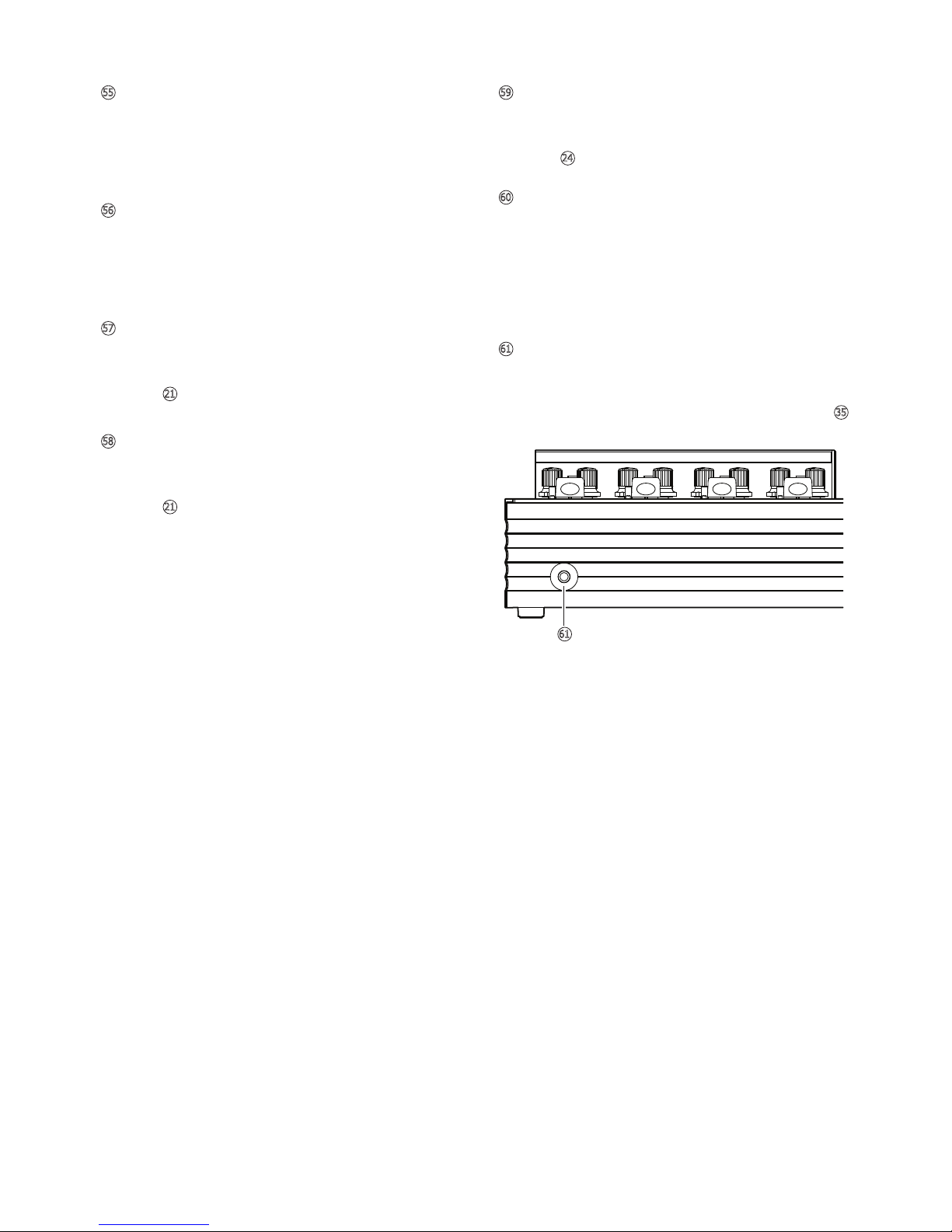
59
24
MASTER2 BALANCED OUTPUT TERMINAL
(XLR Pin2-Hot)
Connect the supplied power box.
※Do not use power supply other than the
one provided, even if the terminal/plug shape
is same. It may not only damage the unit but
also may result in a fire.
60
POWER SUPPLY TERMINAL
61
To hear the channel(s) for which CUE
button(s) is ON. Control the volume level at
61
35
HEADPHONE TERMINAL
(Φ6.3 standard stereo phone)
-13-
Outputs same sound as master. However, its
volume does not relate to the master volume,
and it outputs as the level of 14:00 position.
It is useful for recording the event mix.
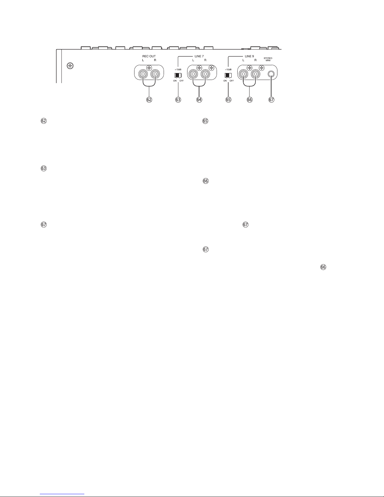
62
REC OUT TERMINAL
Switches the attenuator value of the sound
input to LINE7. Set it to OFF to connect a
normal LINE output device, and set +10dB
ON to input low level output device such as
mobile audio or smartphone.
63
LINE7 INPUT ATTENUATOR SWITCH
Terminal for LINE level output devices such
as CD player, audio interface, and for low
level output devices such as mobile audio or
smartphone. It is assigned to CH3.
67
LINE9 INPUT TERMINAL
Terminal for LINE level output devices such
as CD player, audio interface, and for low
level output devices such as mobile audio or
smartphone. It is assigned to CH4. However,
this input is disabled while the plug is
inserted to mini-stereo terminal.
66
67
LINE9 INPUT TERMINAL (RCA Pin)
-14-
Terminal for mini stereo input. If both RCA
pin terminal and this terminal are connected
at the same time, this mini stereo phone
takes precedence over RCA pin, and RCA
input is shut off. This is assigned to CH4.
67
66
LINE9 INPUT TERMINAL
(Φ3.5 mini stereo phone)
62 63 64 65 66 67
Switches the attenuator value of the sound
input to LINE9. Set it to OFF to connect a
normal LINE output device, and set +10dB
ON to input low level output device such as
mobile audio or smartphone.
65
LINE9 INPUT ATTENUATOR SWITCH

-15-
INPUT STAGE (Standard level / impedance)
CH1
-10dBv/10kΩ
LINE 3 IN φ6.3 Terminal×2 (Unbalanced) -10dBv/10kΩ
CH2
-52dBv(1kHz)/47kΩ
-10dBv/10kΩ
-10dBv/10kΩ
CH3
-52dBv(1kHz)/47kΩ
-10dBv/10kΩ
CH4
-52dBv(1kHz)/47kΩ
-10dBv/10kΩ
-10dBv/10kΩ
-10dBv/10kΩ
-50dBv/3.3kΩ
-10dBv/10kΩ
-10dBv/10kΩ
+4dBv/ ≧ 600Ω
0dBv/≧ 10kΩ
+4dBv/≧ 600Ω
-10dBv/≧ 10kΩ
-52dBv/≧ 10kΩ
0dBv/≧ 10kΩ
-10dBv/≧ 0kΩ
120mW(max)/ ≧ 8Ω
NOISE LEVEL (TRIM at 14:00 IFVR MAX MASTERVR at 14:00)
MASTER OUT
Power requirement
Power consumption
Dimensions
Weight
LINE IN →MASTER OUT 20
~20
kHz/+1.0dB-3dB
≦ 2mV
1kHz LINE IN →MASTER OUT≦ 0.5%
AC100V, 120V or 220V (depending on Region) 50/60Hz
95W
Unit:430mm(W) × 91mm(H) × 410mm(D)
(excl. meter housing)
430mm(W) × 120mm(H) × 410mm(D)
(incl. meter housing)
Power Supply:125mm(W) × 74mm(H) × 183mm(D)
Unit:11Kg
Power Supply:2.5kg (100V), 3.2kg (120V), 3.2kg (220V)
5. SPECIFICATIONS
LINE 1, 2 IN RCA Pin terminal (Unbalanced)
LINE 5 IN φ6.3 Terminal×2 (Unbalanced)
MASTER LOOP IN φ6.3 Terminal×2 (Unbalanced)
MASTER LOOP OUT φ6.3 Terminal×2 (Unbalanced)
HEADPHONE OUT φ6.3 Terminal (Unbalanced)
φ3.5 Stereo terminal (Unbalanced)
LINE 4 IN RCA Pin terminal (Unbalanced)
PHONO1 IN RCA Pin terminal (Unbalanced)
LINE 9 IN RCA Pin terminal (Unbalanced)
AUX RTN IN RCA Pin terminal (Unbalanced)
MIC IN XLR terminal (Balanced)
LINE 8 IN RCA Pin terminal (Unbalanced)
PHONO3 IN RCA Pin terminal (Unbalanced)
MASTER OUT1 XLR terminal (Balanced)
MASTER OUT2 XLR terminal (Balanced)
REC OUT2 RCA terminal (Unbalanced)
PHONO1,2 OUT RCA terminal (Unbalanced)
AUX SEND RCA terminal (Unbalanced)
MASTER OUT1 φ6.3 Terminal×2 (Unbalanced)
LINE 6,7 IN RCA Pin terminal (Unbalanced)
PHONO2 IN RCA Pin terminal (Unbalanced)
OUTPUT STAGE (Standard level / load impedance)
FREQUENCY CHARACTERISTIC (at rated input/rated output)
TOTAL HARMONIC DISTORTION (at rated input/rated output)
NB: For product improvements, specifications and appearance
are subject to change without notice.

6. WARRANTY AND AFTER-SALES SERVICE
(1)WARRANTY CARD
REPAIR QUESTION
REPAIR REQUESTS
NON-REPAIRABLE CASES AND CONDITIONS
REPLACEMENT UNIT DURING REPAIR PERIOD
※ The owner shall bear the freight-costs for repair, even within the warranty period.
(2) S
(3)
(4)
(5)
www.stpvestax.com
There is no printed warranty card included. The purchase date, owner information, and the serial
number of this unit will be registered and managed by “Stpvestax LLP”, and can be verified by the
dealer or owner by contacting the manufacturer “Stpvestax LLP” (stpvestax.com). (Privacy/Personal
data is strictly handled). If the unit's owner changes, the warranty period will be continued by verifica-
tion from both the previous owner and the new owner.
For unit failures or faults, immediately cease using it and request a repair from the original dealer from
whom you purchased the unit. (Even within the warranty period, repair fees may be charged depending
upon the nature and cause of the defect).
During the warranty period, repairs will be performed according to our warranty policy.
Following the expiration of the warranty period, the unit can be repair at your request. If you require an
estimate first, please tell us in advance. An "Estimate Fee" will also be charged, but it will be included in
that repair fee if you decide to proceed with the repair.
Repairs may not be possible, or we may refuse to repair a unit if it exhibits any of the following condi-
tions ... Faults caused by opening and modifying the unit by the Purchaser or 3rd Party. Additionally, in
the case where liquid-spillage from drinks or continued usage in wet environments has resulted in prior
repairs, the unit may fail again due to adjunct damage which develops over time. Therefore, a repair
cannot be guaranteed to prevent a recurrence of product failure or faults.
We are not able to offer a replacement unit during the repair period. If using our unit for business
purposes, we recommend you purchase a back-up machine as necessary.
If you have any questions or want to know more information, please visit our official website.
If for any reason, the original dealer from whom you purchased the unit has closed, please contact
“Stpvestax LLP” (stpvestax.com) for support.
For repair consultation and product questions, please contact your original dealer from whom you
purchased the unit, or “Stpvestax LLP” (stpvestax. Com)
Warranty period is one (1) year.
※ From the date from the original retail purchase.
Table of contents
Popular Dj Equipment manuals by other brands

Velleman
Velleman HQ Power Mini Mushroom 6 X 3 RGBWA user manual

Oase
Oase Jumping Jet Rainbow Flash II DMX/02 operating instructions

Lites
Lites PROFILE LED WHITE Owner's and service manual

Colorful Light
Colorful Light CL-BLC2B user manual

Pioneer
Pioneer EFX 500 - Dj Effector operating instructions

Chauvet DJ
Chauvet DJ Freedom Par T6 user manual


