Strand Lighting A21 74178 Original operating instructions

For use with the following a21™ 120V/277V Lighting Control Panels:
a21 3-Space Panel, a21 6-Space Panel, a21 9-Space Panel
TM
120V/277V Relay Module
Models: 74178 / 74179 / 74195 / 74196 / 74273 / 74293
Strand Lighting
www.strandlighting.com
© 2008 Strand Lighting
INSTALLATION & OPERATION GUIDE
3 YEAR LIMITED WARRANTY
Strand Lighting warrants that this product will be free from defects in workmanship or materials. This warranty is void on any electronic controls which have
been overloaded, abused, improperly installed or altered in any manner.
Strand Lighting's sole obligation will be at its option to repair or replace any electronic controls product proven defective if it is returned, postage prepaid, to
Strand Lighting, 6603 Darin Way, Cypress, CA 90630, USA. Strand Lighting will not pay for any charge-back or charge for labor or material that does not
have its prior written approval.
This warranty shall be in lieu of any other warranty, express or implied, including but not limited to any implied warranty of merchantability or fitness for a par-
ticular purpose. Some states do not allow limitations on how long an implied warranty lasts and do not allow the exclusion or limitation of incidental or conse-
quential damages, so the above limitation or exclusions may not apply to you. This warranty gives you specific legal rights, and you may also have other
rights, which vary from state to state.
Strand Lighting is a Philips group brand
Operating Voltage: 120VAC, 50/60Hz
Number of Circuits:
74178 / 74179: 2
74195 / 74196: 4
Min Rated Load (per circuit): 0.5W
Max Rated Load (per circuit):
74179 / 74195: 2400W
74178 / 74196: 1800W
Operating Voltage: 277VAC, 60Hz
Number of Circuits:
74273: 2
74293 : 4
Min. Rated Load (per circuit): 0.5W
Max Rated Load (per circuit):
74273 / 74293 : 4000W
Supported Load Types: Incandescent, Inductive, Magnetic Low
Voltage, Electronic Low Voltage, HID *
Cooling: Natural convection
Ambient Operating Temp: 0 to 40 degrees C
Relative Humidity: 5 to 95% (non-condensing)
* When controlling HID lamps, derating of the relay circuit by 20%
is required.
The a21™ Relay Modules offer economical and reliable switching of non-dim loads
including lighting, signs, and motors. The modules utilize rugged relays and feature dual-
color status indicators, and focus buttons for manual operation and testing.
All a21™ Modules have identical mounting dimensions, allowing them to be easily
swapped within any of the a21™ Lighting Control Panels. (Use caution to ensure that quad
modules are not installed into spaces wired for dual modules.)
Description
WARIG: Installing the module with power applied to the cabinet may
expose you to dangerous voltage and damage the device. Remove power before
installing. A qualified electrician should perform this installation.
Any combination of a21™ dimming and relay modules may be installed in the Lighting
Control Panel. Blank covers MUST be installed in any unused spaces. Pull the jumper
(shorting plugs) before installing.
To install relay modules:
1. Unpack module and recycle or properly discard packaging materials. (Be sure to
keep this instruction sheet for future use.) Inspect dimming module for signs of dam-
age during transit.
2. Disconnect main power to a21™ Lighting Control Panel.
3. Open module side of panel front cover.
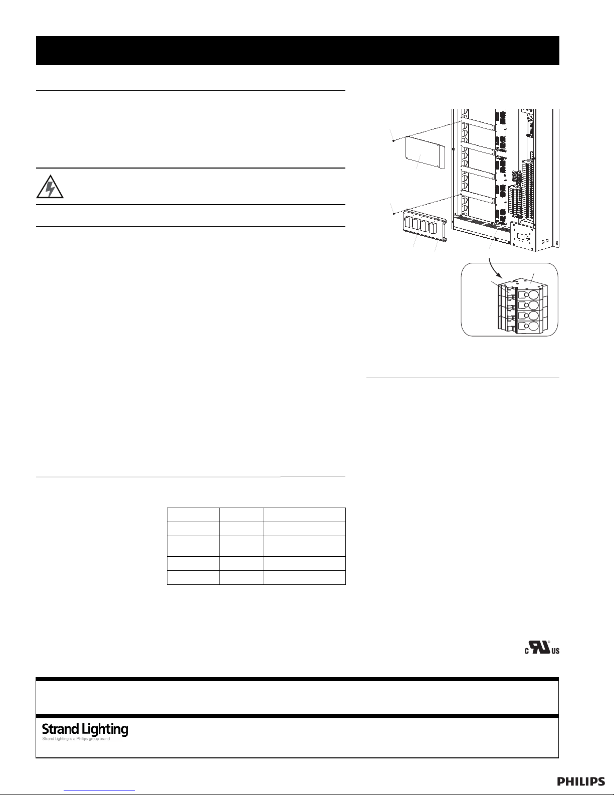
4. If present, remove blank cover from location where module is to be installed
(Figure 1). When possible, lower modules should be installed first.
5. Remove shorting plugs from the load terminal block. (The shorting plug is the red tab
protruding from the green load terminal block.) To remove, grasp the shorting plug
and gently pull. ote: The module will not operate properly if the shorting plug is
left in circuit.
6. Gently insert module into Lighting Control Panel with relays facing you. Secure
module using four screws (provided). ote: The connectors of 277VAC a21™ mod-
ules are keyed, preventing the insertion of modules into panels of the incorrect volt-
age. Do not force modules into slots.
7. Close panel front cover.
Blank Cover
(74181)
Screw (4)
Screw (4)
Load Terminal Block
Shorting
Plug
Terminal
DETAIL
Relay
Module
Focus Button
& Status LEDs
Figure 1: Installing Modules and Blank Covers
Installation Procedure
OTE: The a21™
9-Module Panel is used to
illustrate the installation in
Figure 1. However, the
module installation is
identical for all Lighting
Control Panel models.
Electrical Specifications
a21™ Relay Modules are
equipped with a "Focus Button"
on each circuit (Figure 1).
Tapping the focus button will turn
the circuit on, tapping it again
will turn the circuit off.
Operation
a21 LIGHTING CONTROL PANELS INSTALLATION & OPERATION GUIDEa21 RELAY MODULES INSTALLATION & OPERATION GUIDE
Status LED Indications:
Red LED Green LED Condition
Off Off Normal
Off On Focus Mode
(controlled at module)
On Off Communication Error
Flashing Flashing Miswire to Line
6603 Darin Way, Cypress, CA 90630, USA
Tel: +1 714 230 8200 | Fax: +1 714 230 8173
www.strandlighting.com ©2008 Strand Lighting
P/N: 85-5561A
Strand Lighting is a Philips group brand
This product may be covered by one or more of the following U.S. Patents: #4,413,211; 4,430,576; 4,465,956; 4,733,138; 4,792,731; 4,880,950; 4,988,840; 4,992,709; 5,004,969; 5,004,969;
5,128,654; 5,153,816; 5,189,259; 5,194,858; 5,239,255; 5,239,255; 5,371,439; 5,371,444; 5,506,480; 5,636,111; 5,642,104; 5,646,490; 5,814,550; 5,821,704; 5,920,156; 5,930,126; Des.
#307,578; 333,124; 435,203; 440,207; License #4482844; 5,004,969; 5,239,255; and corresponding foreign patents. Other Utility, Design and Foreign Patents Pending. We reserve the right
to change details of design, materials and finish in any way that will not alter the installed appearance or reduce function performance. Specifications are subject to change without notice.
This manual suits for next models
5


