Hopeland CL7206C4 User manual

User Manual of
CL7206C4 RFID Reader
Shenzhen Hopeland Technologies Co., Ltd

(V2.0.1)
Welcome to be user of Hopeland RFID products. Thanks for choosing Hopeland’s 4-port
Fixed RFID Reader CL7206C4. We believe our device will bring convenience for your work.

Catalogue
Catalogue.................................................................................................................................................................3
1. Technical Specification....................................................................................................................................... 6
1.1 Feature............................................................................................................................................................ 6
1.2 Technical.........................................................................................................................................................6
1.2.1 Main function..........................................................................................................................................6
1.2.2 Technical parameter..............................................................................................................................6
1.2.3 Operational environment.................................................................................................................... 7
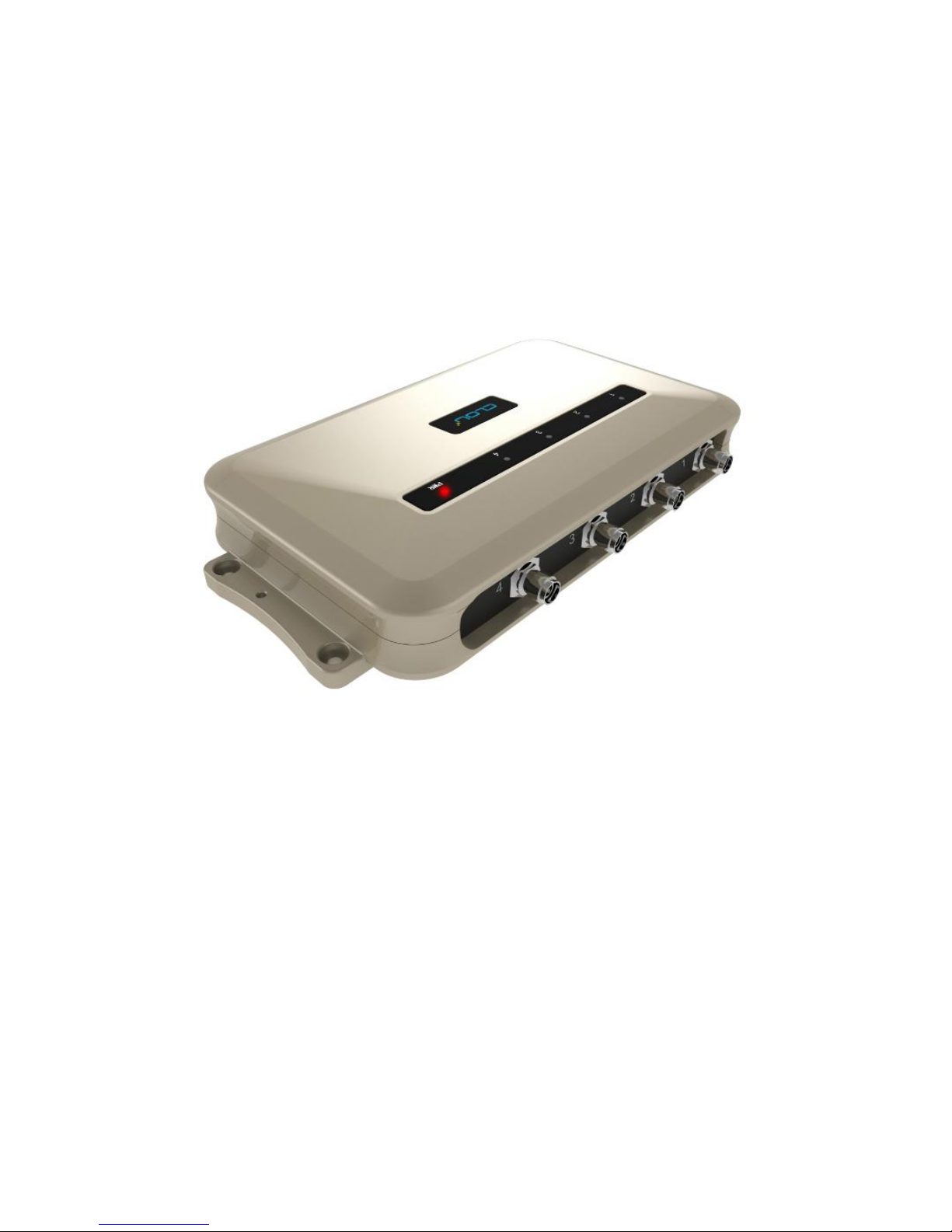
2. Sketch map..........................................................................................................................................................8
2.1 Physical construction................................................................................................................................... 8
2.2 Weight........................................................................................................................................................... 8
2.3 Illustration of LED display........................................................................................................................... 8
2.4 Interfaces.......................................................................................................................................................9
2.4.1 Power supply, communication and I/O interface............................................................................ 9
2.4.2 I/O Interface definition...................................................................................................................... 10
2.4.3 Coaxial RF Feeder Cable (optional).................................................................................................12
2.4.4 Network connection diagram.......................................................................................................... 12
3. Installation..........................................................................................................................................................14
3.1 Notes............................................................................................................................................................ 14
3.2 Installation conditions............................................................................................................................... 14
3.3 Device connection..................................................................................................................................... 14
3.3.1 Power on...............................................................................................................................................14
3.3.2 Antenna connection...........................................................................................................................15
3.3.3 PC connection.....................................................................................................................................15
3.4 Device installation...................................................................................................................................... 15

3.5 Acceptance................................................................................................................................................. 15
3.5.1 Acceptance of structure..................................................................................................................... 15
3.5.2 Performance acceptance.................................................................................................................. 16
4. Common failures..............................................................................................................................................17
4.1 Daily maintenance......................................................................................................................................17
4.2 Common failure analysis and solution................................................................................................... 17
5. Package.............................................................................................................................................................. 19
5.1 Package........................................................................................................................................................ 19
5.2 Accessories..................................................................................................................................................19
5.3 Storage environment................................................................................................................................ 20
6. After-sale service..............................................................................................................................................21

6
1. Technical Specification
1.1 Feature
CL7206C4 is a high performance four antenna port fixed UHF RFID reader; support
ISO18000-6C/6B protocols. The work frequency includes China standard dual frequency 920MHz ~
925MHz and 840MHz~845MHz, FCC 902MHz ~ 928MHz and ETSI 865MHz ~ 868MHz.
Output power from 0 ~ 33dBm optional, with long identification distance, fast reading speed,
high accurate rate, strong anti-interference ability, good protection performance and easy installation.
1.2 Technical
1.2.1 Main function
Air interface protocol: support ISO18000-6C/6B standard
Built-in LINUX operating system
Multiple communication port (Ethernet, RS232, RS485, USB), Wi-Fi, Bluetooth extensible
Support tag data filtering
Support RSSI: the intensity of the perceived signal
Adjustable RF output power
Optional working mode: constant frequency / frequency hopping
Support antenna detection function
Support online and remote upgrade
I/O interface: 4 port optocoupler input, 4 port relay output and Wiegand output
1.2.2 Technical parameter

7
Working frequency: GB 920MHz~925MHz, GB 840MHz~845MHz,
FCC 902MHz~928MHz, ETSI 865MHz~868MHz
Output power (port): 33dBm ± 1dB (MAX)
Power adjustment: 1 dB step-by-step
Reading distance: 0 ~8meters (depending on tags, antennas and environment)
Channel bandwidth: <200 KHz
RS232 serial communication rate: 115200bps (default), 19200 bps, 9600bps
RS485 interface communication rate: 115200bps (default), 19200 bps, 9600bps
Support: Wiegand 26, 34, 66 interfaces
Power supply: 10V ~ 30V(power capacity is not less than 60W)
Power adapter: AC input 100V ~ 240V, 50Hz ~ 60Hz
DC output: 24V/2.5A
High protection grade: IP54
1.2.3 Operational environment
Working environment: -20℃~+70℃
Relative Humidity: 5%RH~90%RH(+25℃)

8
2. Sketch map
2.1 Physical construction
Image 2-1 Structure diagram of CL7206C4
Size: 256mm*147.6mm*43.47mm
2.2 Weight
1.41kg
2.3 Illustration of LED display
Image2-2 Sketch map of reader’s LED indicator
LED indicator panel describe as below Form 2-1:
Form 2-1 LED indicator description
LED Mark NO.
Mark NO.
Status description

9
ANT1
Antenna 1 indicator
Indicates antenna 1 is working
ANT2
Antenna 2 indicator
Indicates antenna 2 is working
ANT3
Antenna 3 indicator
Indicates antenna 3 is working
ANT4
Antenna 4 indicator
Indicates antenna 4 is working
POWER
Power indicator
Keep bright indicates power supply working normally
2.4 Interfaces
2.4.1 Power supply, communication and I/O interface
Image 2-3 Sketch map of reader’s power supply, communication and I/O interface,
Details are shown in form 2-2
Form 2-2 Reader’s power supply, communication and I/O interface,
Interface ID
Interface Name
Detail description
POWER
Power supply
DC,10~30V, power capacity no less than 60W.
RJ45
Ethernet interface
10/100M Ethernet interface, the reader control and
communication interface.
USB DEVICE
USB device port
Connect PC or other upper computer, the reader control and
communication interface.

10
USB HOST
USB host port
For external U disk, wireless LAN card and other expansion
devices.
RS-232
RS-232 serial port
Serial port, the reader control and communication interface.
Other
I/O interface
See detailed definition 2.4.2.
2.4.2 I/O Interface definition
Image 2-4 Sketch map of I/O control interface
I/O control signal define as follow form 2-3
Form 2-3 I/O control signal definitions
Pin ID
Pin Description
R1
Relay 1# output; DC_MAX: 30V, 2A; AC_MAX: 125V, 0.3A; logic '0' indicates
open circuit, logic '1' indicates closed, default is open circuit.
L1
Relay 1# output; DC_MAX: 30V, 2A; AC_MAX: 125V, 0.3A; logic '0' indicates
open circuit, logic '1' indicates closed, default is open circuit.
R2
Relay 2# output; DC_MAX: 30V, 2A; AC_MAX: 125V, 0.3A; logic '0' indicates
open circuit, logic '1' indicates closed, default is open circuit.
L2
Relay 2# output; DC_MAX: 30V, 2A; AC_MAX: 125V, 0.3A; logic '0' indicates
open circuit, logic '1' indicates closed, default is open circuit.

11
R3
Relay 3# output; DC_MAX: 30V, 2A; AC_MAX: 125V, 0.3A; logic '0' indicates
open circuit, logic '1' indicates closed, default is open circuit.
L3
Relay 3# output; DC_MAX: 30V, 2A; AC_MAX: 125V, 0.3A; logic '0' indicates
open circuit, logic '1' indicates closed, default is open circuit.
R4
Relay 4# output; DC_MAX: 30V, 2A; AC_MAX: 125V, 0.3A; logic '0' indicates
open circuit, logic '1' indicates closed, default is open circuit.
L4
Relay 4# output; DC_MAX: 30V, 2A; AC_MAX: 125V, 0.3A; logic '0' indicates
open circuit, logic '1' indicates closed, default is open circuit.
GND
Ground
GND
Ground
IN1
Optocoupler 1# input, DC, 0~12V, higher than 9V is high level, lower than
8V is low level
IN2
Optocoupler 2# input, DC, 0~12V, higher than 9V is high level, lower than
8V is low level
IN3
Optocoupler 3# input, DC, 0~12V, higher than 9V is high level, lower than
8V is low level
IN4
Optocoupler 4# input, DC, 0~12V, higher than 9V is high level, lower than
8V is low level
IN_GND
Optocoupler input ground, reader optocoupler external input signal
ground
WG0
Wiegand data 0 signal, the default state is high level
WG1
Wiegand data 1 signal, the default state is high level
GND
Ground
485-A
RS485 A signal

12
485-B
RS485 B signal
2.4.3 Coaxial RF Feeder Cable (optional)
Image 2-6 schematic diagram of feeder line
RF cable TNC(Reverse polarity, internal thread, inner pin) connector connect with reader antenna
TNC connector, RF cable SMA connector connect with external circular polarization antenna’s SMA
connector, cable maximum length is 5m, impedance 50Ω, insertion loss is less than 2dB,
high-performance cable can also be selected, and the length can be increased appropriately,
insertion loss is less than 2dB.
Note: Poor contact of cable connector or an ultra-long RF cable can cause excessive attenuation
of the transmitted signal and received echo signal, resulting in deterioration of read/write
performance.
2.4.4 Network connection diagram
Network interface used for long-distance high-speed connection (less than 80 m), can be connected
with the switcher or router through the network cable, or directly connected with the PC network
interface, as shown in figure 2-7:

13
Image 2-7 Network application connection diagram

14
3. Installation
3.1 Notes
To ensure the normal and stable operation of the device and your personal property and safety,
please carefully read the following notes before install CL7206C reader and writer:
1. Firstly, check whether the power socket is connected to the ground, and to see whether the local
power supply voltage is in accordance with the applicable voltage range of the reader;
2. Check the device and the external connection if is closely connected;
3. Pay attention to the type selection and the length limit of the network cable and the serial cable:
Network cable connects directly, no longer than 80 meters
Serial cable connects directly, no longer than 10 meters
4. When installing several readers, the antenna position and the antenna spacing should be
appropriate to avoid interference with each other.
3.2 Installation conditions
Before installing the reader, please check carefully whether the product is in good condition and
the accessories are complete. If there is any parts missing or damage, please contact the supplier in
time.
3.3 Device connection
3.3.1 Power on
Insert the power cord into the AC power supply socket and plug another end into the power
connector of the device and tighten.
Turn on and wait about 20 seconds, the system initialization process is completed and is standby

15
state.
3.3.2 Antenna connection
The device built with four TNC coaxial cable connector for connecting an external antenna, select
low consumption RF cable, connectors should be tightened (Ensure to be waterproof when install
outdoors);
The reader antenna angle or tilt need to adjust to the best position through the actual test
according to the specific application.
3.3.3 PC connection
The device provides special adapter cable, including interface of network, serial and power,
RS232 interface is for short distance communication (less than 10m), through the DB9 connector
and the PC serial port connection to realize the communication of PC and the device,
RJ45 network port used for long distance communication (less than 80m), connect PC with
extend network cable.
3.4 Device installation
The reading and writing range of the reader depends on the on-site application, the tilt angle of
the antenna is adjusted to achieve the best reading and writing performance.
3.5 Acceptance
Mainly from two aspects of acceptance criteria: structure and performance.
3.5.1 Acceptance of structure
Check below details:
Whether reader is fixed firmly, without loose

16
Whether the cable connected firmly
Whether the screws are tighten
3.5.2 Performance acceptance
Whether the reader is working properly
Whether the read and write range is reasonable

17
4. Common failures
4.1 Daily maintenance
The routine maintenance of CL7206C4 usage:
☆To check whether the tightening of RF connector
☆To check if the screw fixed reader and antenna is loose
☆To check whether the RF cable connector is disconnected from the shielding layer
☆To check if the reader power cable connection is reliable
4.2 Common failure analysis and solution
Power supply system failures:
Check whether the power adapter is normal, and the AC supply voltage is between 100V ~ 240V.
The panel indicator light failed when power on:
Check whether the communication is normal; please contact customer service if it’s not normal.
The serial port unable to connect:
Check if the serial cable is not connected or connected unstable.
Check if the serial port connect baud rate of the reader is correct
Check if the selected COM port is right.
The network port cannot connect:
The default IP address and port of CL7206C is 192.168.1.116:9090, ensure the IP address of the PC
and reader in the same network segment, such as "192.168.1.XXX" then you can connect to the
reader, if you forget the IP address of the device, you can reset the reader’s IP address through the
serial port.
The reader can't read the tag

18
Check if the setting of antenna number is correct
Check if the label is damaged
Check if the label is placed in the reader's valid reading and writing range.
Check if the electromagnetic interference between the reader and the other device.
For the problem users cannot solve, please contact customer service.

19
5. Package
5.1 Package
Imag5-1 Carton box size
Carton box size: 313X296X82mm
5.2 Accessories
In order to facilitate the storage and transportation in near future, the packing box and the packing
material should be kept properly after unpack.
Besides of the device in the box, accessories equipped with the reader are also included in, please
check the product packing list to confirm whether the product and accessories are complete, if any
discrepancies or damage, please contact with the after-sale service in time.
The specific list of accessories as shown in table 5-1

20
Table 5-1 Package list
5.3 Storage environment
CL7206C fixed reader should be stored in below conditions:
☆ Environment temperature:-40℃~+85℃
☆ Relative humidity:5% RH~95%RH
NO.
Name
Material Code
Qty
Unit
Remark
1
CL7206C4 Four-port fixed reader
——————
1
set
Included
2
Power adapter 24V/2.5A
20109000000324
1
pcs
Included
3
AC power cord
20350000000195
1
unit
Included
4
Network cable
20350000000188
1
unit
Included
5
RS232 black cable
20351000000478
1
pcs
Included
6
USB cable
20351000000036
1
pcs
Included
7
9dBi circularly polarized antenna
20351000000035
4
pcs
Optional
8
Coaxial RF Feeder Cable
BRL-07 SMA-K--TNC-J reversed polarity
20351000000814
4
pcs
Optional
9
Mounting screws M4*28
W01-104028-100
4
pcs
Included
10
Warranty card
20420000001651
1
pcs
Included
11
Certificate of approval
20420000001650
1
pcs
Included
12
CD
N10-010000-002
1
pcs
Optional

21
6. After-sale service
Letter to Customers
Since our aim is to continuously improve our products for better user experience, we may modify
the product characteristics, composition and design of circuits without given notifications. Thus the
real product may be not in accordance with this manual. Generally, we will provide timely
amendments to this manual. If it’s not provided timely, please consult our service department.
Shenzhen Hopeland Technologies Co., Ltd.
Email: support@hopelandrfid.com
Tell: +86-755 36901035
Website: http://www.hopelandrfid.com
Address: Clou Buliding, Baoshen Road, Hi-tech Park North, Nanshan District, 518057, Shenzhen, China
Table of contents
Popular Other manuals by other brands

Westinghouse
Westinghouse De-ion DB-15 instructions

Bosch
Bosch TR2000 Series Installation and operating instructions

HTC
HTC VIVE Pro HMD user guide

American Eagle
American Eagle AEBTE quick start guide

Chubbsafes
Chubbsafes TRIDENT user manual

Buyers Products Company
Buyers Products Company LT30 installation instructions