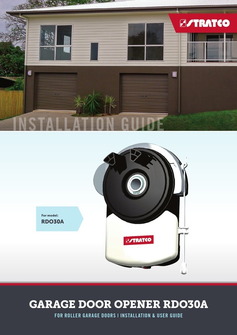
Stratco RDO12A User manual

FOR ROLLER GARAGE DOORS | INSTALLATION & USER GUIDE
GARAGE DOOR OPENER RDO12A
For model:
RDO12A
WARNING
Please read the manual carefully before installation and use. The installation of your new door
opener must be carried out by a technically qualified or licensed person. Attempting to install or
repair the door opener without suitable technical qualification may result in severe personal
injury, death and / or property damage.

2
CONTENTS
Important safety recommendations...……..……………………………
……………………..1
Preinstallation note
........................………………………………….………………………….2
Installation instructions
……………………………………………….………………………….3
Control box set up
…………………………………………….………………………………….4
Manual disengagement…………………………………………………………………………..7
Technical specifications……………………………………………………
………………..…...7
Common trouble shooting
……………………………………………………………………..….8
CONTENTS
3
4
5
6
9
9
10

3
1
IMPORTANT! PLEASE READ THESE INSTRUCTIONS CAREFULLY PRIOR TO
INSTALLATION OF THE ROLLER DOOR MOTOR.
This automatic opener has been designed to provide years of trouble free use. The opener will
perform efficiently only if it is installed and operated correctly.
READ THESE IMPORTANT SAFETY RULES FIRST.
Keep garage door balanced. Sticking or binding doors must be repaired. Garage doors, door
springs, brackets and their hardware are under extreme tension and can cause serious personal
injury. Do not attempt adjustment. Call professional garage door installers.
Do not wear rings, watches or loose clothing while installing or servicing a garage door operator.
Installation and wiring must be in compliance with your local building and electrical codes.
The safety reverse system test is very important. Your garage door must reverse on a contact
with a
5 to 10cm high object on the floor. Failure to properly adjust the operator may result in serious
personal injury from a closing garage door. Repeat the test once a month and make any needed
adjustments. (See Sensitivity adjustment).
ET-12A operator has an electronic obstruction system that provides safe and reliable operation.
It is however a legal requirement in some countries to also install a Photo-electric sensor across
the door way. Please check this requirement with your local distributor.
Do not use the force adjustments to compensate for binding or sticking garage doors. Excessive
force will interfere with the proper operation of the Safety Reverse System or damage the garage
door.
This unit should not be installed in a damp or wet space.
Disengage all existing garage door locks to avoid damage to garage door.
Install the lighted door Control Box (or any additional Push Buttons) in a location where the
garage door is visible, but out of the reach of children. Do not allow children to operate push
button(s) or remote control(s). Serious personal injury from a closing garage door may result
from misuse of the operator.
CAUTION: Activate operator only when the door is in full view, free of obstructions and operator
is properly adjusted. No one should enter or leave the garage while the door is in motion. Do not
allow children to play near the door.
Disconnect electric power to the garage door operator before making repairs or removing covers.
IMPORTANT: Label a caution mark to the rear of the garage door as a reminder of safe
operating procedures.

4
2
Pre-installation Notes
Right hand installation shown (inside garage looking out)Fig1
Check that there is sufficient side clearance to fit the operator unit. It may be fitted to either
the right or left hand side.
(1) Minimum side clearance:
The minimum side clearance between door
curtain and the inside edge of mounting
bracket is 85mm; The minimum side
clearance between door curtain and the
outside edge of mounting bracket is 135mm.
(2) Recommended side clearance The
recommended side clearance between door
curtain and the inside edge of mounting bracket
is 110mm;
The recommended side clearance
between door curtain and the outside
edge of mounting bracket is 160mm.
If the operator is being fitted at the same time as the new door installation, read these
instructions in conjunction with the roller door installation instructions.
If the operator is being retro-fitted, make sure the door operates smoothly and is properly
balanced.
N.B.: SPECIAL CARE SHOULD BE TAKEN IF RE-TENSIONING OF THE DOOR IS
REQUIRED.
At no stage should you loosen both “U” bolts if door is under tension.
IF THERE ARE ANY PROBLEMS PLEASE CONTACT YOUR LOCAL SUPPLIER OF
THIS OPERATOR.

5
3
Installation Instruction
STEP 1
Whilst the door roll is on the floor, rotate shaft
backwards and forwards by hand and then
release. This action will allow the roll to
centralize itself on the shaft.
(New installation only).
STEP 2
Fit anti-coning collar TIGHT TO DRUM at
opposite end of curtain to the motor using
M8 Dome Head Screw and M8 Nyloc Nut
as required. Figure 4.
STEP 3
Slide drive unit onto shaft as shown Figure 5.
Ensuring drive lugs engage fully with
the narrowest spoke on drum wheel.
N.B.: Right-hand installation shown (inside looking out)
Lift door onto mounting brackets (ensuring curtain roll is correct way round) centralize curtain
roll with
opening. Refer to door installation instructions. (New installations only).
Ensure motor assembly is fully engaged with drum wheel spokes. Clamp shaft to mounting
brackets using “U” Bolts supplied. (Use “U” bolt in opener pack for MOTOR end). See Figure 6.
Disengage the motor drive by pulling the manual release lever downwards. See Figure 6.
Tension door and complete door installation as per Door Installation Instructions. Ensure door is
correctly balanced and is not binding or sticking within vertical tracks.
Ensure locking bars (if fitted) are moved to the retracted (unlocked) position and keys removed
from the lock.
Mount control Unit approximately 1.6m from the floor out of the reach of children. Use No. 4x1”
self-tapping screws and raw l plugs. Ensure aerial is clear of all steel supports and coiled
electrical leads. Fit plug from motor unit into bottom of Control Box.
Connect the control unit power cord to an adjacent socket. Ensure that the socket is properly
earthed.

6
4
1. Control box set up
(
(
Remove cover on front of control box first.
)
)
Operation Controls:
1 SET Button - Confirm set and Reversing sensitivity
2 CODE Button - Transmitter code set.
3 UP Button - Limit mode set.
4 DOWN Button - Limit mode set
Circuit Board Connections.
5 Coupling for connecting the backup battery.
6 Coupling for connecting the motor and transformer.
7 Terminal connector to the control board.
8 Terminal connector to the control board.
9 Terminal connections for photo beam and push button.

7
5
2. Terminals and Connections.
1) GND & PB = Push Button terminals. Step by step command input (open, stop, close) same as
the step by step button on the transmitter.
2) 12V & GND & PE = Photo beam terminals.
3) 12V & GND & PB = Plug in receiver terminals
To safeguard the operator and avoid damaging components while wiring, disconnect the unit
from all power when working on it.
Remember that there are specific strict standards that must be complied with in regards to both the
safety of the electrical systems and the automatic doors.
Only qualified, trained personnel may carry out the installation and subsequent maintenance.
Whoever installs and uses the ET12A roller door opener will be held responsible for any
damage caused.
3. Right hand and left hand installation
Please note: The operator is designed to operate on the right side of the door by default.
To reverse the drive for left hand side installation, press and hold the SET button until the LED
displays 5.
Using the UP or DOWN buttons select 1 for left installation or 0 for right side installation.
Press SET to confirm the setting.
WARNING: This step must be completed prior to setting Open and Close limits and safety reverse
force adjustment if utilizing a lift side installation. If utilizing the standard right sided installation,
this step can be ignored.
4. Setting Open and Close Limits.
4.1) Press and hold SET button until the LED displays the letter1. It turns into opening learn state.
4.2) Now press and hold UP button, the door must travel to the open position, release the button
when the door has reached the desired open position.
4.3) If the door has overrun its open position, press the DOWN button to move the doordownwards.
Adjust and fine tune the open position by pressing UP and DOWN.
4.4) Press SET to store the open position, the LED will display the letter 2, it is now ready to set
the close position
4.5) Press and hold DOWN, the door must travel to the close position, release the button when
the door has reached the desired close position.
4.6) If the door has overrun its close position, press the UP button to move the door upwards.
Adjust and fine tune the close position by pressing DOWN and UP.
4.7) Press SET to store the close position.

8
6
The door will then open and close automatically to map the open and close sensitivity force
requirements.
4.8) The door is now set for normal operational mode.
IMPORTANT: Safety systems must be checked regularly to ensure that maximum safety is
maintained at all times.
5. Safety Reverse Force Adjustments.
The force settings must now be set. (Set force between 1 - 9)
5.1) Press and hold SET until the LED displays setting number 3, release SET, the force setting
number will appear from 1 – 9. It is now in force adjustment mode.
5.2) Press UP to increase the force by one degree and DOWN to decrease the force by one
degree. Maximum degree is 9 and the minimum degree is 1.
5.3) Press SET to store your setting.
5.4) If the door meets an obstruction it will stop and rebounds to the top.
6. Photo beam setting ( OPTIONAL).
Make sure the photo beam has been installed correctly before setting the Photo beam function.
6.1) Press and hold DOWN until the LED displays II.
6.2) Press UP once, the LED displays H, the photo beam is available, Press DOWN , the LED
displays II to cancel this function.
6.3)Press SET to store your setting.
Notice: Close the photo beam function when you don’t use photo beam.
7. Set Auto close setting.
7.1) Press and hold UP until the LED displays 0
7.2) Press UP once, the auto close time will increase by 1 minute, the maximum time is 9
minutes.
Press DOWN once, the auto close time will decrease by 1 minute. The LED will display the
current set value.
7.3) The Auto Close function will be disabled when the setting is 0.
7.4) Press SET to store your setting.
Notice: The auto close is only available when door is at its full open position. When using
auto close mode, a photo beam must be fitted correctly and tested for operation at
regular intervals.
8. Self Learning Transmitter. (Maximum 20)
8.1) Press CODE, the Red dot will light up.
Press and release a button on the transmitter, the Red dot will disappear, press the same
button again, the Red dot will flash and then be replaced by a U on the LED display.
Transmitter is programmed successfully.
8.2) Repeat step 1 to code a maximum of 20 transmitters onto the ET12 operator.
8.3) To master erase the ET12 receiver, press and hold CODE, the LED display dot will flash,
keep holding for approximately 8 seconds until the LED display flashes a C. Release
button. All transmitters are now deleted.

9
7
Manual disengagement
Pull manual release lever downwards. (Refer fig 10 below)
Figure 10
Technical Specifications
Model ET12A
Power Input: 220-240 VAC 50/60Hz
Motor: 18 VAC
Courtesy light time: 3 minutes
Relative humidity: <90 %
Reception frequency: 433.92 MHz
Transmitter power: 12V Battery
Working temperature: -20 C – 40 C
Open and close force: 600 N
Decoding: Rolling code
Lamp: LED, 12V DC
Operator limits travel: 6.5 circles of door drum wheel

10
8
COMMON TROUBLE SHOOTING
Symptom Possible reason Solution
The door will not operate from
control box
Power not switch on Check power is on to control unit(Red
LED illuminated)
Mains plug problem
Plug fully engaged on the control box
and motor wiring connections properly
engaged
“beep, beep.....” from buzzer, and
LED displays ”E2” error code
Motor fault
Push the manual release lever up
Change a new motor
Change a new rotary encoder
“beep, beep.....” from buzzer, and
LED displays ”E6” error code
Door twisted Fix the door
The door does not move, and
LED displays”8” error code Motor is too hot Wait for 15 minutes, then restart
The door does not move and LED
displays ”9” when self-learning
after set UP and DOWN limit
Door is too heavy Improve the weight balance of the door
The door won’t reverse when
obstructed
The moving force of the motor is
set too high Decrease the safety reverse force
The door reverses automatically
when closing
The moving force of the motor is
set too low Increase the safety reverse force

11
9
There could be an obstruction
under the door Remove obstruction
The door stops automatically
when opening
The moving force of the motor is
set too low Increase the safety reverse force
The operator can be controlled by
O/S/C button but not the remote
The remote light doesn’t flash The battery is loose. Open rear cover
and ensure battery is connected.
The receiving antenna is not
pulled out Pull out the receiving antenna
Low battery in remote Change new battery(12V)
The door can only open, cannot
close
The photocell function was
activated Close the photocell function
The motor rotates but the door
doesn’t move Motor put into manual mode Push the manual release lever up
The door closes when pressing
‘UP’ during limit setting Left / right installation error
Chang the installation direction
according to left/right installation setting
in the instruction manual

All brands and logos/images accompanied by ® or ™ are trade marks of Stratco (Australia) Pty Limited. ® Copyright March 2021
«SCAN THIS QR CODE TO FIND A STRATCO NEAR YOU
1300 155 155
stratco.com.au
Table of contents
Other Stratco Garage Door Opener manuals
Popular Garage Door Opener manuals by other brands

Novoferm
Novoferm Novomatic 563 S manual

Chamberlain
Chamberlain Merlin Professional MR850 Installation and operating instructions

Accessmatic
Accessmatic Raptor 120 user manual

Cardin Elettronica
Cardin Elettronica SL Series manual

Overhead door
Overhead door CD Series owner's manual

Simu
Simu GM600 installation instructions