2
SAFETY INSTRUCTIONS
These safety alert symbols mean WARNING : A possible risk to personal safety or property damage exists.
Keep the garage door balanced. Do not let the garage
door opener compensate for a binding or sticking garage
door. Sticking, binding or unbalanced doors must be
repaired before installing this opener.
Do not wear rings, watches or loose clothing while
installing or servicing a garage door opener. Wear gloves
and suitable protective clothing where appropriate.
Frequently examine the door installation. In particular
examine cable, springs and mountings for signs of wear,
damage or imbalance. Do not use if repair or adjustment is
needed since springs and hardware are under extreme
tension and a fault can cause serious personal injury.
To avoid serious injury from entanglement, remove all
ropes, chains and locks connected to the garage door
before installing the door opener.
Installation and wiring must be in compliance with your
local building and electrical codes.
The safety reverse system test is very important. Your
garage door MUST reverse on contact with a 40 mm
obstacle placed on the floor. Failure to properly adjust the
opener may result in serious injury from a closing garage
door. Repeat the test once a month and make any
necessary adjustments.
This appliance should not be used by children or persons
with reduced physical, sensory or mental capablities, or a
lack of experience & knowledge, unless they have been
given supervision or instruction concerning use of the
appliance by a person responsible for their safety.
Automatic Drive - Keep away from the area of the door
as it may operate unexpectedly.
WARNING! Product includes wireless transmitters and
wall controls that contain coin/button cell batteries. Keep
wireless devices and batteries away from children. Battery
can cause severe or fatal injuries in 2 hours or less if
swallowed or placed inside any part of the body. Seek
immediate medical attention if it is suspected that a coin/
button cell battery has been swallowed or placed inside
any part of the body.
The opener must not be used on a wicket door (door
within a door).
The Protector SystemTM (IR Beams) must be used for
all installations where the closing force as measured
on the bottom of the door is over 400 N (40 kgf).
Excessive force will interfere with the proper operation of
the safety reverse system or damage the garage door.
Installers must ensure that the doors are installed in a
compliant manner as per AS/NZS 60335-2-95.
After installation, ensure that the parts of the door do
not extend over public footpaths or roads.
Install the wireless wall control (or any additional wall
control) in a location where the garage door is visible
away from moving parts, at a height of at least 1.5 m
and out of the reach of children. Do not allow children
to operate push buttons or transmitters. Serious
personal injury from a closing garage door may result from
misuse of the opener.
Permanently fasten the warning labels in prominent
places, adjacent to wall controls and manual release
mechanisms as a reminder of safe operating procedures.
Activate opener only when the door is in full view,
free of obstructions and the opener is properly
adjusted. No one should enter or leave the garage
while the door is in motion.
Do not allow children to play near the door or with
door controls.
If the power cable is damaged, it must be replaced by the
manufacturer, its service agent or similarly qualified
persons in order to avoid hazard.
Disconnect electric power to the garage door opener
before making repairs or removing covers.
This opener should not be installed in a damp or wet
space exposed to weather.
KEEP THESE INSTRUCTIONS
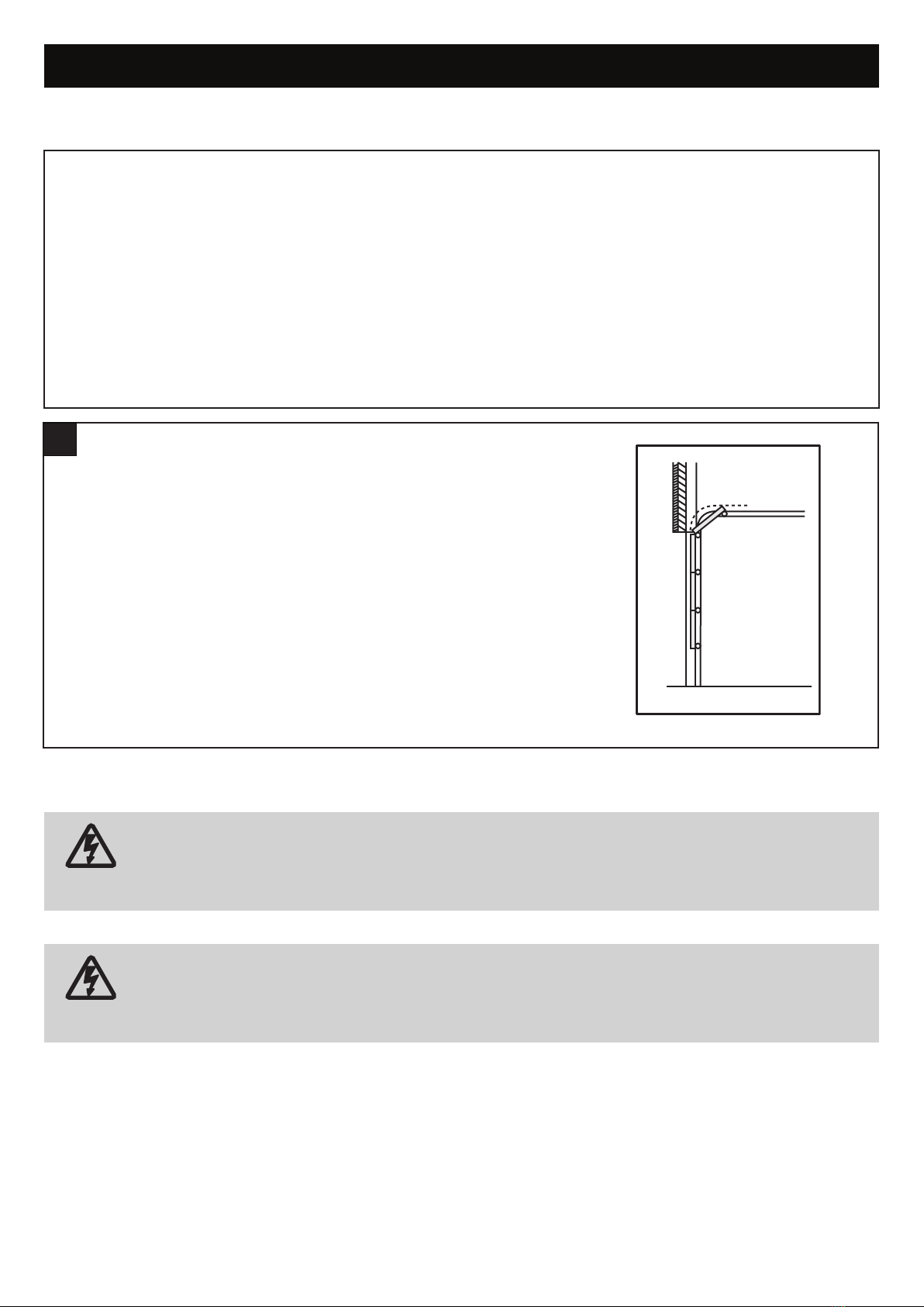
NOTE: If your garage has no service entrance door, we recommend an outside quick release must be installed. This
accessory allows manual operation of the garage door from outside in case of power failure.
CONTENTS PAGE
SAFETY INSTRUCTIONS 2
BEFORE YOU BEGIN 3
DOOR TYPES 3
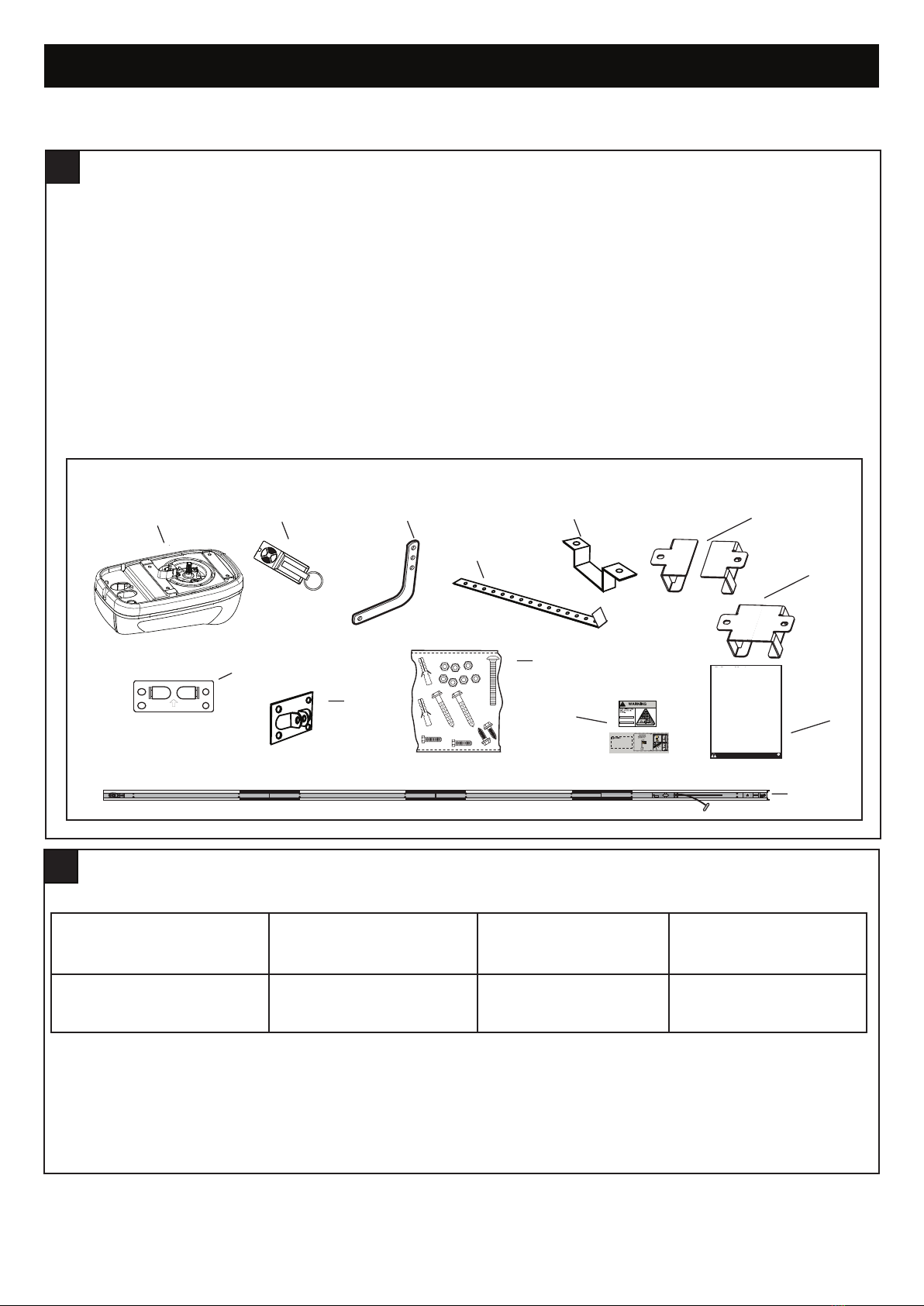
CARTON INVENTORY 4
RAIL SIZES 4
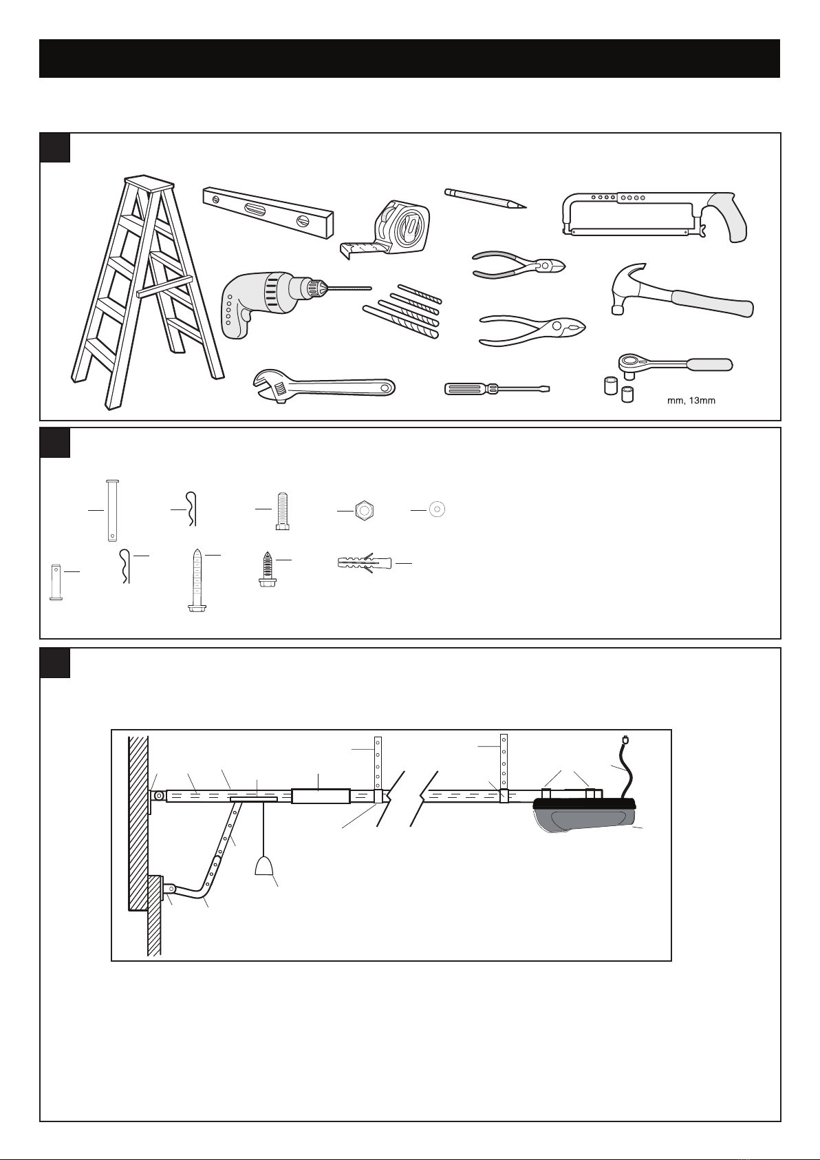
TOOLS REQUIRED 5
HARDWARE PROVIDED 5
COMPLETED INSTALLATION 5
CONTROL PANEL 6
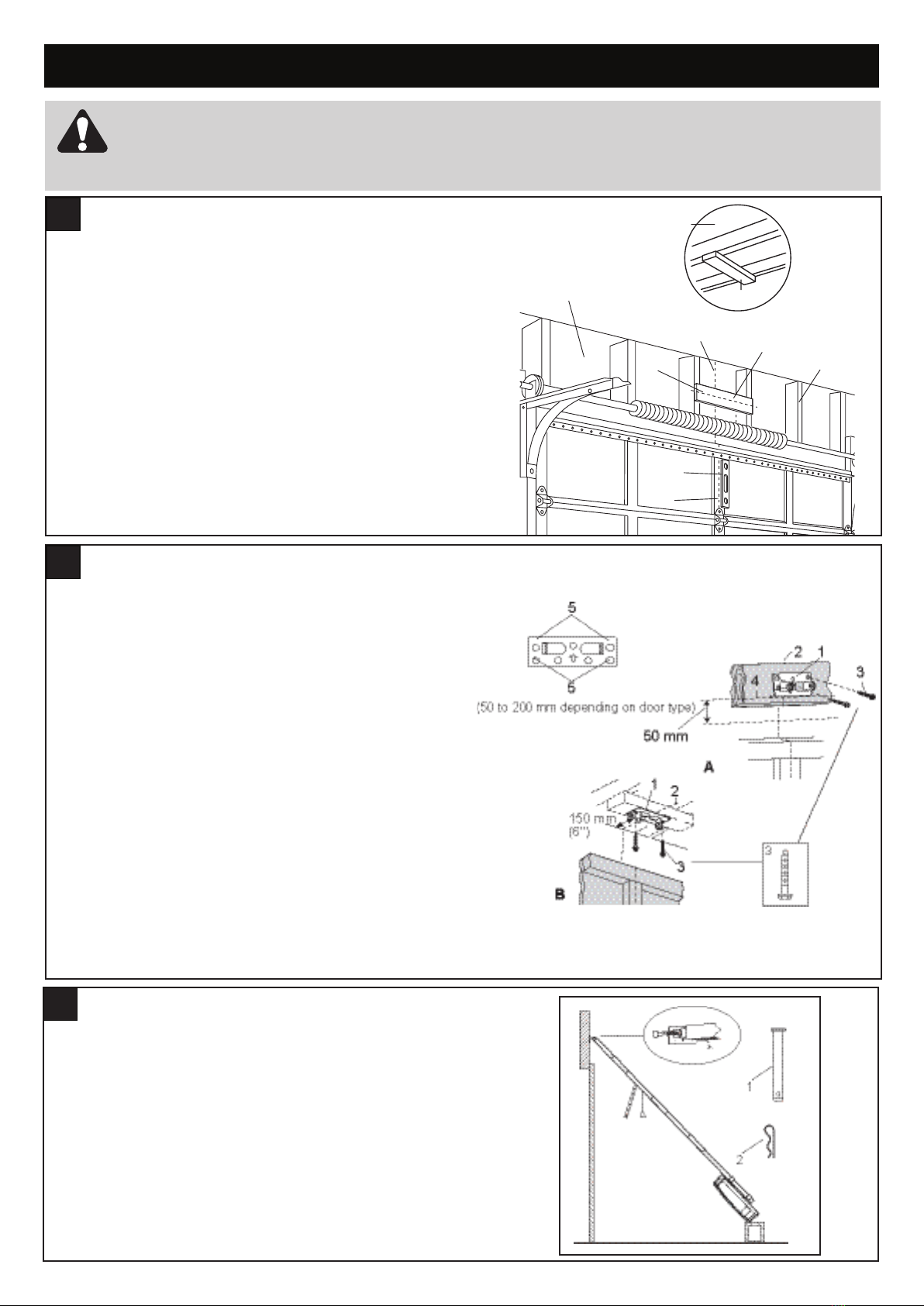
ASSEMBLY 7
INSTALLATION 8-11
PAGE
OPERATE MANUAL RELEASE 11
ADJUSTMENT 12-13
INSTALL THE PROTECTOR SYSTEM (OPTIONAL) 14
INSTALL WARNING LABELSS 15
WIRELESS PROGRAMMING 16
USING YOUR OPENER 17
CARE OF YOUR OPENER 17
REPLACE BATTERIES IN TRANSMITTER 17
SPECIFICATIONS 18
TROUBLESHOOTING 19
WARRANTY 20
WARNING
• Failure to comply with the following instructions may result in serious injury or property damage.
• Read and follow all instructions carefully.
• The garage door opener is designed and tested to offer safe service provided it is installed and operated in strict
accordance with the instructions in this manual.