1.0 INTEGRATION INTO AN EXISTING ROOF & WIND LOAD CAPABILITIES
The architect, builder or council is to ensure the existing
or new house/structure is of suitable structural integrity
and complies with all relevant Australian Building codes
and standards.
Roof structure suitability is based on the Solatop PV
panels, Panel Mount Brackets, Mounting Batten, Panel
Support Bracket and Gutter Tray’s having a combined
mass of 25kg per 1m2.
The roof rafters are to have a maximum spacing of
1200mm and to be in sound condition to withstand the
systems mass and environmental loading.
A water proofing membrane is required to be installed
between the Mounting Battens and Rafters. Sarking
membranes and sealing tapes, have to comply with local
requirements and building codes for fire resistance and
stability.
The Solatop PV panel system has been engineered for
residential applications in accordance with AS4055-2006
Wind loads for housing.
The system can withstand loads from wind class, up to
and including, N4 and a maximum wind speed of 50m/s
(permissible). Refer to your local authorities for wind
classification in the specific installation site area.
For more information regarding the suitability of the
house structure to accommodate the Solatop PV panel
system, consult a structural engineer or a building
authority.
It is the builder’s responsibility to ensure that the
existing house roof structure is capable of withstanding
additional loads imposed by the Solatop PV system.
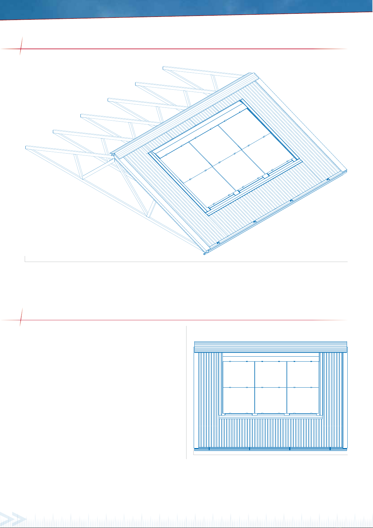
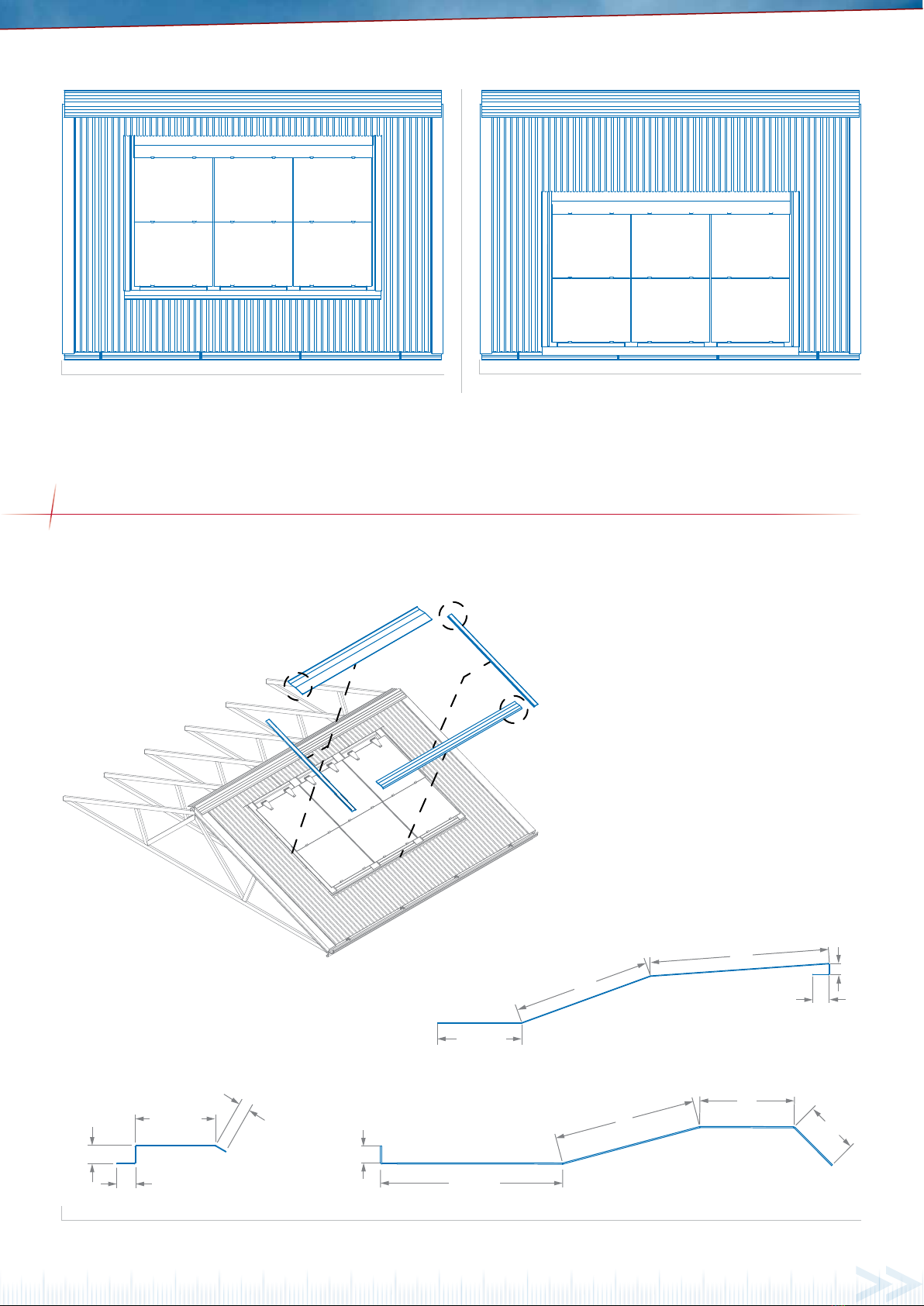
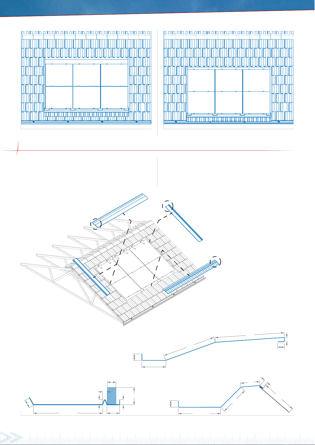
1.1 REQUIREMENTS FOR THE SUB-ROOF AND BATTEN CONSTRUCTION
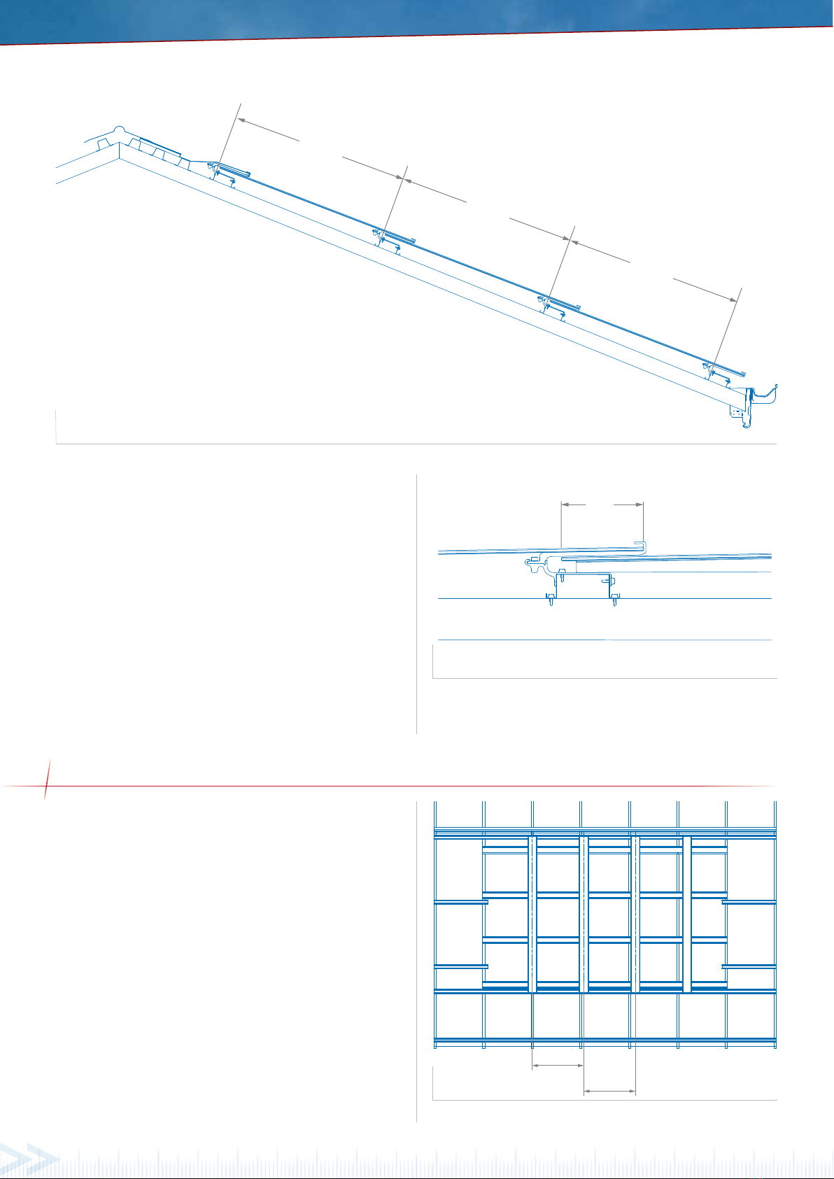
The Solatop PV panel system requires ventilation between
the overlapped panels, whilst being as water tight as
possible.
A sarking membrane is recommended to be installed on
top of the rafters, making sure the sarking membrane
is lapped from the top, downwards and sealed with the
tape at the lapping joint, to resist water penetration.
The sarking membrane is to be installed across the roof
rafters, loose enough to allow air flow underneath the
Solatop PV panels, but without the possibility of pooling
water.
The sarking membrane will need to exit and attach into
the gutter, without any pooling area’s in front of the
fascia.
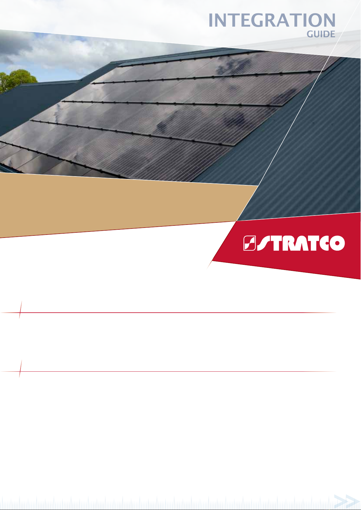
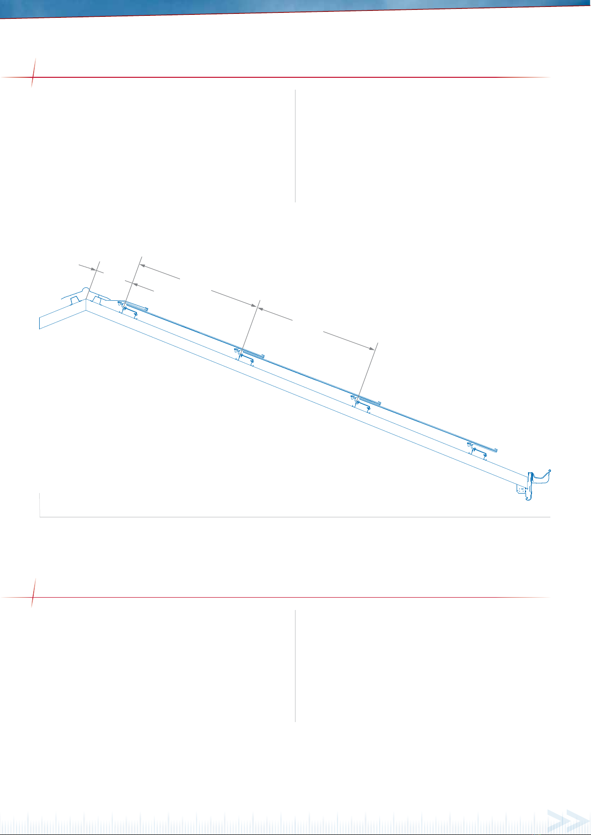
The Mounting Batten has been specifically designed
for the Solatop PV panel system. The Mounting Batten
spacing and placement is extremely important to the
finished array - battens must be planar and carefully
levelled if needed.
INTRODUCTION
This guide is intended for architects, builders and
experienced solar installers or individuals who have been
suitably trained and qualified.
Please read this layout guide thoroughly before
commencing the roof lay-out design. Double check
all dimensions, levels and locations when integrating
Solatop PV panels into the roof design.
It is recommended that the persons erecting the structure
have had some previous building experience because
some modifications to the existing house structure may
be required.
Stratco disclaims all liability for damages caused by
inadequate planning or faulty installation.