EG4 6000XP User manual
©2024 EG4 ELECTRONICS, LLC. ALL RIGHTS RESERVED.
VERSION 1.2 | INFORMATION SUBJECT TO CHANGE WITHOUT NOTICE.
MODEL #: EG4-6000XP
USER MANUAL
OFF-GRID INVERTER
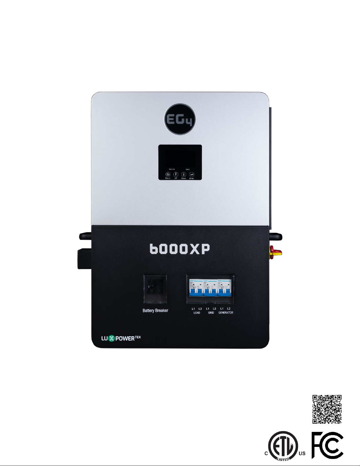
6000XP
SCAN FOR LATEST
DOCUMENTS


TABLE OF CONTENTS
1. TECHNICAL SPECIFICATIONS ............................................................................................................................ 1
2. ABBREVIATIONS.................................................................................................................................................. 3
3. SAFETY.................................................................................................................................................................. 4
3.1 SAFETY INSTRUCTIONS........................................................................................................................... 4
3.2 IMPORTANT SAFETY NOTIFICATIONS.................................................................................................. 4
4. BRIEF INTRODUCTION ....................................................................................................................................... 6
4.1 INVERTER FEATURES............................................................................................................................... 6
4.2 INVERTER INTERFACE ..............................................................................................................................7
5. INSTALLATION..................................................................................................................................................... 8
5.1 PACKING LIST............................................................................................................................................. 8
5.2 LOCATION SELECTION AND INSTALLATION ....................................................................................... 8
5.3 STORAGE INFORMATION ........................................................................................................................ 9
5.3.1 INSTALLING THE INVERTER ..............................................................................................................10
5.3.2 MOUNTING STEPS...............................................................................................................................10
5.4 CONNECTION OVERVIEW....................................................................................................................... 11
5.4.1 SYSTEM CONNECTIONS ..................................................................................................................... 11
5.5 PV CONNECTION ...................................................................................................................................... 11
5.5.1 CONNECTING PV TO THE INVERTER................................................................................................ 11
5.5.2 STRING SIZING......................................................................................................................................12
5.5.3 PV WIRING INSTRUCTIONS................................................................................................................13
5.6 BATTERY CONNECTION......................................................................................................................... 14
5.6.1 BATTERY CABLE CONNECTION........................................................................................................ 14
5.6.2 LITHIUM BATTERY COMMUNICATIONS..........................................................................................15
5.7 AC WIRING INFORMATION.....................................................................................................................16
5.7.1 STEPS FOR AC CONNECTION.............................................................................................................16
5.8 WORKING WITH A GENERATOR............................................................................................................17
5.8.1 GENERATOR SYSTEM CONNECTION ...............................................................................................17
5.8.2 INTEGRATED TWO-WIRE START/STOP .........................................................................................17
5.8.3 GENERATOR AC CONNECTIONS........................................................................................................18
5.9 GENERATOR START AND STOP SETTINGS.........................................................................................18
5.10 OFF-GRID...................................................................................................................................................19
5.10.1 OFF-GRID WIRING ...........................................................................................................................19
5.11 PARALLELING INFORMATION ...............................................................................................................19
5.11.1 PARALLEL COMMUNICATION CONNECTIONS ...............................................................................19
5.11.2 PARALLEL CONFIGURATION.............................................................................................................20
6. END USER SETTINGS.........................................................................................................................................21
6.1 APPLICATION SETTING...........................................................................................................................21
6.2 CHARGE SETTING.....................................................................................................................................21
6.2.1 GENERATOR CHARGE ........................................................................................................................ 22
6.3 DISCHARGE SETTING.............................................................................................................................. 22
6.4 RESET ........................................................................................................................................................ 22
7. INSTALLER SETTINGS...................................................................................................................................... 23
7.1 COMMON SETTING................................................................................................................................. 23

7.2 APPLICATION SETTING..........................................................................................................................24
7.3 CHARGE SETTING.................................................................................................................................... 25
7.4 DISCHARGE SETTING.............................................................................................................................. 26
7.5 OTHER SETTING...................................................................................................................................... 27
7.6 RESET ........................................................................................................................................................ 27
8. MONITOR SYSTEM SETUP..............................................................................................................................28
8.1 WI-FI/4G/LAN DONGLE CONNECTION ..............................................................................................28
8.2 THIRD-PARTY RS485 COMMUNICATION ..........................................................................................28
8.3 ONLINE MONITORING SYSTEM USER INTERFACE........................................................................... 29
8.3.1 DASHBOARD (MONITOR TAB) ......................................................................................................... 29
8.3.2 DASHBOARD (DATA TAB) ................................................................................................................. 32
8.3.3 DASHBOARD (CONFIGURATION TAB) ............................................................................................ 35
8.3.4 DASHBOARD (OVERVIEW TAB) ....................................................................................................... 36
8.3.5 DASHBOARD (MAINTENANCE TAB) ............................................................................................... 37
9. FIRMWARE UPDATES ...................................................................................................................................... 37
9.1 FIRMWARE UPDATE VIA EG4 ELECTRONICS APP............................................................................ 37
9.2 FIRMWARE UPDATE VIA MONITOR CENTER (WEBSITE) ...............................................................38
10. SMARTPHONE APP SETUP .............................................................................................................................40
11. WORKING MODES............................................................................................................................................. 41
11.1 RAPID SHUTDOWN (RSD) .....................................................................................................................42
11.1.1 EXTERNAL RSD WIRING INSTRUCTIONS.......................................................................................43
11.2 LCD DISPLAY AND SETTINGS ...............................................................................................................44
11.2.1 LCD DISPLAY........................................................................................................................................44
12. LCD SETTINGS ...................................................................................................................................................46
13. INVERTER START-UP AND SHUT-DOWN PROCEDURE............................................................................ 56
13.1 START-UP................................................................................................................................................. 56
13.2 SHUT-DOWN............................................................................................................................................ 56
14. ERROR/WARNING TABLES............................................................................................................................. 57
14.1 ERROR DEFINITIONS AND TROUBLESHOOTING .............................................................................. 57
14.2 WARNING DEFINITIONS AND TROUBLESHOOTING......................................................................... 58
15. INVERTER MAINTENANCE.............................................................................................................................. 59

1
1. TECHNICAL SPECIFICATIONS
AC INPUT DATA
NOMINAL AC VOLTAGE
120-240VAC
FREQUENCY
50/60Hz
MAX. CONTINUOUS AC CURRENT
37.5A @ 240VAC
MAX. AC INPUT POWER
9000W
AC BYPASS (GRID | GENERATOR)
50A | 50A
AC OUTPUT DATA
OUTPUT VOLTAGE
120/240VAC
OUTPUT FREQUENCY
50/60Hz
MAX. CONTINUOUS OUTPUT CURRENT @ 240V
25A
MAX CONT. LINE WATTAGE
3000W
NOMINAL POWER OUTPUT
6000W
SURGE CAPACITY
12,000W for ≈3.5 seconds | 11,000W for ≈5 seconds
POWER FACTOR VALUE
0.6 – 1
OPERATING FREQUENCY
50/60Hz
THD (V)
<3%
SWITCHING TIME
<15ms @ Single / <30ms @ Parallel
PV INPUT DATA
NUMBER OF MPPTS
2
INPUTS PER MPPT
1
MAX. USABLE INPUT CURRENT
17/17A
MAX. SHORT CIRCUIT INPUT CURRENT
25/25A
DC INPUT VOLTAGE RANGE
100-480 VDC
UNIT STARTUP VOLTAGE
100 VDC ± 10 VDC
MPP OPERATING VOLTAGE RANGE
120-385 VDC
NOMINAL MPPT VOLTAGE
320 VDC
MAXIMUM UTILIZED SOLAR POWER
8000W (4000W per MPPT)
RECOMMENDED MAXIMUM SOLAR INPUT
10000W (5000W per MPPT)
EFFICIENCY
MPPT EFFICIENCY
99%
BATTERY CHARGING EFFICIENCY
93%
BATTERY DISCHARGING EFFICIENCY
93%
IDLE CONSUMPTION (STANDBY MODE*)
W/ PV
<30W
w/ Battery
≈50W
w/ AC
<50W
BATTERY DATA
TYPE
Lead-acid/Lithium
MAX. DISCHARGE CURRENT 140A
MAX. CHARGE CURRENT 125A**
NOMINAL VOLTAGE 48 VDC
BATTERY VOLTAGE RANGE 46.4-60 VDC (Lithium); 38.4-60 VDC (Lead-Acid)
REC. BATTERY CAPACITY PER INVERTER >200Ah
HIGH DC CUT-OFF VOLTAGE 59 VDC (Lithium) | 60 VDC (Lead-acid)

2
STANDARDS AND CERTIFICATIONS
UL1741
FCC PART 15, CLASS B
INGRESS PROTECTION RATING
IP20
*Idle consumption value tested with constant 300VDC PV source
**115A @ 48VDC (AC), 125A @48VDC (PV)
***See EG4 Warranty Registration for terms and conditions
HIGH DC RECOVERY VOLTAGE 57.4VDC(Lithium) | 58VDC(Lead-Acid)
LOW DC WARNING VOLTAGE (LEAD-ACID)
LOAD<20% 44.0 VDC (Configurable)
20%≤LOAD<50% Warning Voltage @Load <20% - 1.2V
LOAD≥50% Warning Voltage @Load <20% - 3.6V
LOW DC WARNING VOLTAGE RETURN (LEAD-ACID) Low DC Warning Voltage @Dierent Load +2V
LOW DC CUT-OFF VOLTAGE (LEAD-ACID)
LOAD<20% 42.0VDC (Configurable)
20%≤LOAD<50% Cut-O Voltage @Load <20% - 1.2V
LOAD≥50% Cut-O Voltage @load <20% - 3.6V
LOW DC CUT-OFF RETURN VOLTAGE (LEAD-ACID)
CUT-OFF VOLTAGE
@LOAD <20% ≥45V
CUT-OFF VOLTAGE
@LOAD <20% <45V
Low DC Cut-O Voltage @load <20% +3V
48V
LOW DC WARNING SOC
20% SOC (Configurable)
LOW DC WARNING RETURN SOC Low DC Warning SOC +10%
LOW DC CUT-OFF SOC
15% SOC (Grid ON) (Configurable)
15% SOC (Grid OFF) (Configurable)
LOW DC CUT-OFF RETURN SOC Low DC Cut-O SOC +10%
CHARGE CUT-O F F V O LTA G E 58.4VDC
GENERAL DATA
MAX. UNITS IN PARALLEL
16
INTEGRATED DISCONNECT
Yes
DC SWITCH RATING FOR EACH MPPT
Yes
DIMENSIONS
18×25.5×5.25 in (457×648×132mm)
WEIGHT
52.9 lbs. (24kg)
COOLING CONCEPT
Fan
TOPOLOGY
TL (Transformerless)
RELATIVE HUMIDITY
5-95%
ALTITUDE
<6561ft (2000m)
OPERATING TEMPERATURE RANGE
32 – 113°F (0 – 45°C)
STORAGE TEMPERATURE RANGE
5 – 140°F (-15 – 60°C)
NOISE EMISSION (TYPICAL)
<58 dB
DISPLAY
LCD + LED
COMMUNICATION INTERFACE
RS485/Wi-Fi/CAN
STANDARD WARRANTY 5-year standard warranty***
PV REVERSE POLARITY PROTECTION, POLE SENSITIVE
LEAKAGE CURRENT MONITORING UNIT, SURGE
PROTECTION DEVICE, OUTPUT OVER-V O LTA G E
PROTECTION, OUTPUT OVER-VOLTAGE PROTECTION
VARISTOR
Yes
SCAN FOR LATEST
SPEC SHEET

3
2. ABBREVIATIONS
AWG – American Wire Gauge In-lbs. – Inch Pounds
A – Amps IP – Ingress Protection
Ah – Amp hour(s) kW – Kilowatt
AC – Alternating Current kWh – Kilowatt-hour
AFCI – Arc-Fault Circuit Interrupter L1 – Line 1
AHJ – Authority Having Jurisdiction L2 – Line 2
kAIC – kilo-Amp Interrupting Capability LCD – Liquid Crystal Display
ANSI – American National Standards Institute LFP – Lithium Iron Phosphate or LiFePO4
BAT – Battery MID – Micro-Grid Interconnection Device
BMS – Battery Management System mm – Millimeter(s)
COM – Communication MPPT – Maximum Power Point Tracker
CT – Current Transformer mV – Millivolt(s)
DC – Direct Current N – Neutral
DIP – Dual In-line Package NEC – National Electric Code
DOD – Depth of Discharge
NEMA – National Electrical Manufacturers
Association
EG – Equipment Ground NFPA – National Fire Prevention Association
EGS – Equipment Grounding System Nm – Newton Meters
EPS – Emergency Power System PC – Personal Computer
ESS – Energy Storage System PCB – Printed Circuit Board
E-Stop – Emergency Stop PE – Protective Earth (G or Ground)
E-Stop NO – Emergency Stop Normally Open PPE – Personal Protective Equipment
FCC – Federal Communication Commission PV – Photovoltaic
GE – Grounding Electrode RSD – Rapid Shut Down
GEC – Grounding Electrode Conductor SOC – State of Charge
GEN – Generator STC – Standard Testing Conditions
GES – Grounding Electrode System UL – Underwriters Laboratories
GFCI – Ground-Fault Circuit Interrupter UPS – Uninterrupted Power Supply
GFDI – Ground-Fault Detector/Interrupter V – Volt(s)
IEEE – Institute of Electrical and Electronic
Engineers
Voc – Open-circuit Voltage
Imp – Maximum Power Point Current Vmp – Voltage Maximum Power
Isc – Short-circuit Current

4
3. SAFETY
3.1 SAFETY INSTRUCTIONS
International safety regulations have been strictly observed in the design and
testing of the inverter. Before beginning any work, carefully read all safety
instructions, and always observe them when working on or with the inverter. The
installation must follow all applicable national or local standards and regulations.
Incorrect installation may cause:
•injury or death to the installer, operator or third party
•damage to the inverter or other attached equipment
3.2 IMPORTANT SAFETY NOTIFICATIONS
There are various safety concerns that must be carefully observed before, during,
and after the installation, as well as during future operation and maintenance. The
following are important safety notifications for the installer and any end users of
this product under normal operating conditions.
1. Beware of high PV voltage. Please install an external DC disconnect switch or
breaker and ensure it is in the “o” or “open” position before installing or
working on the inverter. Use a voltmeter to confirm there is no DC voltage
present to avoid electric shock.
2. Beware of high grid voltage. Please ensure the AC switch and/or AC breaker are in
the “o” or “open” position before installing or working on the inverter. Use a
voltmeter to confirm there is no voltage present to avoid electric shock.
3. Beware of high battery current. Please ensure that the battery module breakers
and/or on/o switches are in the “open” or “o” position before installing or
working on the inverter. Use a voltmeter to confirm there is no DC voltage present
to avoid electric shock.
4. Do not open the inverter while it is operating to avoid electric shock and
damage from live voltage and current within the system.
5. Do not make any connections or disconnections (PV, battery, grid, communication, etc.)
while the inverter is operating.
6. An installer should make sure to be well protected by reasonable and
professional insulative equipment [e.g., personal protective equipment (PPE)].
7. Before installing, operating, or maintaining the system, it is important to
inspect all existing wiring to ensure that it meets the appropriate
specifications and conditions for use.
8. Ensure that the PV, battery, and grid connections to the inverter are secure
and proper to prevent damage or injuries caused by improper installation.
DANGER! Hazardous Voltage Circuits!
AVERTISSEMENT!Circuits à tension élevée!

5
All work on this product (system design, installation, operation, setting, configuration, and
maintenance) must be carried out by qualified personnel. To reduce the risk of electric
shock, do not perform any servicing other than those specified in the operating instructions
unless qualified to do so.
1. Read all instructions before installing. For electrical work, follow all local and national
wiring standards, regulations, and these installation instructions.
2. Make sure the inverter is properly grounded. All wiring should be in accordance with the
National Electrical Code (NEC), ANSI/NFPA 70.
3. The inverter and system can inter-connect with the utility grid only if the utility provider
permits. Consult with the local AHJ (Authority Having Jurisdiction) before installing this
product for any additional regulations and requirements for the immediate area.
4. All warning labels and nameplates on theinverter should be clearly visible and must not be
removed or covered.
5. The installer should consider the safety of future users when choosing the inverter’s correct
position and location as specified in this manual.
6. Please keep children from touching or misusing the inverter and relevant systems.
7. Beware! The inverter and some parts of the system can be hot when in use, please do not
touch the inverter’s surface or most of the parts when they are operating. During operation,
only the LCD and buttons should be touched.
DISCLAIMER
EG4 reserves the right to make changes to the material herein at any time without notice.
Please refer to www.eg4electronics.com for the most updated version of our manuals/spec sheets.
WARNING! To reduce the risk of injury, read all instructions
6
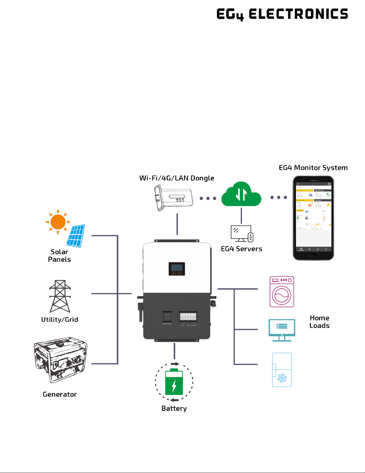
4. BRIEF INTRODUCTION
4.1 INVERTER FEATURES
•Applicable for purely o-grid inverter/backup power situations.
•Integrated with 2 MPPT solar charge controllers with maximum PV input of 480V with an
optimal range of 120VDC-385VDC.
•Additional safety features such as PV Arc Fault Protection and PV Ground Fault Protection.
•Rated for 6kW output, with a power factor of 1.
•Able to run without battery in o-grid mode.
•Able to utilize generators with dedicated generator terminals.
•Supports paralleling for up to 16 inverters.
•Supports CAN/RS485 for Lithium battery communications.
•Features remote monitoring and firmware updates via mobile phone app or monitoring
system website.
7
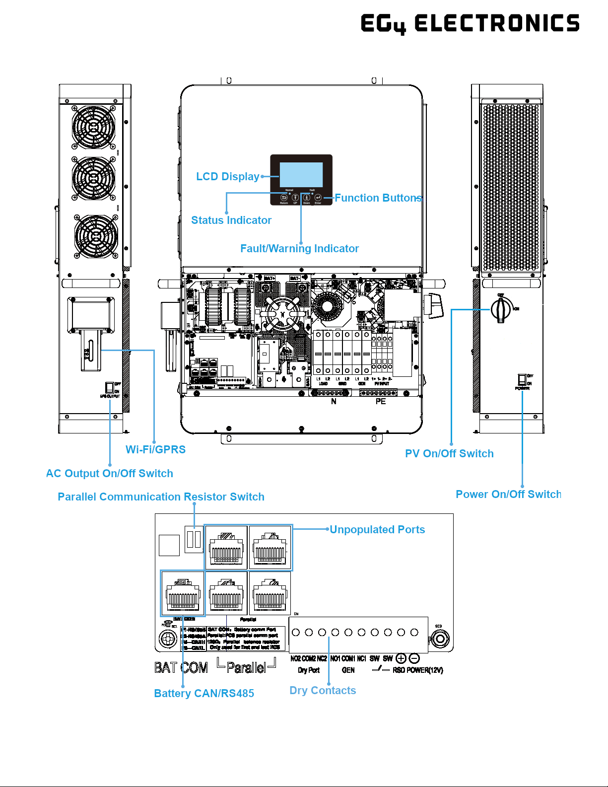
4.2 INVERTER INTERFACE
8
5. INSTALLATION
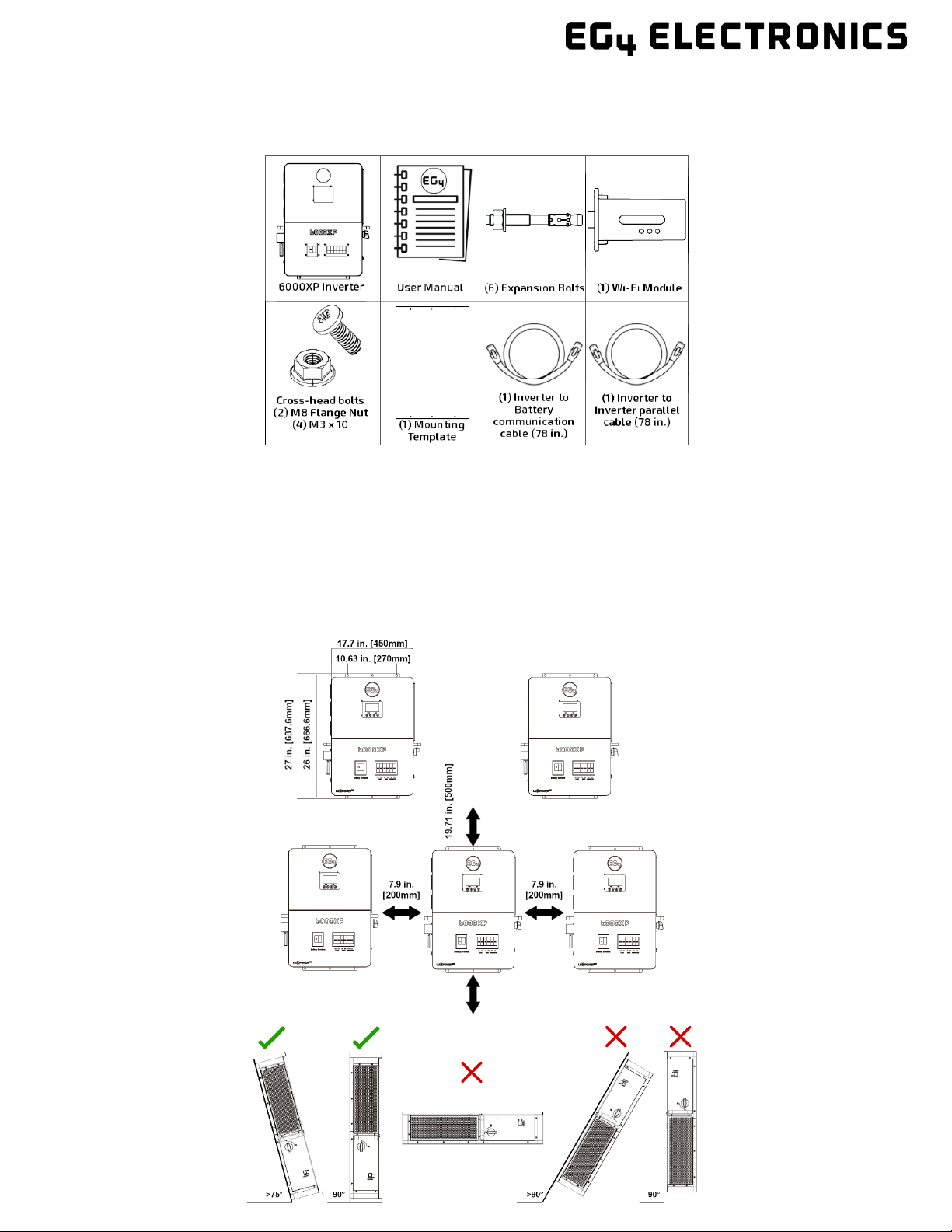
5.1 PACKING LIST
When the product is unpacked, the contents should match those listed below:
Pictures are for reference only, subject to our available products.
5.2 LOCATION SELECTION AND INSTALLATION
1. The mounting wall should be strong enough to bear the weight of the inverter.
2. Please maintain the minimum clearances presented below for adequate heat dissipation.
3. The inverter should be installed upright on a vertical surface.
Inverter Spacing Diagram
Inverter Angle Placement
9
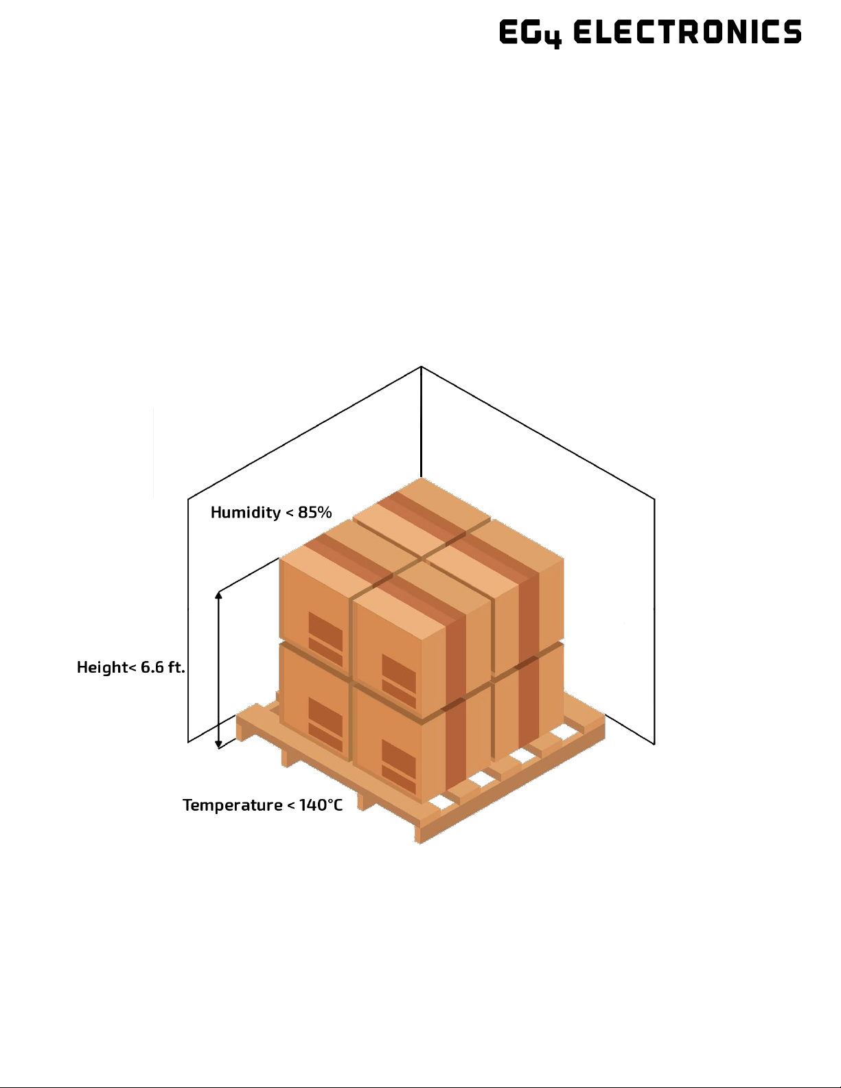
5.3 STORAGE INFORMATION
If placing the inverter into storage before installation, please keep the following factors in mind when
selecting a storage location.
1. The inverter and its components must be stored in its original packaging.
2. The storage temperature should remain within 5 – 140°F (-15 – 60°C), and humidity within 0-
85%.
3. The package should remain upright.
4. Do not store the inverter or its packaging in direct sunlight or where there is potential for water
to accumulate.
5. See diagram below for an example.
10
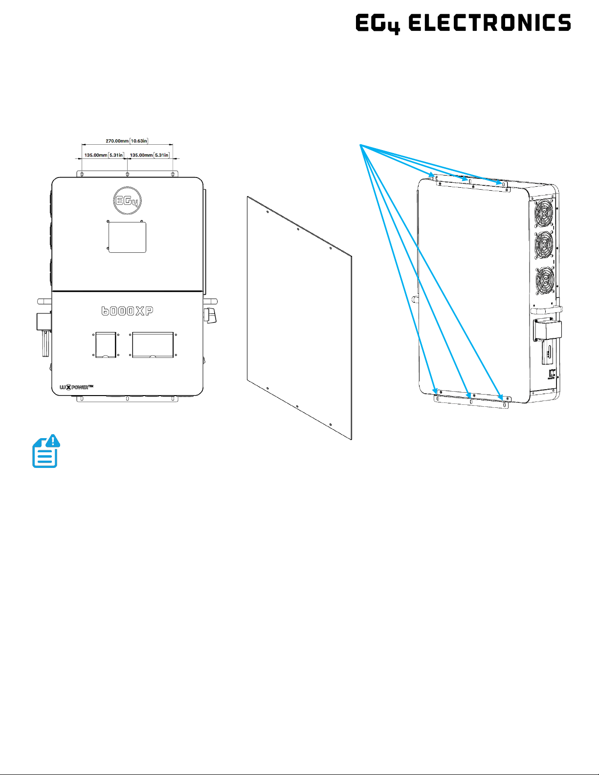
5.3.1 INSTALLING THE INVERTER
The inverter is designed to be wall-mounted and should be installed on a vertical,
solid, mounting surface, such as brick, concrete, or other non-combustible material.
Two or more people may be needed to install the inverter due to its weight (≈53 lbs.).
5.3.2 MOUNTING STEPS
1. Identify where the inverter’s final placement will be.
2. Usethe included cardboard template to mark where the mounting screws will be
installed.
3. Using a ruler, ensure the top left to top right marks are ≈10.63in. apart, along with the
bottom left to bottom right marks.
4. Using a ruler, ensure the top left to bottom left marks are ≈26.2in., along with the top
right to bottom right marks.
5. Place the inverter over the holes to ensure they line up with the bracket plate. Upon
confirmation, proceed to the next step.
6. Drill 5/16 in. (8 mm) diameter holes on the marks, making sure the holes are deeper
than 2 in. (50 mm).
7. Insert the expansion bolts into the drilled holes.
8. Use the corresponding nuts and washers (packaged together with the
expansion bolts) to install and ax the inverter onto the wall. Use the
team-lift technique to ensure the users’safety.
Mounting Template
Mounting Bracket Holes
NOTE:
Ensure the surface the inverter is being mounted to is able to support the
weight of the unit and has proper spacing as per the diagram on the previous page.
11
5.4 CONNECTION OVERVIEW
5.4.1 SYSTEM CONNECTIONS
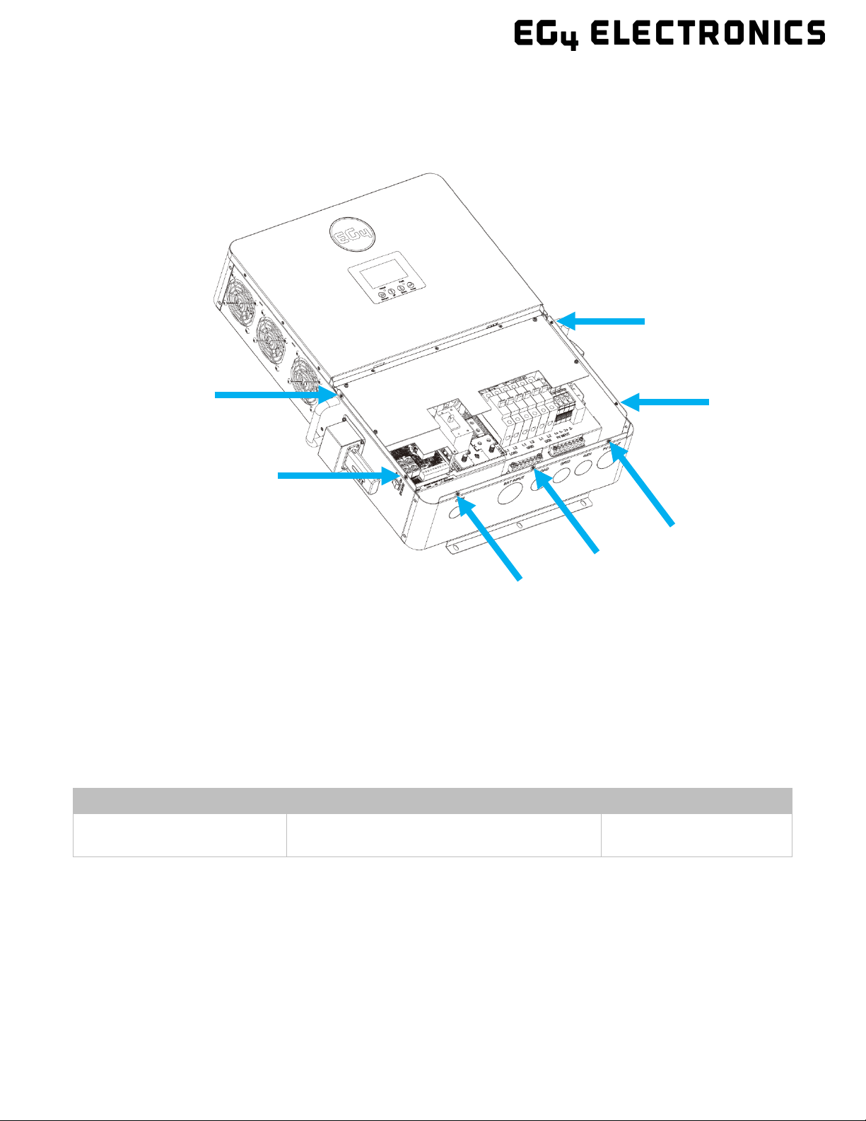
Before connecting wiring, please remove the bottom cover by removing the 7 screws as shown below.
5.5 PV CONNECTION
5.5.1 CONNECTING PV TO THE INVERTER
Install a separate DC circuit breaker/isolator between the inverter and PV module(s). The
recommended DC breaker is a 4-pole 600V/20A, which is the minimum sized isolator switch to house
both positives and both negatives if using two independent strings. If only using 1 string, a 2 pole
600V/20A isolator/breaker is recommended. The recommended cable size for the PV connection(s) is
10 AWG (4mm2) torqued to 10.6 in-lbs. (1.2 Nm).
Consult with the installer to ensure that appropriate cable sizing is used due to various factors such as
voltage drop and Voc.
PV Cable Size Min. PV Disconnect/Isolator Spec Torque Specs
10 AWG – 6 AWG (Max)
(6mm2- 16mm2) 600V/20A 10.6 in-lbs. (1.2 Nm)

12
Verify the lowest ambient temperature of the installation location. The rated Voc on the solar module
nameplate is obtained at STC (Standard Testing Conditions = 77°F/25°C). As the ambient temperature
drops, the solar module Voc increases. Please ensure the maximum solar string voltage, corrected at
the lowest temperature, does not exceed the inverter’s maximum input voltage of 480VDC.
PV Input Data Description Parameter
DC Input Voltage Range Range required for the unit to operate up
to max input 100–480 VDC
Load Output Minimum Voltage Minimum voltage needed to output power
on Load side
>140 VDC
MPP Operating Voltage Range Range where the MPPT can track 120–385 VDC
Nominal MPPT Voltage The MPPT will operate most optimally at
this voltage
320 VDC
Nominal MPPT Amperage The MPPT will operate most optimally at
this amperage
17A
Maximum MPPT Amperage The MPPT can accept up to this amperage
(clipping will occur past this value)
25A
Maximum Utilized Solar Power Wattage the unit can utilize from array
after considering all power loss factors
8kW
5.5.2 STRING SIZING
When solar modules are put in a series string, the voltage multiplies times the number of
modules and the amperage stays the same as each module.
For example: Using solar modules that have a 40VDC Voc (@77ºF) with a Max Power
amperage of 10 Amps (Imp) - 10 modules wired in a series string would have a Voc of 400 VDC
(@77ºF) and a string amperage of 10 Amps. When the temperature lowers, the voltage can
rise above the maximum allowed by the inverter and damage will result.
To determine how many modules per string; first verify the lowest possible ambient temperature of
the installation location. Next, find the rated Voc, Vmp, Isc and Imp of the solar module at 77ºF and the
temperature coecients for voltage and power. Then, calculate highest possible Voc for the entire
string when the ambient temperature falls to the lowest possible ambient temperature upon sunrise.
To make this calculation, use a string calculator or consult a solar designer or solar electrician.
Finally, calculate the maximum current of the string (Isc) so as not to exceed the inverter’s
MPPT circuit ratings of 25A (see note at end of section). Double check if the calculated Vmp
range is within the 120-385 VDC optimal MPPT circuit operating range. It is recommended to
consult a solar designer for assistance.
NOTE:
Each MPPT is rated for 4kW of solar input which leads to 8kW PV input in total.
Size the PV strings accordingly for maximum gain.
CAUTION!
DANGER:
Damage WILL occur if the string voltage exceeds the inverter’s maximum
input voltage of 480VDC!
REMINDER

13
FOR ALL MODULES, THE CALCULATIONS NEED TO BE PERFORMED OR VERIFIED BY USING A
STRING CALCULATOR OR CONSULTING A PROFESSIONAL.
The inverter has two MPPT PV charging circuits. MPPT #1 and #2 will utilize up to 17 amps, which
means two strings can be paralleled for any modules having less than 8.5A (Imp) rating.
When sizing strings for each MPPT, they MUST be the same model, brand and # per string
(series and parallel).
All panels on a series/parallel string should face the same orientation and be exposed to
roughly the same shading across the string. Consideration should be placed on string location
and wiring order on the racking to minimize shading eects. One shaded module will
disproportionately reduce the output of the entire string. This can be mitigated by avoiding
linear strings in favor of rectangular strings, or by the use of string optimizers.
5.5.3 PV WIRING INSTRUCTIONS
Step 1: Before installing PV wiring into the inverter, please ensure all breakers and disconnects are
open (o) and confirm the PV strings are not energized by using a multimeter to ensure there is no DC
voltage on the lines. Once that has been verified, please proceed to step 2.
Step 2: Strip o 1/4 - 5/16 in. (6 – 8mm) insulation from the PV strings’ positive and negative
conductors.
Step 3: Insert the conduit fitting into the openings for the PV connections and tighten from the inside
using the counter nut.
Step 4: Route the PV conductors through the conduit fitting and into the inverter.
Step 5: Secure the PV conductors in place into their respective terminals and torque to 10.6 in-lbs. (1.2
Nm). Verify the cables are secure by lightly tugging on them.
Step 6: Ensure the conduit and conduit fittings are fastened reliably, and the cable entry holes are
sealed.
WARNING: Please follow the steps listed below to ensure proper PV connections.
NOTE: The array may have a higher Imp than the 17A specified, but the MPPTs may
not make full use of the extra current which could lead to component deterioration
over time.
NOTE:
All exposed metal parts of the system must be grounded regardless of
voltage, including solar panel frames.
DO NOT GROUND NEGATIVE PV LINES, ONLY SOLAR PANEL FRAMES!
NOTE:
If using fine stranded wire, use ferrules to secure the connections to the inverter

14
Please see diagram below for PV terminal labeling:
5.6 BATTERY CONNECTION
The EG4 6000XP can utilize either Lithium or Lead-Acid batteries. There is a combination of settings
that need to be configured depending on the battery type.
5.6.1 BATTERY CABLE CONNECTION
Follow the steps below to properly connect the battery wires.
Step 1: Place all breakers in the open (o) position
before connecting or disconnecting wires. Ensure that
there is no DC voltage present with a voltmeter.
Step 2: Assemble battery ring terminal based on
recommended battery cable and terminal size (see
table below).
Step 3: Connect all batteries as the unit requires.
NOTE:
For Lead-Acid batteries, the recommended charge current is 0.2C
NOTE:
If using a battery rack, ensure that
all battery connections are installed
properly before proceeding. Please refer to
battery manual for more information.

15
Step 4: Connect the positive battery cable (Red) to the positive battery terminal (BAT+) and the
negative battery cable (Black) to the negative battery terminal (BAT-) with a torque rating of ≈97 - 106
in-lbs. (11 – 12 Nm) per connection.
Step 5: Be sure not to cross-polarize, as this will damage the equipment.
The recommended battery cable and terminal size are as follows:
*Charging Current: 115A @48VDC (AC), 125A @48VDC (PV)
*Discharging Current: 140A
5.6.2 LITHIUM BATTERY COMMUNICATIONS
Upon successful installation of the batteries, follow the next steps to enable closed-loop
communications (with compatible battery modules) between batteries and inverter.
1. Connect either the CAN or RS485 (depending on make/model of battery) communications cable
between inverter and battery. See diagram below.
2. For the inverter to communicate with the battery BMS, setting 3 must be changed to “Li-io n”.
The inverter will then switch to a secondary setting. Here, select the make/model of battery
and press enter to registersthe change. For EG4 batteries, select “0” after confirming “Li-ion”
as the battery type.
Maximum
Amperage
Battery
Capacity
Wire
Size
Ring Terminal To rq ue
Value
Te r m ina l
Temperature
Rating
Cable
(mm2)
Dimensions
Depth
Length
140A*≥200AH 1 AWG 38 .25 in.
(6.4mm)
1.5 in.
(39.2mm)
97 – 106 in-
lbs.
(11 – 12 Nm)
-40 - +248°F
(-40° - +120°C)
NOTE: The recommended battery capacity of one 6000XP inverter is ≥200AH
ATTENTION: If attempting to BMS communicate with EG4 LifePower4 batteries,
an optional firmware update will need to be performed on the batteries.
NOTE:
If needing to extend the inverter to battery communication cable, or to
build a new one, please refer to the following table for the inverter pinout
descriptions.
16
For battery specific pinouts, please refer to the respective battery user manual.
5.7 AC WIRING INFORMATION
When sizing AC wires, please adhere to the following information.
AC Cable Requirements:
Terminal Connection
Wire Size
Torque Values
GRID
8 AWG (10mm2) 18 in-lbs. (2 Nm)
GEN
8 AWG (10mm2) 18 in-lbs. (2 Nm)
LOAD
8 AWG (10mm2) 18 in-lbs. (2 Nm)
Ground-Neutral Bonding
The information below describes the nature of the ground and neutral in the inverter and
their relationship to the system. Always consult with the installer or alicensed electrician
to ensure that the right configuration is being used:
•The neutral line is asolid connection between AC input and AC output (known as
aCommon Neutral Architecture).
•The neutral line between the AC input and AC output is never disconnected.
•This architecture assumes there is a single neutral-ground bond in the system. Typically, the
neutral-ground bond for a system will be at the first means of disconnect for the grid. However, if
there is no neutral-ground bond in the system, the 6000XP can be configured to create the bond
internally (see setting 26).
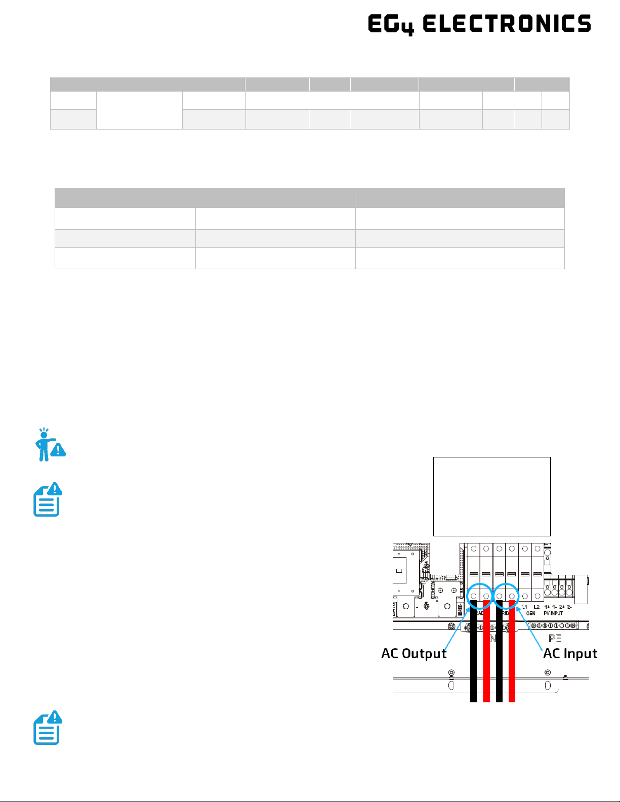
5.7.1 STEPS FOR AC CONNECTION
Please follow the steps outlined below to ensure proper
AC Input/Output connections.
Step 1: Before installation of any wiring, please ensure all
breakers are open (o) before making any connections. Use a
multimeter to confirm the AC Input lines (L1, L2 and neutral) are
not energized.
Step 2: Strip o 5/16-3/8 in. (8-10 mm) insulation from the AC
cables.
Step 3: Fasten the AC Input wires into their respective terminals
using the proper torque ratings.
PIN #
1
2
3
4
5
6
7
8
CAN
Pin
Description
X X X BMS_CAN H BMS_CAN L X X X
RS485
BMS_485 B BMS_485 A X X X
Standard US Wiring
L1 – Black
L2 – Red
Neutral – White
Ground – Green
WARNING: This is not a dynamic bond. It is either always enabled or always disabled.
NOTE: Always be sure to connect the AC Output ground
wire to the Ground terminal bus (labeled PE in the diagram)
first before installing AC Outputs L1 and L2.
NOTE:
After connecting all AC wiring, put the built-in LOAD breaker back to the ON
position before providing power to the load.
If using fine stranded wire, use ferrules to secure the connections to the inverter.
Other manuals for 6000XP
1
Table of contents
Other EG4 Inverter manuals


Popular Inverter manuals by other brands


Emerson
Emerson BMS 404 030/2+ operating manual

Mitsubishi Electric
Mitsubishi Electric FR-F806-E Hardware instruction manual

Northern Lights
Northern Lights L944D, M944W, NL944D2, M30CW, M944T, NL944T2, and... Operator's manual

Bosch
Bosch Servodyn-D Series manual

Coleman
Coleman CM04143N Operator's manual

Mastervolt
Mastervolt WHISPER 9 installation manual