Stratix eZ-2D Xaminer Installation and operation manual

6/17/2015
STRATIX XAMINER EZ-2D BARCODE VERIFIER |
PRODUCT REFERENCE GUIDE (V2.0)

1
Table of Contents
Chapter 1 Getting Started ...................................................................................................... 2
Unpacking......................................................................................................................................2
System Requirements.....................................................................................................................2
Installing the Verifier......................................................................................................................2
Placing the Barcode Symbol............................................................................................................5
Chapter 2 Using the Verifier................................................................................................... 9
Looking at Data with the Verifier ....................................................................................................9
Commanding the Verifier .............................................................................................................10
Verifier Toolbar Button Commands...............................................................................................11
Symbol Image Window.................................................................................................................13
Symbol Grades Window ...............................................................................................................14
Symbol Statistics Window ............................................................................................................16
Chapter 3 User Preferences Options .................................................................................... 17
Accessing the Parameter Setup Window .......................................................................................17
Symbol Grades Setting .................................................................................................................21
Chapter 4 GS1 Data Structure Validation.............................................................................. 22
GS1 Data Structure Validation Overview .......................................................................................22
GS1 Application Identifier Details .................................................................................................22
GS1 Data Structure.......................................................................................................................23
Chapter 5 Exporting Reports ................................................................................................ 24
Exporting Reports to Excel............................................................................................................24
Exporting Reports to Adobe PDF File.............................................................................................25
Chapter 6 Error Messages .................................................................................................... 28
System Error Messages.................................................................................................................28
Scanner Reset ..............................................................................................................................30
Appendix A: 2D Barcode Samples ........................................................................................ 31

2
Chapter 1 Getting Started
Unpacking
Before going any further, take a moment to check the contents of the package to ensure your order was shipped
complete. Make sure no items are damaged or omitted. Xaminer eZ-2D verifier package includes:
Carry case
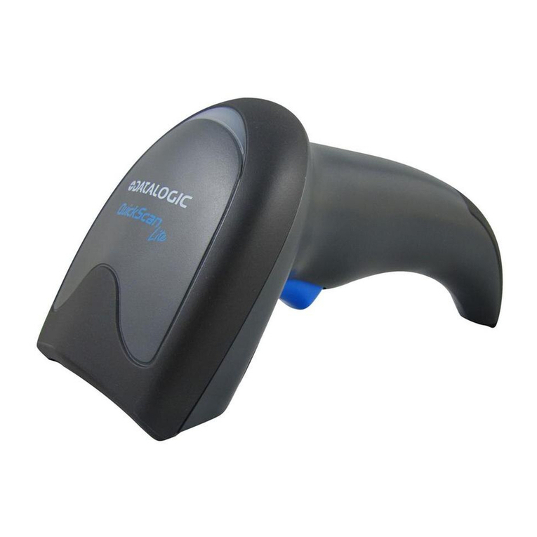
Imager scanner & USB interface cable
Stand
Calibration files CD1
Verifier software and imager scanner driver CD2
Installation guide
Product reference guide
Calibration Check Card
Certificate of Calibration
If any of these items are missing or damaged, please notify Stratix Corporation within two business days of receipt
of your verifier.
System Requirements
Windows® 7 (32 bit/64 bit), Windows® 8 (32 bit/64 bit).
Intel® Core™2 Duo Processor.
2GB of RAM.
USB port 2.0.
Microsoft.NET Framework 4.0 or later
Microsoft Visual C++ 2010 Redistributable Package (x86)
Microsoft Office Excel, Microsoft Internet Explorer.
Adobe Reader.
Installing the Verifier
1. Plug the USB cable modular connector into the cable interface port on the bottom of the imager scanner
handle. See Figure 1-1.
2. Gently tug the cable to ensure the connector is properly secured.
3. Connect the other end of the interface cable to the PC USB port.
4. Place the verifier stand on a flat desk surface.
5. Place the imager scanner into the scanner holder (cup). See Figure 1-2.

3
Figure 1-1
Figure 1-2

4
Stand Position & Field of View (FOV)
Stand position 1: Stand position 1 is the primary verification position for most barcodes. The FOV at this position is
1.10” x 1.10”(Figure 1-3 white square), and the maximum barcode size is 1.0” * 1.0”. The minimum X dimension
required for the barcode is 10mils.
Stand position 2: Stand position 2 is used for bigger barcode which the FOV at stand position 1 is too small for the
barcode to be verified. The FOV at stand position 2 is 1.30” x 1.30” (Figure 1-4 white square), and the maximum
barcode size is 1.2” * 1.2”. The minimum X dimension required for the barcode is 15mils.
Note: The illuminated red brackets and the red crosshair on the surface of top plate are the aiming pattern of
imager scanner. The relative position between the crosshair and FOV is useful for better placing the barcode in the
center of the FOV.
Figure 1-3 Stand Position 1 FOV

5
Figure 1-4 Stand Position 2 FOV
Placing the Barcode Symbol
1. Extract the plunger (Figure 1-5) and move the top plate up or down to stand position 1 or 2, and then
insert the plunger into the hole of that position (Default is stand position 1).
2. Loosen the knob to move down the bottom plate to make enough room for placing the barcode item
between top plate and bottom plate.
3. Place barcode item on the surface of bottom plate, make sure the barcode symbol faces the top plate.
4. Move the bottom plate up once it reaches the top plate.
5. Adjust the barcode position to ensure it is in the center of the FOV.
6. Tighten the knob to make it ready for verifying.

6
Figure 1-5 (a)
Figure 1-5 (b)

7
Supported Barcode Symbologies
Stratix Xaminer eZ-2D supports two barcode symbologies: QR Code and Data Matrix (ECC 200).
QR Code: The minimum symbol size is 21X21, and the maximum symbol size is 57X57. See Figure 1-6.
Data Matrix: The minimum symbol size is 10X10, and the maximum symbol size is 52X52. See Figure 1-7.
Figure 1-6(a) Figure 1-6(b)
Figure 1-7(a) Figure 1-7(b)

8
Opening Verifier Software
To open Stratix Xaminer eZ-2D, click the Stratix Xaminer eZ-2D icon (Figure 1- 8) on your desktop, or open the
Start Menu and click on All Programs->Stratix Corporation->Stratix Xaminer eZ-2D.exe (Figure 1-9)., the main
user interface will open.
Figure 1-8
Figure 1-9

9
Chapter 2 Using the Verifier
Looking at Data with the Verifier
The first time you open Stratix Xaminer eZ-2D you will see the three data windows shown below (Figure 2-1).
Verification reports are displayed in these windows (Figure 2-2) by commanding the Stratix Xaminer eZ-2D to scan
barcode using this interface.
Figure 2-1

10
Figure 2-2
Commanding the Verifier
The imager scanner is controlled from the Stratix Xaminer eZ-2D interface with three principal selections: Aiming,
Scan, and Auto Scan.
Aiming: To center a barcode in the FOV of the half circle bracket, click the Aiming button. This will project the laser
beam from the imager scanner.
Scan: To scan a barcode, click the Scan button. The scan results will immediately be displayed in the three data
windows.

11
Auto Scan: The auto scan feature allows data to be collected in batches. This feature is useful for quickly
generating average grades based on multiple scans for a single barcode.
To use Auto Scan:
1. Click the Auto Scan button.
2. The Auto Scan window will be displayed (Figure 2-3).
3. Set the number of scans required in the field labeled Total scan number to perform.
4. Click Start to begin scanning the barcode. When the requested number of scans has been completed the
operation will end automatically.
5. Completed scans can be viewed by clicking the List button.
Figure 2-3
Verifier Toolbar Button Commands
The Toolbar features button commands that allow you to quickly and easily access and view verification reports.
List: The List button displays a scan report tree on the left side of the main window that contains each verification
scan that has been completed. New reports will be appended to any existing reports already in the file.

12
Open: The Open button opens a saved Stratix Xaminer eZ-2D verification report file.
Save: The Save button saves all of the stored verification reports.
Previous or Next: The Previous or Next button reviews any of the stored verification reports.
Delete: The Delete button deletes the current verification report.
Empty: The Empty button deletes all of the stored verification reports.
PDF: The PDF button creates a PDF file for the current verification report.

13
CSV: The CSV button creates a Microsoft Excel CSV file for all of the stored verification reports.
GS1 Structure: The GS1 Structure button displays GS1 Data Structure for the current verification report.
WWW: The WWW button lunches Internet Explore Brower which the URL is embedded in the barcode of the
current verification report.
Symbol Image Window
Symbol image window (Figure 2-4) provides the symbol position in the field of view and stand position 1 or 2 which
is displayed on the title bar of this window. Be sure the symbol is within the red circle area. The two green circles
are used for better position the barcode in the center of the field of view.
Figure 2-4

14
Symbol Grades Window
Symbol grades window (Figure 2-5) provides the symbol data for the barcode and displays the Symbol verification
results for the currently selected report. User may click the “List” button on the toolbar to display any verification
results of all the reports in the current session.
Figure 2-5 (a) QR Code Report

15
Figure 2-5 (b) Data Matrix Report

16
Symbol Statistics Window
Symbol Statistics window (Figure 2-6) provides cumulative measures on certain parameters for all the reports in
the active file. The measures provided are Min/Max/Delta and Average for all scanned reports. The Statistics
parameters including:
Unused Error Correction
Axial Non Uniformity
Vertical Print Growth
Horizontal Print Growth
Figure 2-6

17
Chapter 3 User Preferences Options
Accessing the Parameter Setup Window
Go to the Tools pull down menu, select Parameter Setup, the Parameter Setup window is displayed (Figure 3-1).
Use this window option to setup:
Stand Position
Analysis Mode
Sample/User/Job ID
Miscellaneous
Stand Position Setting
1. Select tab Stand Position (Figure 3-1)
2. Choose 1 or 2 for stand position (Default is 1).
3. Click OK or Apply button to complete the setting.
Figure 3-1
Analysis Mode Setting
1. Select tab Analysis Mode (Figure 3-2)
2. Choose A, B, C, D or F for Symbol Pass On grade (Default is C).
3. Choose Positive (dark on light) or Negative (light on dark) for Symbol Style (Default is Positive).
4. Click OK or Apply button to complete the setting.

18
Figure 3-2
Sample/User/Job ID Setting
1. Select tab Sample/User/Job ID (Figure 3-3)
2. Enter the desired Sample ID, User ID, and Job ID
3. Click OK or Apply button to complete the setting.
Figure 3-3
Miscellaneous Setting
1. Select tab Miscellaneous (Figure 3-4)
2. Select desired average scan number in the field labeled Average Scan #.
3. Enable/Disable imager scanner beeper by check/uncheck Scanner Beeper (Default is enable).
4. Enable/Disable calibration reminder by check/uncheck Calibration Reminder (Default is enable).
5. Click OK or Apply button to complete the setting

19
Figure 3-4
Factory Reset
1. Go to the Tools pull down menu, select Factory Reset, the Factory Reset window is displayed (Figure 3-5).
2. Click Yes button to perform factory reset that will fully restore the factory parameter settings.
Figure 3-5
Calibration Check
1. Go to the Tools pull down menu, select Calibration Check, the Calibration Check window is displayed
(Figure 3-6).
2. Click Start button to start the calibration check. If the calibration check continues to be failed after several
attempts, contact Stratix Customer Support at 1-800-883-8300 to arrange the return of your verifier for
recalibration.
Table of contents

