Page 16 11/07/00
3.1 RECOMMENDATIONS FOR THE USER
•Keep this booklet with care near the appliance for any fur-
ther consultation.
•For good working and validity of the guarantee, ask for
the unit to be serviced annually by a qualified engineer.
•All the installation operations have to be made exclusively
by professional qualified people in respect of the safety
regulations in force. An incorrect installation, caused by
not observing the manufacturer’s instruction can cause
damage to people, animals or things for which the manu-
facturer can not be considered responsible.
•The appliance has been manufactured for hot water pro-
duction: any other use of it has to be considered dangerous
and not suitable.
•The appliance is not to be installed in damp rooms; it has
to be protected from water splashes and other liquids, to
avoid anomalies to electrical and thermal devices.
•Installation has to be carried out by professional qualified
people according to the safety regulations in force.
•Packaging parts (i.e. plastic bags, polystyrene, wood,
clips, nails etc.) can be harmful to children and should be
carefully disposed of immediately.
•Read carefully the instructions and the advice contained in
this booklet concerning safety, installation, use and main-
tenance.
•If the appliance is sold or transferred to a new owner,
make sure that this booklet stays with the appliance, so
that the new owner or installer can consult it.
•Do not place anything upon the appliance.
•To avoid damages caused by low temperatures, if the ap-
pliance has to be left unused for a long period in a non-
heated room, it is recommended the unit is drained com-
pletely.
•The manufacturer is not responsible for faults, break
downs or for water leakage from the plant caused by low
temperatures.
•To get the best efficiency of the appliance and to comply
with the guarantee, we advise you to adhere to these in-
structions, to have the appliance checked by professional
qualified people and to use only original spare parts and
kits supplied by the manufacturer.
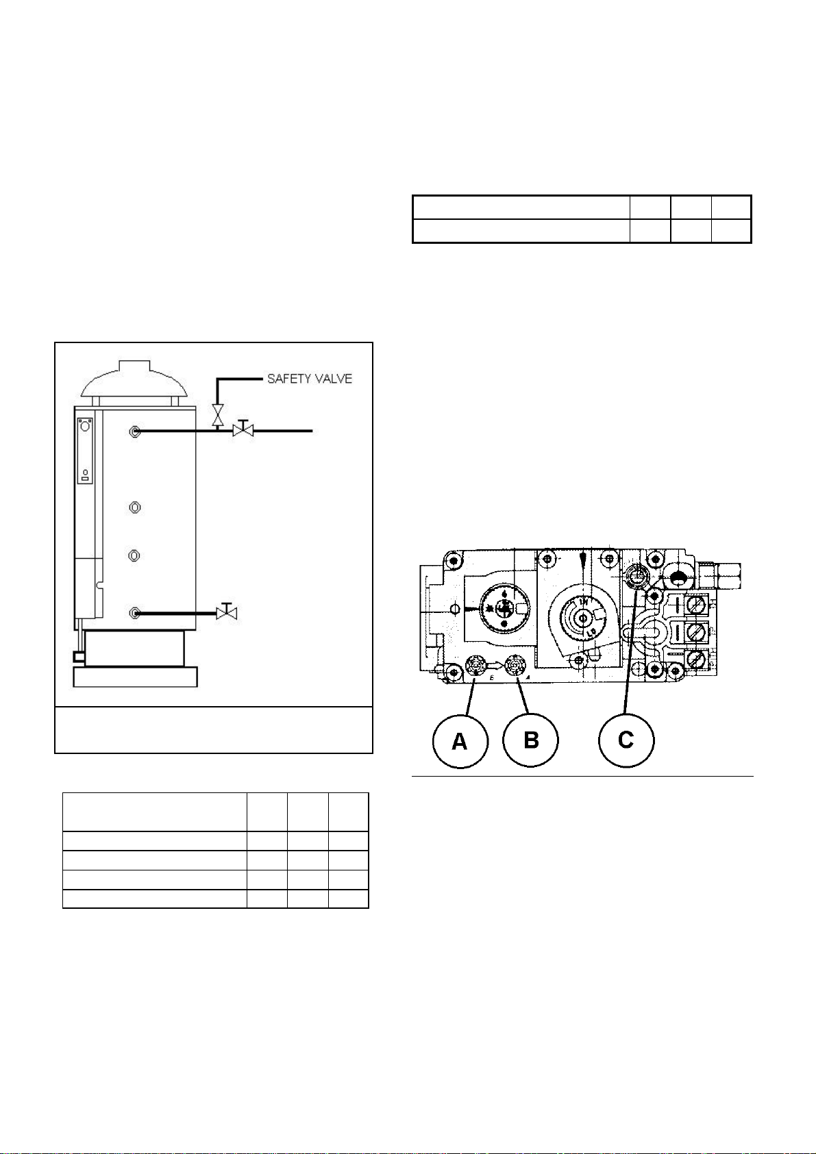
3.2 STARTING THE APPLIANCE
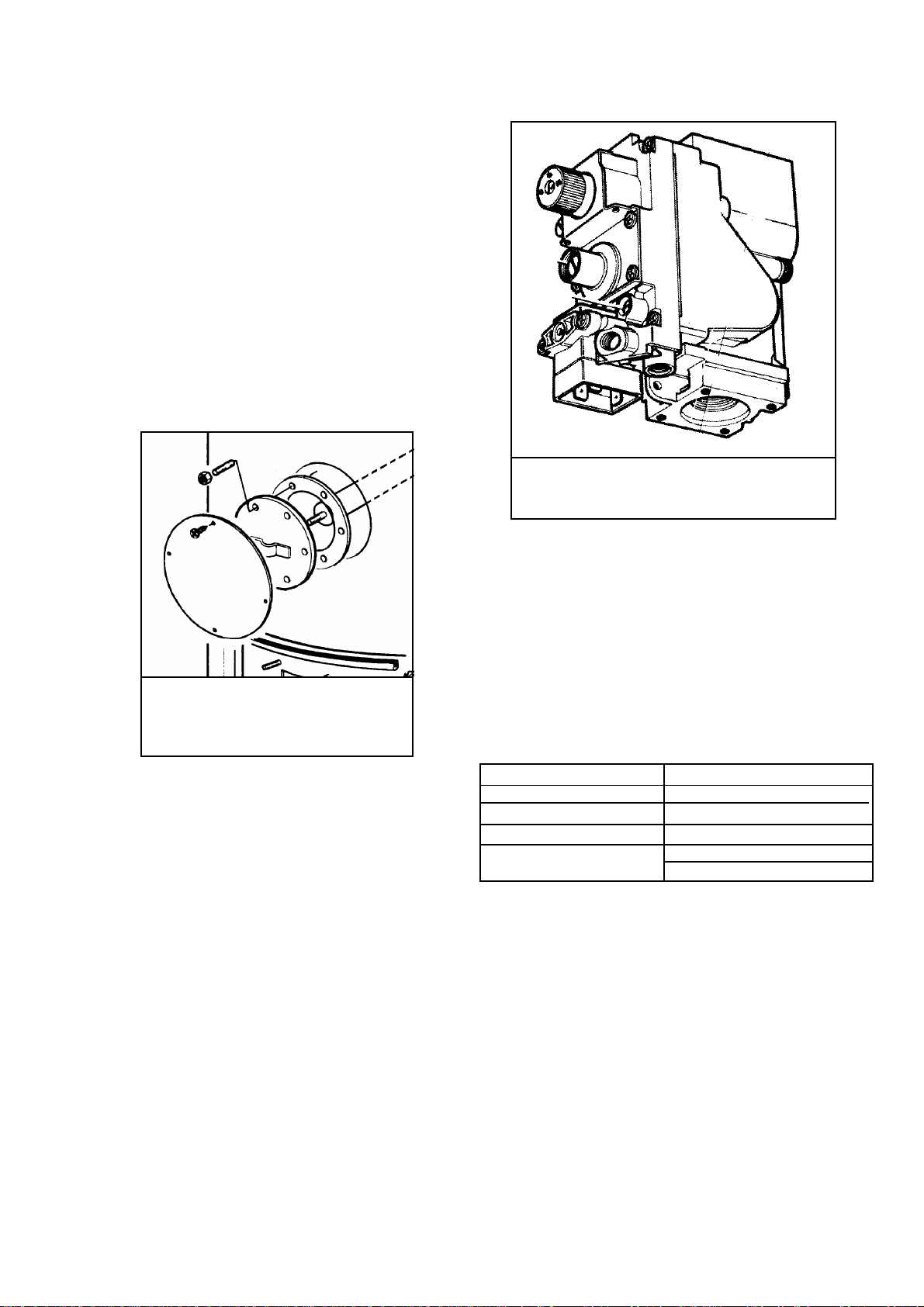
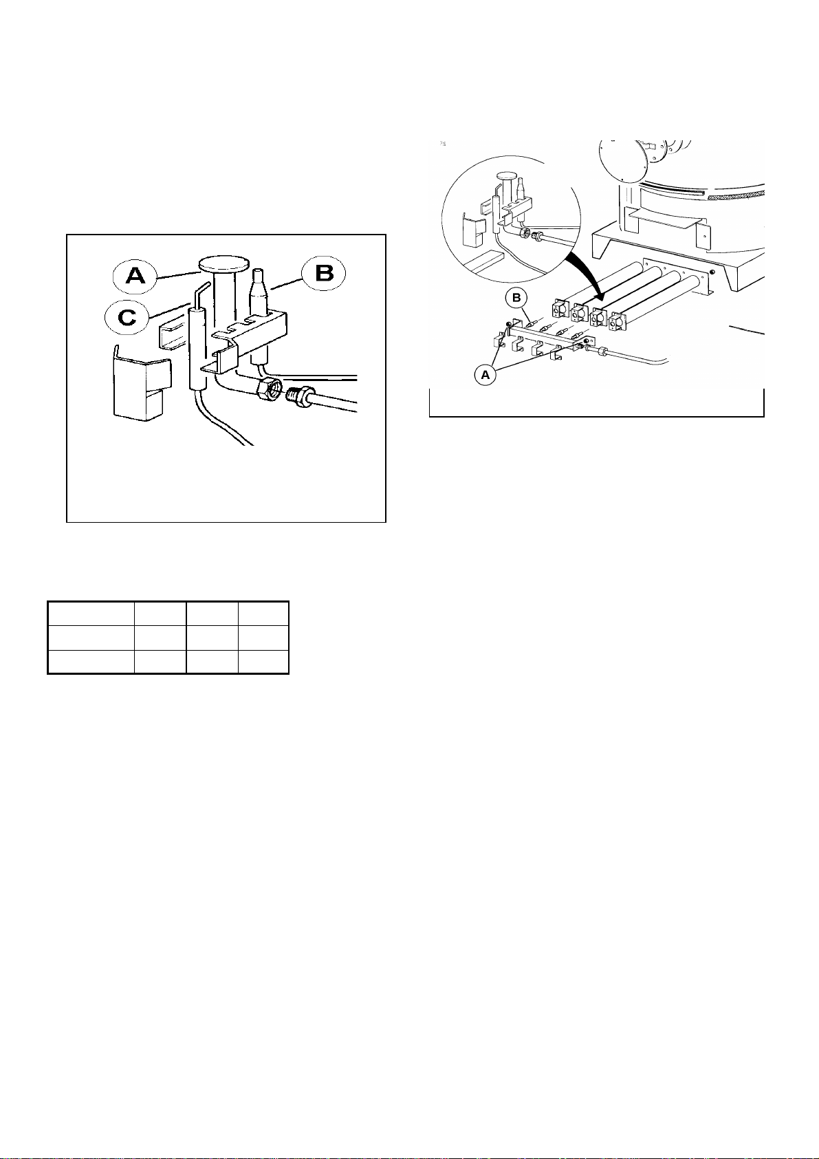
1. PILOT FLAME IGNITION: push and turn the knob of the
gas valve in the pilot position; push the knob and light the
burner through the piezo-electric ignition on the valve.
Keep the knob pushed for some seconds, and leave it by
checking that the pilot burner flame is established. Repeat
if the pilot flame extinguishes.
2. PRINCIPAL BURNER IGNITION: push and turn the
knob to the On position.
3. set the switch on the ON position “I”;
4. set the control thermostat indicator to the desired water
temperature (min. 40° max. 70°).
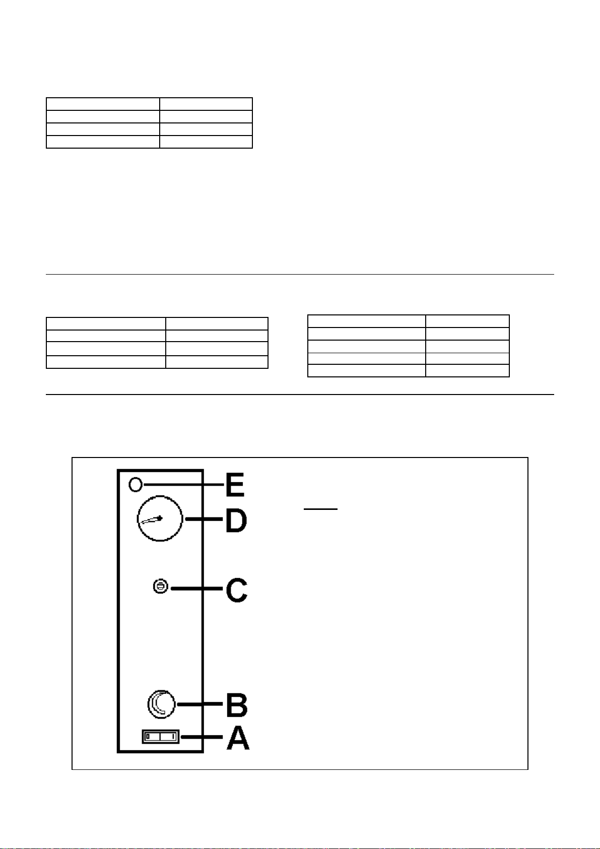
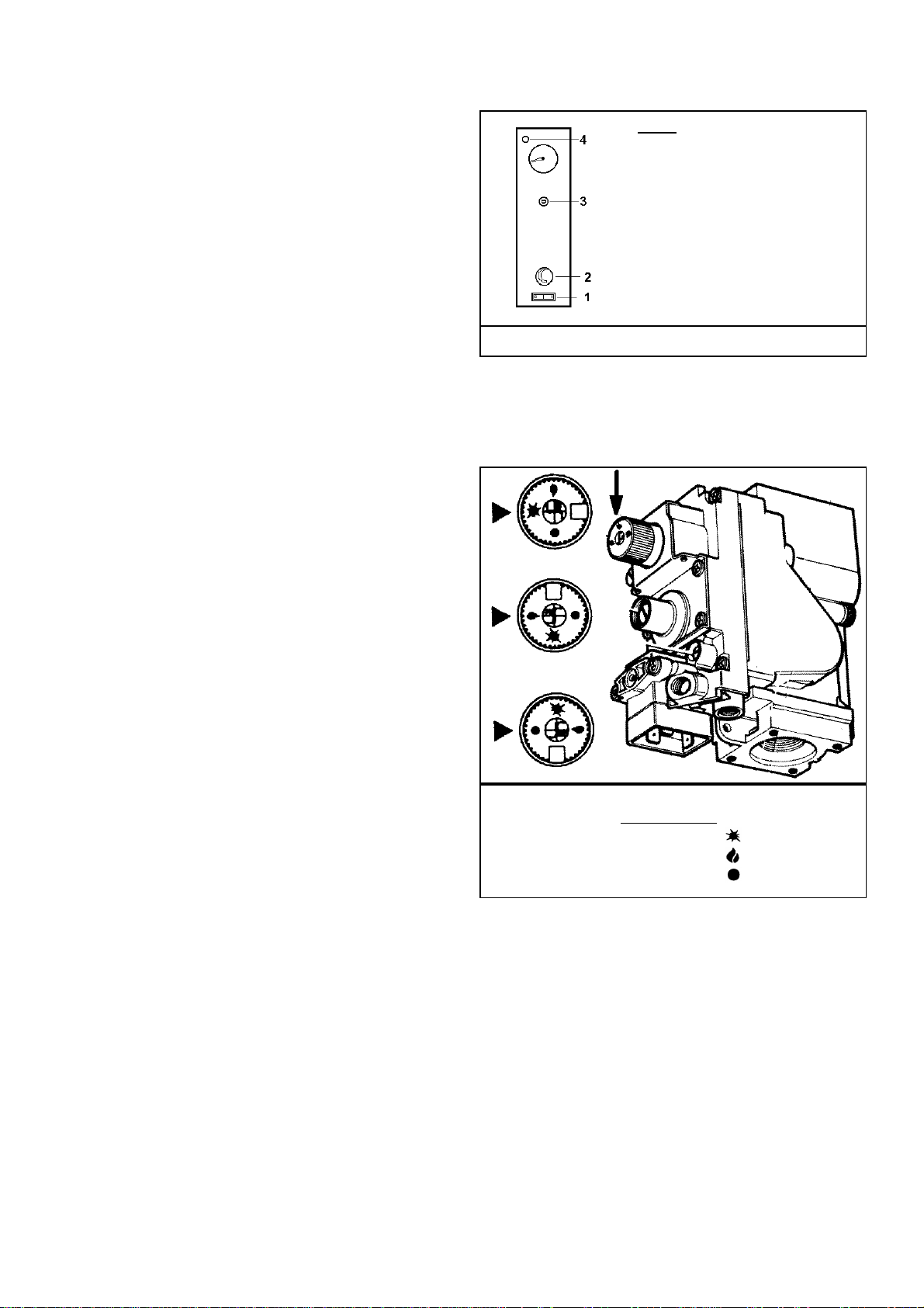
Fig 3.2 / 1
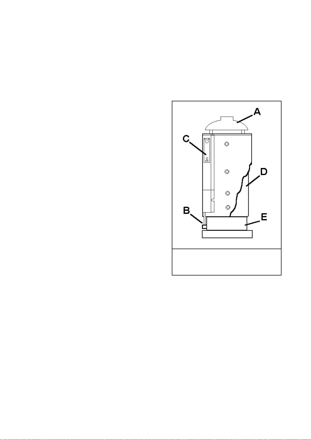
KEY:
1 –ON/OFF Switch
2 –Water temperature thermostat
3 –Safety limit thermostat
(exhausting gas)
4 –Safety limit ther
light
To check the operating of the thermostat, turn the knob 2
(pict. 3.2/1) to the lower value and check that the burner ex-
tinguishes. Turn the knob again to the previous pre-set value
and check for a proper ignition of the burner.
From this moment on the water heating phase begins: the
burner will operate until the water temperature reaches the
temperature set at point 2: at this moment the principal
burner switches off (the pilot burner remains alight); the
burner will operate again if the temperature goes below the
pre-set value (i.e. a lot of hot water is used).
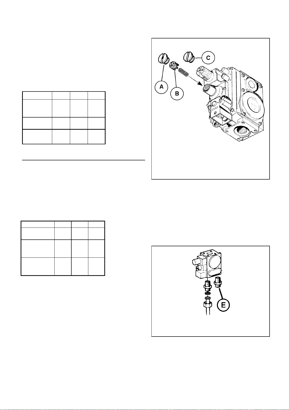
FLUE GAS SAFETY OPERATING: the appliance has a
flue gas spillage thermostat which operates in case of im-
proper exhausting of the combustion gases (i.e. if the chim-
ney is blocked). If this happens, the red light (4) will be illu-
minated and the gas supply to the principal burner is
stopped. To reset push the button under the cover cap plug
(3) in order to restart again the appliance.
Fig 3.2 / 1
Gas valve knob
Position: PILOT
ON
OFF