STROMBERG e-FIRE User manual

STROMBERG e-FIRE OWNER’S MANUAL
8BA MODELS
Made by Stromberg in England
SSP 9018V1
If you need further information
or assistance, please contact
your Stromberg dealer,
or e-mail us direct at:
tech@stromberg-97.com
or log on to our Tech Center at:
stromberg-97.com

THANK YOU
for choosing a Genuine Stromberg e-FIRE
electronic distributor for your Flathead Ford.
This Owner’s Manual will make installation and
adjustment as safe and trouble free as possible.
It contains several warnings, cautions and notes.
Please read them all. It also includes important
information about the Stromberg warranty and
what to do if you need help.
If you experience any difficulties with distributor
installation & timing, please check the detailed
Troubleshooting section of this manual first.
There is help available at the Stromberg Tech
Center: www.stromberg-97.com. And you can
contact us direct: tech@stromberg-97.com
WARNINGS AND NOTES:
These instructions must be read and fully understood
before beginning installation, otherwise installation
should not be attempted. Failure to follow these
instructions, including illustrations, may void your
warranty and could result in poor performance, vehicle
damage, property damage, severe personal injury or
death. If you need information or assistance, please
contact your Stromberg dealer or email us direct:
tech@stromberg-97.com
WARNING:
Correct distributor installation and set up is critical
to engine performance, so a thorough knowledge of
vehicle mechanical and electrical systems is required.
Stromberg recommends installation by a professional
mechanic only. An improperly installed or adjusted
distributor may void your warranty and may cause poor
engine performance or damage, property damage,
personal injury or death.
WARNING:
This e-FIRE distributor (12v negative or 6v positive
ground) should be used with a 1.5 Ohm (Ω) coil. Coils
with a higher Ohm rating (often called ‘internally
resisted’) will reduce power to the ignition module
leading to unreliable performance. Remove or bypass
any external ballast resistor or resistor wire. If your
engine has a starter bypass wire, you can leave it in
place. DO NOT use a low resistance or HEI coil. A coil
with LESS than 1.5 Ohms resistance could cause
the ignition module to overheat, misfire and fail
prematurely. This will invalidate the warranty.
WARNING:
This distributor is not designed for use with engines
or transmissions requiring computer-control. Use
with these applications may cause damage. This
distributor is not designed for MARINE or AIRCRAFT
applications.
NOTE: This product is legal only for use off-road or
on pre-emission controlled motor vehicles/
engines. In the USA, this means pre-1966
domestic vehicles certified to California
standards, pre-1968 domestic vehicles
certified to federal standards and all
pre-1968 foreign vehicles.
WARNING:
Before installation, please verify that the vehicle’s
electrical system is in good working order. This includes,
but is not limited to, spark plugs and plug wires, battery,
battery cables, generator or alternator, starter, starter
solenoid and its wiring. Any damaged or improperly
operating components can cause additional resistance
in the circuits and must be replaced prior to installing
the distributor. Failure to do so may result in poor
performance, and could cause a fire resulting in property
damage, serious personal injury or death.
READ THIS FIRST
1. PRE-INSTALLATION CHECKLIST
A) Inspect your new Stromberg e-FIRE distributor
for possible shipping damage. Check you have
the correct model for your application. Model
details are clearly marked on the distributor
packaging and ID plate.
WARNING:
DO NOT proceed unless your vehicle’s electrical
system matches that clearly marked on your
new e-FIRE distributor. The wrong polarity will
cause the e-FIRE ignition module to fail and void
your warranty.
B) Stromberg recommends the use of a traditional,
points style 1.5 Ohm ignition coil for both 12v and
6v e-FIRE distributors. That’s 1.5 Ohm primary
resistance measured across the low tension
positive and negative terminals. 1.5 Ohm coils
are sometimes called 6v or 9v coils, though in
practice, ignition coils are not designed for a
specific voltage input. Please refer back to the
previous page for further advice.
C) With a 12 volt e-FIRE model, battery voltage
measured at the coil’s positive terminal with the
engine running, must not exceed 14 volts at any
RPM level. With a 6 volt model, aim for no more
than 8 volts in the charging circuit, under no
load (ie. no lights, no heater etc.)
WARNING:
Excessive voltage can lead to overheating and
ignition module failure.
D) DO NOT use solid core (typically copper) spark
plug wires, which lack resistance and do not
suppress Electromagnetic/Radio Frequency
Interference (EMI/RFI) which can damage the
e-FIRE ignition module. Stromberg recommends
e-FIRE suppression style high performance spark
plug wires.
E) Unlike a points distributor, electronic ignition
needs a reliable, independent power feed and
quality ground (earth) connections. On 6 volt
models, choose a power source as near to
the ignition key as possible. Check all ground
connections and even run an additional engine
ground if required.
1
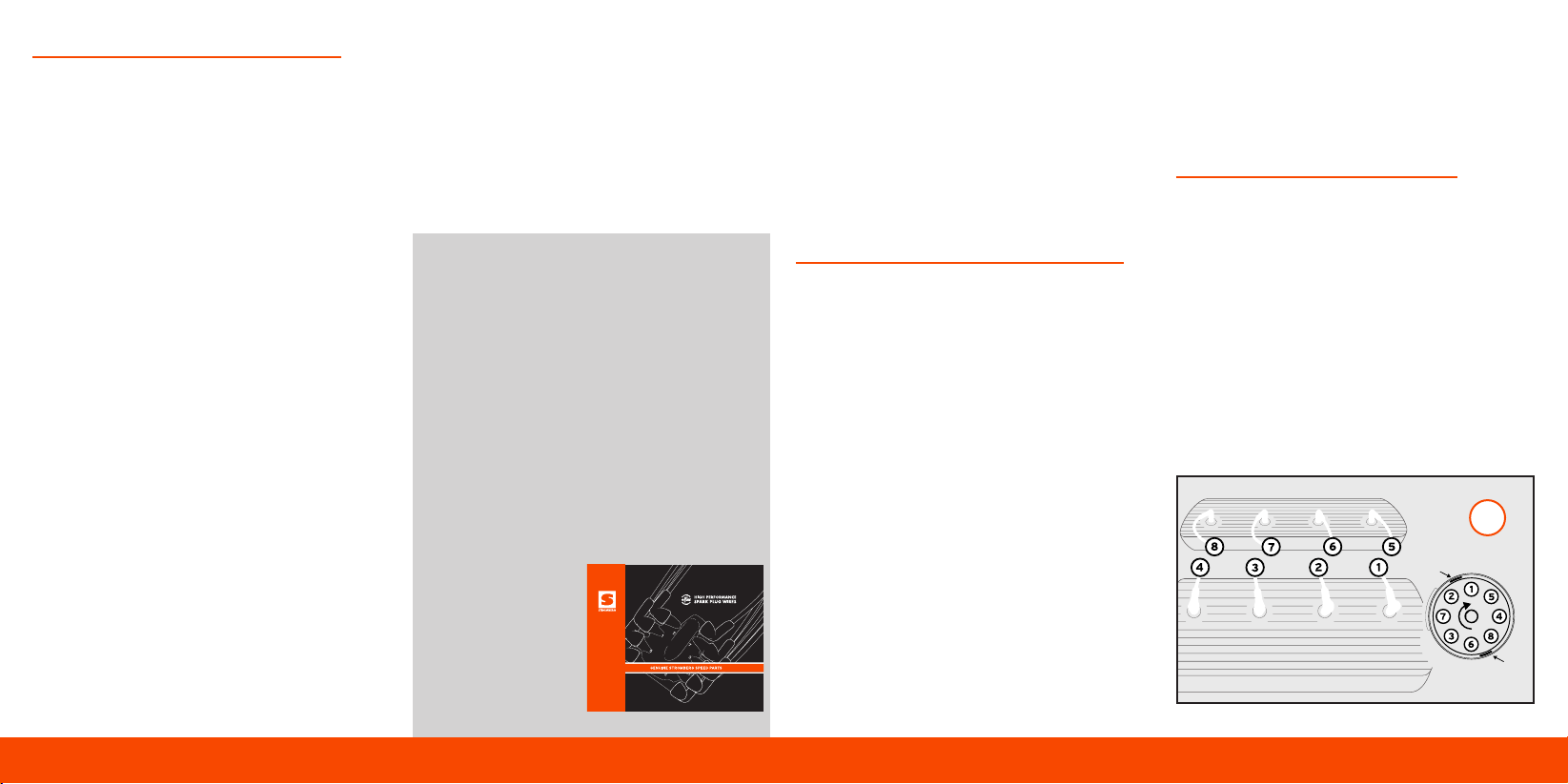
USE E-FIRE HIGH PERFORMANCE
SPARK PLUG WIRES.
Designed for optimum performance with your e-FIRE
electronic distributor, Stromberg e-FIRE spark plug
wires mix strong fire power with high level RFI/EMI
resistance. The spiral-wound, stainless steel
suppression core is protected by tough fiberglass
reinforcing braid for strength and flexibility. And the
100% silicone insulation resists high temperatures,
moisture, oil and chemicals, and protects against
arcing and voltage leaks. With low 500 Ohm/ft
resistance, they get more energy into your plugs too.
For easy installation, the 90-degree cap terminals
and boots are pre-fitted for smarter ‘distributor
first’ installation. This also leaves you free to use the
supplied 90-degree spark plug boots or choose your
own hot rod terminals. All leads are designed to fit
through your flathead
plug wire looms or
tubes, and they’re cut
to length, too, with an
extra-long coil wire
to reach your firewall.
2
F) This e-FIRE distributor fits all of the different
Ford 8BA front covers (distributor mounts). If it
is too tight and the flange won’t sit down onto
the cylinder head, the hole might be rusted or
corroded, so open it out to the OE spec - 3/4in
(19mm). Please note that the slot in the end
of the shaft is used for Stromberg in-house
assembly and pre-ship testing only. Every e-FIRE
distributor is machine tested before boxing to
check timing and high tension function to the
spark plugs.
2. REMOVE EXISTING DISTRIBUTOR
A) Disconnect the vehicle’s battery. Remove the
condenser and any radio suppressors. They are
not required, nor compatible with the Stromberg
e-FIRE distributor. Disconnect the distributor low
tension wire at the coil.
WARNING:
Always disconnect your vehicle’s battery, making
sure the ignition is off and the engine is cool before
performing any work. Failure to do so may result
in sparks or burns, and cause a fire or explosion,
resulting in property damage, serious personal
injury or death.
B) If you are replacing the original Ford Loadomatic
distributor, carefully disconnect the vacuum
advance line at the distributor and carburetor.
It is not required by the e-FIRE distributor. Plug
the vacuum line port in the carburetor.
C) Disconnect the spark plug wires from the
distributor cap. To make replacement easier
on the new distributor, label each wire with its
destination cylinder number.
D) Remove the cap from the original distributor
and make a note or mark where the rotor points
BEFORE removing the distributor from the
engine. THIS IS VERY IMPORTANT! Take a photo!
Now remove the clamp and the old distributor
from the engine.
3. INSTALL NEW DISTRIBUTOR
A) If you are simply replacing another distributor,
smear the drive gear with a little engine
assembly lube and install the new e-FIRE
distributor into the 8BA timing cover engaging
the drive gear into the camshaft gear so that
the rotor points in the same direction as your
old one did (you marked it, remember?). As the
distributor seats down onto the head, the rotor
will spin clockwise as the gears engage, so you
will need to start further counter-clockwise
(about 40 degs) to end up in the right spot.
B) If you are building a new engine, crank it to
Top Dead Center on the compression stroke of
Number One cylinder (See A) and install the new
CLIP
CLIP
A

e-FIRE distributor with the rotor pointing
to your Number One plug terminal on the
cap. We recommend the Ford Service Manual
designated Number One as shown in A. If your
engine has a timing mark, crank the engine
until the pointer lines up with the mark on the
crank pulley on the compression stroke.
C) Install the bolt, spring washer and clamp
(See B). Do not overtighten the bolt. Check
that the distributor flange sits flat on the
mounting surface.
D) Connect the spark plug wires following the
correct firing order and cylinder positions (See
A). The distributor turns clockwise.
E) 12 volt negative ground e-FIRE distributors have
red and black low tension wires. Connect the
black wire to the negative ( - ) side of the ignition
coil. Connect the red wire to the positive ( + )
side of the ignition coil or other power source
controlled by the ignition switch (See C).
3
CLIP
CLIP
B
C
D
F) If your ignition has a primary circuit ballast
resistor or wire, connect the red wire to the
ignition switch side of the ballast resistor (See D).
If the position of the ballast resistor or wire is not
known, connect the red wire direct to the ignition
switch or to a switched live on the fuse box - on
the key side of the fuse.
G) On a 6 volt positive ground model, remove the
ignition switch (power) wire from the negative
( - ) coil terminal and connect the black module
wire to the same negative terminal. Connect the
white wire to that ignition switch power wire. DO
NOT attach the white wire to the ignition coil.
(See E). Connect an insulated AWG 20 copper
stranded wire from the positive coil terminal
direct to a good quality chassis ground.
Note: Most early Ford 6 volt positive ground coils were
ballast resisted. If possible connect the white module
wire to the switched ignition side of the resistor (often
located under the dashboard).
H) Terminals are supplied. Use standard auto wire
- 20 gauge (1.5mm) 15 amp – to lengthen any
wires. Crimp tightly or solder (best) the joints and
insulate all connections. Do not pull on the wires
causing them to tighten inside the distributor
cap. The wires must allow movement of the
timing adjustment plate, yet not interfere with
any moving parts (See F).
WARNING:
DO NOT reverse the polarity of the wires from the
advice above. It will damage the ignition module
irreparably and void the warranty.
I) 12 volt negative ground e-FIRE distributors are
compatible with most Capacitor Discharge Ignition
units. Follow the manufacturer’s instructions,
connecting the black wire to the CDI unit as if
connecting your low tension wire. The red wire
is connected to the same switched power source
as the CDI unit. DO NOT connect the red wire to
the coil. 6 volt positive ground models are NOT
compatible with CDI units.
4
CLIP
CLIP
F
E

6
6. TROUBLESHOOTING
Every single e-FIRE distributor is factory-tested
before shipping to check advance from idle up
through the rpm range, and high tension function
to the spark plugs. Experience has shown that our
ignition modules are very robust. So if you have
a problem, please read this before contacting
Stromberg or your dealer.
A) If the engine will not start after installation,
begin with the usual diagnostics. Are your plug
wires connected properly? Do you have fuel?
Is there a spark out of the coil into the cap? If
the engine runs, but won’t pick up, do you need
to adjust the timing?
B) Your old points distributor may run fine with
weak input voltage, but any electronic distributor
will struggle without a reliable power source and
a good ground (earth). This is VERY important,
especially on 6 volt models where under-
charged batteries, hidden ballast resistors,
high-resistance coils, old wiring and worn starter
motors can leave your e-FIRE without the power
it needs. Please check it still gets a good 6 or 12
volts WHEN CRANKING the starter.
C) The above also applies if the engine runs roughly,
especially at higher rpm. If so, use a jumper
cable to connect the e-FIRE power wire direct
to the battery. If running improves, this usually
indicates low voltage to the module, often caused
by a ballast resistor or a high Ohm coil. So try
connecting the power wire to a more direct
source, like the ignition switch. And/or swap the
coil to the recommended 1.5 Ohms. Performance
will also be compromised if the ground (earth)
is poor. So check for good continuity from the
e-FIRE module mounting plate to ground.
D) Remember, too, that the electronic module is
a switch for the coil. It does not govern spark
strength. And if it sparks to one plug, it should
spark to them all.
E) If at any point the module is wired incorrectly,
supplied with excess voltage or the polarity
reversed, it may fail and void your warranty. For
further troubleshooting tips, visit the Stromberg
Tech Center at: www.stromberg-97.com
7. MAINTENANCE
A) The e-FIRE 8BA distributor is designed for low
maintenance. The top shaft bearing is sealed for
life, with a separate seal to stop oil entering the
distributor body. The oilite bearing at the bottom
also requires no maintenance. After an initial
running period, we recommend that you check
and retighten the distributor clamp along with
all electrical connections, including the spark
plug wires.
B) Further down the road, a little annual aftercare
can pay dividends. A single drop of light oil on
the felt pad under the rotor will help keep the
advance plate moving, for example. And while
you should aim to keep water and road salt out
of the distributor, it is known that air inside any
distributor cap becomes ionized and attracts
moisture which can cause corrosion over time.
All of the e-FIRE steel internal parts are zinc
plated, but a light spray of water displacement
lube to the advance mechanism (under the
module plate), will keep the advance weights
moving as they should.
C) Stromberg e-FIRE service parts are recommended
for reliable fit and service life. Always use
Stromberg e-FIRE ignition modules.
4. START THE ENGINE
WARNING:
If your vehicle has a manual transmission, verify
that it is not in gear and that the parking brake is
on before starting. With an automatic transmission,
confirm that it is in ‘park’ or ‘neutral’ before
starting. Failure to do so may result in unintended
vehicle movement causing property damage,
serious personal injury or death.
A) Connect the battery and start the vehicle as usual.
Some fine tuning of the distributor timing may be
required both to start the engine and set the static
timing at idle (See Section 5. Engine Timing). Pay
particular attention to any knocking, pinking or
detonation sound under engine load, which may
indicate excess advance. If so, stop the vehicle,
retard the static timing a little (See H) and
test again.
B) Run the engine to full operating temperature,
then check it idles and revs freely and take it for
a test drive. If you suspect any problems, stop
the engine immediately and refer to Section
6. Troubleshooting.
WARNING:
Too much distributor advance can cause engine
detonation, which can damage an engine very
quickly. If you hear detonation, stop the engine
immediately and retard the timing.
WARNING:
DO NOT leave the ignition switched on when the
car is not running, as this can cause permanent
overheating damage to the coil and ignition module.
5. ENGINE TIMING
A) To adjust the initial (static) timing on this
distributor turn the body counter-clockwise to
advance engine timing or clockwise to retard
(See H). The adjustment is sensitive - one degree
at the distributor is two degrees at the crank.
Always remember to tighten the clamp bolt. For
best results, use the engine’s timing marks and a
timing light. The recommended static timing for
a stock 8BA engine is 4 degrees BTDC (Before
Top Dead Center). Different settings may
be required for non-standard engines and
differences in local gasoline.
B) The e-FIRE distributor provides a further 22
degrees maximum mechanical advance at
around 2600rpm. While the e-FIRE allows
adjustment of the total advance, for most
customers, there is no need to change the
factory setting.
WARNING:
Always take considerable care when adjusting
distributor timing. Failure to do so may result in
property damage, severe personal injury or death.
5
CLIP
CLIP
H

8
Warranty Exclusions
Stromberg does not warrant products which are
damaged as a result of improper installation or
application, including but not limited to:
1. Failing to follow or deviating from any installation
guidance provided by Stromberg, including
incorrect wiring, a coil with insufficient resistance,
excess voltage, and reversed polarity.
2. Modifying or altering the distributor beyond
factory specifications, outside what could be
considered tuning for optimum performance
3. Subjecting the product to adverse conditions,
overheating, abuse, neglect, accident, collisions,
dirt or contaminants, water or corrosion, or faulty
repair; and improper adjustment.
4. Stromberg also does not warrant, and disclaims
all liability for, products used for racing, or any
non-automotive, marine, or aircraft application
or purpose.
Stromberg is the sole and final judge of whether a
product is covered by the warranty. In the event that
Stromberg determines that a defect in material or
workmanship exists, Stromberg’s responsibility is strictly
limited to the repair or replacement of the defective
product or parts, as Stromberg elects, and the return
of the repaired or replaced product or parts to the
Purchaser, freight prepaid. Stromberg has no other
obligation, and makes no other warranties – whether
express or implied.
As used herein, the term ‘Purchaser’ shall mean
the original purchaser or consumer of the
Stromberg product. The Limited Warranty is
restricted to the Purchaser. The warranty is not
assignable or otherwise transferable.
NOTES:
7
8. WARRANTY
All Stromberg products receive numerous
checks and tests to ensure optimum quality and
performance. Stromberg also takes customer
support very seriously, and this extends to fair
Limited Warranty terms and procedures across
our full product range as outlined below.
Stromberg warrants its new products to be free
from defects in material and workmanship for
one (1) year from the date of original purchase
by the Purchaser.
Limited Warranty
STROMBERG PROVIDES NO WARRANTY EITHER
EXPRESS OR IMPLIED OTHER THAN THIS
LIMITED WARRANTY. STROMBERG EXPRESSLY
DISCLAIMS ALL IMPLIED WARRANTIES OF
ANY KIND INCLUDING, BUT NOT LIMITED
TO, MERCHANTABILITY AND FITNESS FOR A
PARTICULAR PURPOSE. IN NO EVENT SHALL
STROMBERG OR ITS AGENTS, EMPLOYEES,
OFFICERS, DIRECTORS, RELATED ENTITIES
OR SUCCESSORS, BE LIABLE FOR SPECIAL,
INCIDENTAL, CONSEQUENTIAL, OR PUNITIVE
DAMAGES ARISING OUT OF, OR IN CONNECTION
WITH, PRODUCTS OR SERVICES SOLD, WHETHER
BASED IN WARRANTY, CONTRACT, TORT
(INCLUDING NEGLIGENCE AND STRICT LIABILITY),
OR ANY OTHER LEGAL THEORY. STROMBERG’S
MAXIMUM LIABILITY SHALL NOT EXCEED THE
PURCHASE PRICE OF THE PRODUCT. STROMBERG
NEITHER ASSUMES, NOR AUTHORIZES ANY OTHER
PERSON TO ASSUME FOR US, ANY OTHER LIABILITY
IN CONNECTION WITH THE SALE OF THIS GENUINE
STROMBERG PRODUCT. STROMBERG DOES NOT
WARRANT WHATSOEVER ANY ACCESSORIES OR
PARTS SUPPLIED BY OTHER MANUFACTURERS.
Any implied warranty determined to be applicable is
limited in duration to the duration of this warranty. This
warranty gives you specific legal rights. However, you
may also have other rights that may vary from state
to state or province. This Limited Warranty constitutes
the entire understanding between Stromberg and
the Purchaser.
Warranty Procedure
To claim under this Limited Warranty:
1. CONTACT US FIRST! You can email us at warranty@
stromberg-97.com. Most distributor issues are simple
and can be addressed quickly with email advice. Please
remember to check Section 6. Troubleshooting and
look for further advice on the Stromberg Tech Center
at www.stromberg-97.com
2. If you cannot contact us, contact the place of
purchase, providing the dated purchase receipt and
a clear description of the problem.
3. If the product needs replacement, we will provide a
Return Goods Authorization (RGA) number and an
address for return. We will provide a replacement
on return of the product so enclose your RGA
number and a return address. NO RETURNS WILL
BE ACCEPTED WITHOUT AN RGA NUMBER. No
replacements will be shipped without return of the
original product.
DO NOT send products directly to Stromberg without
our prior notice. Stromberg assumes no responsibility
for products sent directly to Stromberg.
Table of contents
Other STROMBERG Automobile Accessories manuals


