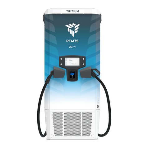
Tritium RTM75 User manual

RTM - 75kW
Installation Manual
INNOVATING YOUR FUTURE


TRI153.INS.046.3 - 08 March 2021
RTM - 75kW User Unit Installation Manual
www.tritium.com.au
Veel®isaregisteredtrademarkofTritiumPtyLtd.©2021TritiumPtyLtd
Important safety instructions 1
Packaging, handling, & receipt 3
Baseplate dimensions 6
Site preparation - Underground wiring 7
Site preparation - Above ground wiring 9
Site preparation - Local earth 11
Installation requirements & equipment 12
Unpacking 13
Installation 15
Wiring in - Underground gland and conduit 19
Wiring in - Above ground with conduit 21
Wiring in - Above ground with cable glands 22
Wiring in - Alternative gland plate 23
Ethernet port 25
SIM card installation 26
Closing checklist 27
Auxiliary wiring - Shunt trip 35
Auxiliary wiring - Emergency stop 36
Auxiliary wiring - GMI 37
Appendix 38
Contents

1TRI153.INS.046.3 - 08 March 2021
RTM - 75kW User Unit Installation Manual
www.tritium.com.au
Veel®isaregisteredtrademarkofTritiumPtyLtd.©2021TritiumPtyLtd
Important safety instructions
This manual contains important
instructions for the RTM-75kW DC
electric vehicle fast charger user unit.
Read the installation and operating
instructions before installing and
commissioning the equipment.
These instructions must be followed
during installation, operation, and
maintenance of the unit.
CAUTION
The RTM-75kW user unit must be
electrical personnel.
Grounding instructions
This unit must be connected to a
grounded, metal, permanent wiring
system. An equipment-grounding
conductor must be run with circuit
conductors and connected to the
equipment-grounding terminal or lead on
the electric vehicle charger.
Connections to the RTM-75kW user unit
must comply with all local codes and
ordinances.
Observe all pertinent national,
regional, and local safety laws and
regulations when installing and
commissioning the RTM-75kW user unit.
Identifying symbols
CRITICAL
CAUTION
RISK OF ELECTRIC SHOCK
Equipment Grounding
Conductor Symbol
ø Phase Symbol
Alternating Current Supply
Symbol
Wiring
Tritium recommends the use of copper
cables.
Take care to observe local regulations
same conduit, including the ethernet
link if used. In general, all conductors
occupying the same conduit must have
an insulation rating equal to at least the
maximum circuit voltage applied to any
conductor within the conduit.
SAVE THESE INSTRUCTIONS

2TRI153.INS.046.3 - 08 March 2021
RTM - 75kW User Unit Installation Manual
www.tritium.com.au
Veel®isaregisteredtrademarkofTritiumPtyLtd.©2021TritiumPtyLtd
Warning
commercial garage (repair facility) or
closer than 20 feet (6096 mm) of an
outdoor motor fuel dispensing device.
Input
3 phase AC, no neutral
Nominal current at nominal voltage
level
Maximum current at low line lev-
el (Nominal voltage - 10% and
PF>0.99)
Recommended over-current protec-
tion device required (OCPD) in site
distribution board
Worldwide: 125A breaker, US: 125A
breaker
The RTM-75kW user unit must be
connected to a circuit provided with
appropriate over-current protection in
accordance with the national, regional
and local regulations in the country of
installation.
Tightening torque
Wiring and earth terminals
20Nm
Weather rating
IP65 Electronics Enclosure
Usage limitations
Cord extension sets or second cable
assemblies must not be used in
addition to the cable assembly for
the connection of the vehicle to the
charger.
Adaptors must not be used to
connect a vehicle connector to a
vehicle inlet.
Important safety instructions
SAVE THESE INSTRUCTIONS

3TRI153.INS.046.3 - 08 March 2021
RTM - 75kW User Unit Installation Manual
www.tritium.com.au
Veel®isaregisteredtrademarkofTritiumPtyLtd.©2021TritiumPtyLtd
Read these instructions carefully to
become familiar with the RTM-75kW user
unit packaging and handling procedures
prior to unpacking and installation.
In all cases, the RTM-75kW user unit
must be transported to the installation
site in its original packaging and only
unpacked at the installation site.
Installation, commissioning, and servicing
of the RTM-75kW user unit should only be
Materials
The RTM-75kW user unit is
transported in a reinforced cardboard
crate.
Please respect the environment and
Storage
Store in the original packaging, in a
Store in a dry location, protected from
the weather (warehouse conditions).
Storage temperature:
Handling
Only lift the RTM-75kW user unit pack-
forklift, pallet jack, or with lifting straps
and forklift or crane. Check the weight on
the delivery documents, and ensure the
lifting apparatus used is compatible.
Receipt
Check that the crate packaging is in
good condition and that the RTM-75kW
user unit is not damaged.
If any problems are noted, make a formal
complaint to the carrier and notify your
supplier.
Packed crate weight
Up to 360kg
Crate size (in mm)
1190 (W) x 2135 (L) x 685 (H)
RTM-75kW weight
300kg
Packaging, handling, & receipt

TRI153.INS.046.3 - 08 March 2021
RTM - 75kW User Unit Installation Manual
www.tritium.com.au
Veel®isaregisteredtrademarkofTritiumPtyLtd.©2021TritiumPtyLtd
Site survey
installation site to determine the
and weight of the RTM-75kW user unit, in
accordance with local regulations.
The RTM-75kW user unit is best
installed following the recommended site
Ground xing
the ground through the baseplate
Fasteners are not supplied, because the
type required depends on the foundation
used and must be chosen by the installer
accordingly.
user unit securely to the foundation
through the baseplate in accordance with
Base plate dimensions.
Note: Keep the plastic inserts from the
bolts for use in the baseplate holes.
Conduit requirement
Up to Ø 110mm OD conduit maximum.
Ø50 and Ø25mm conduit standard.
Foundation requirements
have the appropriate density for the
weight of the user unit.
foundation and level of the RTM-75kW
Communications
capability.
Power supply
The RTM-75kW user unit is designed to
accommodate input wiring from either an
underground foundation or above ground.
High power (HP) input wiring
High power input wiring can be provided
scenarios:
1. A single multi-conductor cable
Ø27-38mm to suit the supplied M50
cable gland.
2. Running the wiring in a 50mm conduit
and installing using the provided M50
conduit adaptor and seal.
3. Individual wires can be used with the
M32 cable glands. Each individual cable
must be Ø13-18mm.
Auxiliary eld wiring
use the supplied M25 cable gland.
If the auxiliary wire is smaller than Ø10
the 25mm conduit installation must be
used.
CRITICAL
It is critical to product safety and
warranty that IP65 is achieved for
all input wiring.

5TRI153.INS.046.3 - 08 March 2021
RTM - 75kW User Unit Installation Manual
www.tritium.com.au
Veel®isaregisteredtrademarkofTritiumPtyLtd.©2021TritiumPtyLtd
Servicing distance
CAUTION
Additional space is required around the
RTM-75kW user unit for servicing, as
shown in the following image.
Measurements are from the RTM
foundation points.
Do not scale drawing.
Dimensions in mm.
800
MIN
330
Front of charger
300
Keep clear area
MIN
800
MIN
800
up to 4650mm
With cable
management
Cable range
Note: The grey areas shown in the image
must be kept clear of all obstructions.
This allows the user unit to be serviced
and provides clearance when the front
door of the User Unit is opened.

6TRI153.INS.046.3 - 08 March 2021
RTM - 75kW User Unit Installation Manual
www.tritium.com.au
Veel®isaregisteredtrademarkofTritiumPtyLtd.©2021TritiumPtyLtd
Baseplate dimensions
CAUTION
Notes:
•
• If installing on an existing foundation with above ground power, check
•
Do not scale. All dimensions shown in mm. A mounting stencil may be
supplied by Tritium at customer request.

7TRI153.INS.046.3 - 08 March 2021
RTM - 75kW User Unit Installation Manual
www.tritium.com.au
Veel®isaregisteredtrademarkofTritiumPtyLtd.©2021TritiumPtyLtd
Power supply preparation
When preparing the foundation, allow
approximately 1 metre of conduit and
wiring from the foundation surface.
1 metre
Large conduit installation
If the conduit used is greater than
Ø50mm, cut the conduit 20mm from the
foundation surface. Cut the wiring as
shown below.
Cut conduit 20mm
from foundation
HP Input
Ground
Ethernet
705mm
AUX
Field
Wiring
970mm
Note:
water and debris.
50 & 25mm conduit installation
390mm from the foundation surface. Cut
the wiring as shown below.
Note: This installation is not suited to
route ethernet wiring.
Cut conduit
390mm from
foundation
HP Input
Grounding
705mm
Field
Wiring
970mm
Cable gland installation
If the installation is using a 50mm
cable gland, cut the conduit 200mm from
the foundation surface. Cut the wiring as
shown below.
HP Input
Ground
Ethernet
705mm
Cut conduit
200mm from
foundation
AUX
Field
Wiring
970mm
Note:
water and debris.
Site preparation - Underground wiring

8TRI153.INS.046.3 - 08 March 2021
RTM - 75kW User Unit Installation Manual
www.tritium.com.au
Veel®isaregisteredtrademarkofTritiumPtyLtd.©2021TritiumPtyLtd
Prior to installation of the RTM-75kW, cut
the wiring as per this diagram and crimp
on lugs and bootlace ferrules.
Note: Drawing is not to scale.
Measure and cut on site.
Site preparation - Underground wiring
Cut wiring sheath
400mm from
foundation
Cut auxiliary
field wires
470mm from
sheath cut
Trim back auxiliary
field wires to suit
bootlace ferrules
(not supplied)
HP INPUT & GROUND WIRING
AUX FIELD
WIRING
L2
L3
L1
Lor
Cut L3 &
grounding
wire 205mm
from sheath
cut
Cut Input
wiring L1 & L2
185mm from
sheath cut
Trim back all
HP input wires and
grounding wires
to suit M8 lugs (EU)
OR M10 lugs (US)
and crimp on lugs
(not supplied)
ETHERNET
Trim to suit

9TRI153.INS.046.3 - 08 March 2021
RTM - 75kW User Unit Installation Manual
www.tritium.com.au
Veel®isaregisteredtrademarkofTritiumPtyLtd.©2021TritiumPtyLtd
Power supply preparation
power above ground.
Leave a minimum of 1500mm of conduit
and wiring from the right rear foundation
hole. Prior to installation, the conduit and
wiring will require trimming.
Minimum 1500mm
Charger front
Full conduit installation
rear foundation hole. Cut the wiring as
shown below.
Note: This installation is not suited to
route ethernet wiring.
Cut conduit
470mm from
foundation hole
AUX Field
wiring
1050mm
HP Input
Grounding
785mm
Charger front
Cable gland installation
Cut the conduit 100mm from the right
rear foundation hole. Cut the wiring as
shown below.
Cut conduit
100mm from
foundation hole
AUX
Field
wiring
1050mm
HP Input
Grounding
Ethernet
785mm
Charger front
Note:
debris.
Site preparation - Above ground wiring

10 TRI153.INS.046.3 - 08 March 2021
RTM - 75kW User Unit Installation Manual
www.tritium.com.au
Veel®isaregisteredtrademarkofTritiumPtyLtd.©2021TritiumPtyLtd
Site preparation - Above ground wiring
Prior to installation of the RTM-75kW, cut
the wiring as per this diagram and crimp
on lugs and bootlace ferrules.
Note: Drawing is not to scale.
Measure and cut on site.
Cut wiring sheath
480mm from
foundation hole
L2
L3
L1
HP INPUT WIRING & GROUND WIRING AUX FIELD
WIRING
Cut L3 &
grounding
wire 205mm
from sheath
cut
Cut auxiliary
field wires
470mm from
sheath cut
Cut Input
wiring L1 & L2
185mm from
sheath cut
Trim back all
HP input wires and
grounding wires
to suit M8 lugs (EU)
OR M10 lugs (US)
and crimp on lugs
(not supplied)
Trim back auxiliary
field wires to suit
bootlace ferrules
(not supplied)
ETHERNET
Trim to suit

11 TRI153.INS.046.3 - 08 March 2021
RTM - 75kW User Unit Installation Manual
www.tritium.com.au
Veel®isaregisteredtrademarkofTritiumPtyLtd.©2021TritiumPtyLtd
Site preparation - Local earth
Secondary point for connecting local
earth to the chassis.
the stud on the chassis. Follow local
regulation regarding lightning protection
and local earth bonding.
Note: This does not remove the need to
attach the Protective Earth conductor at
the charger input terminals.

12 TRI153.INS.046.3 - 08 March 2021
RTM - 75kW User Unit Installation Manual
www.tritium.com.au
Veel®isaregisteredtrademarkofTritiumPtyLtd.©2021TritiumPtyLtd
Installation requirements & equipment
These instructions provide a systematic
guide for installing and commissioning
the RTM-75kW user unit.
The RTM-75kW user unit must be
electrical personnel.
Observe all pertinent national, regional,
and local safety regulations when you
install and commission the RTM-75kW
user unit.
The RTM-75kW user unit has an IP65
electronics enclosure rating. However,
because it must be opened for installa-
tion, this is best done in dry weather or
under cover to avoid moisture or debris
ingress.
The RTM-75kW user unit must be
properly installed, assembled, and
commissioned according to these
instructions before it is used. Prior to
installation, contact your supplier to orga-
nise commissioning information.
Supplied with RTM-75kW user
unit:
• 5mm pin hex tool
•
•
•
cable glands
• External Ethernet connector
• Ferrite
• Conduit clamp
• 2x M5x12mm Screws
•
• Warranty documentation
• Baseplate template
Required equipment
(not supplied):
• Lifting apparatus. See page 3 for
weights. Ensure lifting apparatus is
• 110mm OD Conduit
•
• 1x M8 lug and 3x M10 lugs and
crimping tool (USA)
• Bootlace Ferrules 20AWG 0.5mm².
requirements. Refer to the Auxiliary
•
are not supplied, because the type
required depends on the foundation
used and must be chosen by the
installer accordingly.
• Socket set & ratchet
• Torque wrench
CAUTION
Do not work under suspended loads.
Two people may be required, because
the unit could swing.

13 TRI153.INS.046.3 - 08 March 2021
RTM - 75kW User Unit Installation Manual
www.tritium.com.au
Veel®isaregisteredtrademarkofTritiumPtyLtd.©2021TritiumPtyLtd
DOCUMENT KEY:
Items shown in orange are parts that
require action for that step.
1. Open crate
Move the crate as close to the prepared
installation site as possible. Ensure there
is enough room to manoeuvre the lifting
apparatus.
Remove the cardboard crate lid and slide
out the crate end.
2. Lift the RTM-75kW user unit to
vertical
Securely attach the lifting straps at the
top of RTM-75kW to the lifting apparatus
and gently raise to a standing position on
the shipping baseplate.
Note: The RTM-75kW user unit is
2030mm tall on the shipping baseplate.
When the user unit is upright, remove all
wrapping. Ensure the connection to the
lifting apparatus is secure at all times.
Shipping
Baseplate
Lifting Straps
Unpacking

TRI153.INS.046.3 - 08 March 2021
RTM - 75kW User Unit Installation Manual
www.tritium.com.au
Veel®isaregisteredtrademarkofTritiumPtyLtd.©2021TritiumPtyLtd
Important: To protect the cable plugs
from damage during installation, ensure
the cable plugs are not sitting in the
holsters.
holsters.
Take care while installing to ensure the
charging cables are not damaged by
placing them out of the way.
Unpacking

15 TRI153.INS.046.3 - 08 March 2021
RTM - 75kW User Unit Installation Manual
www.tritium.com.au
Veel®isaregisteredtrademarkofTritiumPtyLtd.©2021TritiumPtyLtd
3. Secure to foundation
Review section: Site preparation to
ensure the correct wiring and conduit
preparation.
Lift the RTM-75kW user unit and place
over the prepared foundation.
If wiring is provided from underground,
feed it through the power-in hole and
secure the RTM-75kW user unit to the
supplied.)
If the power is provided above ground,
secure the RTM-75kW user unit to the
foundation and proceed with the
installtion instructions.
Note: Use the plastic inserts in the holes
of the baseplate.
Important: Before proceeding to the
next step, check the cable plugs have
been removed from the holsters. Opening
the unit with the cable plugs sitting in the
holsters will damage the plugs.
1. Remove radiator panels
Fixing points for the front and rear
holes as shown.
Use the 5mm pin hex tool to unscrew the
the radiator panels. Pull the radiator
panels forward to reove, and safely store.
2. Remove shipping bolts
baseplate, located at the front and rear of
the radiator.
Installation

16 TRI153.INS.046.3 - 08 March 2021
RTM - 75kW User Unit Installation Manual
www.tritium.com.au
Veel®isaregisteredtrademarkofTritiumPtyLtd.©2021TritiumPtyLtd
5. Open hinged side panels
Open both side panels if the RTM-75kW
has cable management. Open only the
left hand side if there is no cable
managment.
Unhook the cable cord from the cut-out in
the top of the side panel when opening.
Unhook cable
If the RTM-75kW has cable management,
apply the instruction to both side panels.
If there is no cable management, open
the left hand side panel only.
Use the 5mm pin hex tool to unscrew the
2x security screws on each side panel.
Remove the security screws and washers.
Open the side panels.
Installation

17 TRI153.INS.046.3 - 08 March 2021
RTM - 75kW User Unit Installation Manual
www.tritium.com.au
Veel®isaregisteredtrademarkofTritiumPtyLtd.©2021TritiumPtyLtd
FLIP THE LATCH
HANDLE UP
TURN THE LATCH
HANDLE ANTI
CLOCKWISE
TO SLIDE THE
LATCH AWAY
FROM THE HOOK
PULL THE LATCH
HANDLE AWAY
FROM THE LATCH
TO DISENGAGE
FROM THE HOOK
OPENING THE LATCHES
LATCH HOOK
COMPRESSING THE DOOR SEAL
ASSISTS IN DISENGAGING
THE LATCH FROM THE HOOK
1
2 3
7. Remove escutcheon
Remove the 6x M8 hex bolts and
escutcheon.
6. Open door
the door to the enclosure.
Starting with the two latches in the
centre, follow the instructions shown for
opening the latches. Once all latches are
disengaged, open the hinged door.
Installation
Other manuals for RTM75
1
Table of contents
Other Tritium Automobile Accessories manuals
