Strong International XENON FXPS User manual
STRONG INTERNATIONAL
a division of Ballantyne of Omaha, Inc.
4350 McKinley Street
Omaha, Nebraska 68112 USA
Tel 402/453-4444 • Fax 402/453-7238
XENON POWER SUPPLY
High ReactanceType FXPS
Rev. 10/98

CONTENTS
Page
PREFACE .............................................. 1
INSTALLATION ................................... 1
Tap Adjustment ................................ 2
MAINTENANCE .................................. 3
ILLUSTRATIONS
FXPS Standard ................................ 4
Model LB ..................................... 5
INSTALLATION DIAGRAM ............... 6
TROUBLESHOOTING ........................ 7
WIRING DIAGRAMS
FXPS Standard ................................ 10
Model LB ..................................... 11
PARTS LIST .......................................... 12
SPECIFICATIONS ................................ 15

PREFACE
THE FXPS XENON POWER SUPPLY manufactured by Strong International is a
high reactance unit utilizing silicon diodes as the power conversion elements. All models are designed
for 50/60 Hertz operation, and are available in varying AC input types, depending upon the configu-
ration of the main power transformer. Check the Equipment Data Plate to determine the exact AC
requirement prior to installation.
COARSE AND FINE TAPS are easily set to regulate the DC current to the xenon
bulb. Some models of FXPS power supplies have the capability of overdriving a xenon bulb;
carefully check the power requirements specified by the bulb manufacturer and do not exceed the
maximum current stated.
DC OUTPUT to the xenon bulb is filtered by means of a choke and filter capacitors.
A relay-operated resistor circuit reduces the inrush current upon ignition to prolong bulb life.
Suppression capacitors prevent RF interference in the theatre sound system.
OVERSIZE HEAT SINKS disperse the heat normally generated by the silicon diodes.
High-wattage power supplies include an internally wired blower for additional heat dissipation. Ther-
mal switches act as safety interlocks to shut down the power supply and protect the rectifier diodes
in the event temperatures reach excessive levels.
A STEPDOWN TRANSFORMER reduces the input line to supply 115 V.AC to power
lamphouse control circuits as required. The transformer is protected by a three ampere in-line fuse.
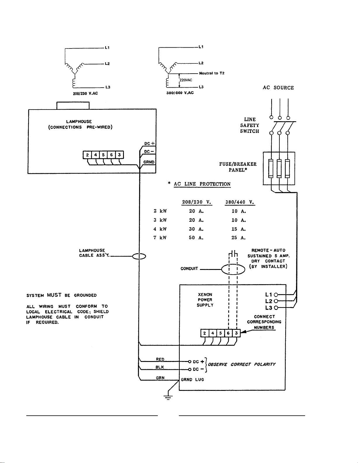
INSTALLATION
CHECK THE EQUIPMENT DATA PLATE and make certain that the AC source
conforms to the power requirements of the main transformer. The location of the AC input terminals
is shown on Pages 4 and 5. See the Installation Diagram on Page 6 for detailed AC hook-up, line
protection, and lamp connections. The AC service wiring should be installed by a licensed electri-
cian in conformance to local codes. The unit must be connected to an adequate earth ground.
THE AC LINE to the xenon power supply must include a marked line safety switch
or other power disconnect device adjacent to the unit and accessible to the operator. For operator
safety, it is necessary to turn off all power to the unit when adjusting or servicing the xenon power
supply. This safety switch or power disconnect should be tagged OFF - UNIT UNDER REPAIR
when the power supply is being serviced.
1
INSTALLATION (continued)
OBSERVING ALL SAFETY PROCEDURES, install a xenon bulb of the desired
wattage into the lamphouse. Check the bulb manufacturers documentation to determine the recom-
mended current range of the bulb. A new bulb is normally first operated at nominal current, which
is around 85% of the maximum level. DO NOT, at any time, exceed the maximum current level
specified by the bulb manufacturer.
IGNITE THE XENON BULB and check the current as indicated on the lamphouse
ammeter. Allow (30) seconds for the current to stabilize and provide an accurate reading. If the
current is not within the desired range, extinguish the bulb. It will be necessary to increase or de-
crease the DC output.
WARNING
Turn off ALL primary AC power before making any
adjustments or performing service procedures. Allow
several minutes for the capacitors to drain stored en-
ergy. The power supply normally operates warm to hot;
allow the unit to cool to room temperature.
OUTPUT CURRENT ADJUSTMENT
Fine adjustment of the DC current is made to the NUMBERED taps found on the upper three
terminal blocks (TB4, TB5, TB6). Fine taps are numbered 1-2-3-4, with 1 providing the lowest
output, increasing to 4, yielding the highest output. A fine tap adjustment raises or lowers the
current approximately four amperes. The three fine tap terminal blocks are interconnected by means
of a three-lead jumper wire assembly attached to like-numbered terminals.
Toincrease the DC output, move the jumper wire assembly to tap the next (3) higher numbered
terminals, for example, move from terminals 2 to terminals 3. ALL TAPS MUST BE ON THE
SAME NUMBERED POSITION (1-1-1, 2-2-2, 3-3-3, or 4-4-4). If the DC output is still too low
when terminals 4 are interconnected, see the following instructions for adjusting coarse taps.
Todecrease the DC output, move the jumper wire assembly to tap the next (3) lower numbered
terminals, for example, move from terminals 3 to terminals 2. ALL TAPS MUST BE ON THE
SAME NUMBERED POSITION (1-1-1, 2-2-2, 3-3-3, or 4-4-4). If the DC output is still too high
when terminals 1 are interconnected, see the following instructions for adjusting coarse taps.
Coarse adjustment of the DC current is made to the LETTERED taps found on the lower three
terminal blocks (TB1, TB2, TB3). Coarse taps are lettered W-X-Y-Z, with W providing the lowest
output, increasing to Z at the highest output. The coarse tap terminals connect to contactor termi-
nals T1, T2, and T3. The (3) contactor leads must connect to the same lettered step (W-W-W, etc.).
A coarse tap adjustment raises or lowers the current approximately twelve amperes.
2

INSTALLATION (continued)
Toincrease the coarse DC output, move each of the contactor leads to tap the next higher lettered
terminals, for example, move from terminals W to terminals X. ALL TAPS MUST BE ON
THE SAME LETTERED POSITION (W-W-W, X-X-X, Y-Y-Y, or Z-Z-Z). Place the fine tap
jumper on 1-1-1. Ignite the lamp, check the output, and increase the fine tap setting as required.
Todecrease the coarse DC output, move each of the contactor leads to tap the next lower lettered
terminals, for example, move from terminals Y to terminals X. ALL TAPS MUST BE ON
THE SAME LETTERED POSITION (W-W-W, X-X-X, Y-Y-Y, or Z-Z-Z). Place the fine tap
jumper on 1-1-1. Ignite the lamp, check the output, and increase the fine tap setting as required.
INSPECT TAP CONNECTIONS to verify that the terminal is clamping the copper
conductor, not the insulation. Make certain all terminal clamping screws are tight.
WHENEVER MAKING A COARSE ADJUSTMENT, again check the lamphouse
ammeter and make certain the current is within the desired range. A fine tap re-adjustment is fre-
quently required after changing coarse taps.
AFTER PROLONGED OPERATION, the light output of the xenon bulb will decrease.
This is a normal factor of bulb aging, and can be compensated by raising the DC output of the xenon
power supply. If the bulb was first operated at nominal current, the power supply output can
gradually be increased to, but not in excess of, he maximum current specified by the bulb manufac-
turer. Increase the current as instructed above. Decrease the power supply output to its former
nominal current level upon the installation of a new replacement bulb.
MAINTENANCE
VERY LITTLE MAINTENANCE is required to keep this power supply in good
operating condition. Like most booth equipment, regularly scheduled cleaning is most important.
WARNING
Turn off ALL primary AC power before making any adjustments or
performing service procedures. Allow several minutes for the
capacitors to drain stored energy. Allow the power supply to cool
to room temperature.
1. Remove all accumulated dust and dirt from the rectifier. Vacuum the heat sinks. Make certain all
air inlets and outlets are unobstructed.
2. Regularly check all electrical connections for tightness. Clean, retighten, or replace any discolored
connections or terminals.
3. Every three months, apply a drop or two of SAE 20-weight oil to the squirrelcage blower motor
bearings (on units so equipped). Muffin fans require no lubrication.
3

C1A
C1B TB4
TB5 TB6
T2
L1
TB3
TB2
TB1
DATA
PLATE
T2
F1
L1
R3
K1 AC
INPUT
C2A
C2B
B1
CR4
CR5
CR6
CR1
CR2
CR3
R2
K2
C1A
C1B
CR1,2,3: Forward Diodes
CR4,5,6: Reverse Diodes
TB1,2,3: Fine Taps
TB3,4,5: Coarse Taps
Xenon Power Supply Type FXPS
Strong Lamphouse Leads:
DC+ to CR1,2,3 Heat Sink
DC- to L1 Buss Bar
2 & 4 to T2 Output (115 V.AC)
5 & 6 to K1 Coil (115 V.AC)
7 & 8 to 220 V.AC 1 ph.
T1
S1
4
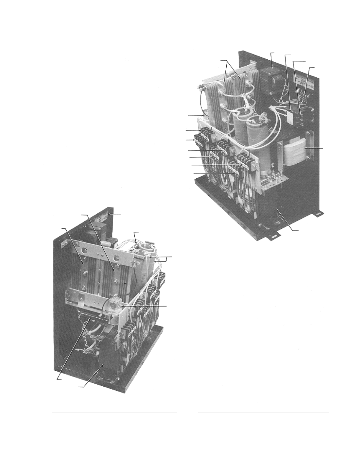
T2 K1 AC
INPUT
TB7
L1
T1
DIODE HEAT SINKS
(S1 not shown)
K2
TB4
TB1
TB5
TB2
TB6
TB3
DATA PLATE
R2
CR1
CR2
CR3
CR4
CR5
CR6
C1
C2
K2
R1
T1
FXPS Power Supply
Model “LB”
Strong Lamphouse Leads:
DC+ to CR1,2,3 Heat Sink
DC- to L1 Buss Bar
2 & 4 to T2 Output (115 V.AC)
5 & 6 to K1 Coil (115 V.AC)
TB1,2,3: Fine Taps
TB3,4,5: Coarse Taps
CR1,2,3: Forward Diodes
CR4,5,6: Reverse Diodes
5
Strong Lamphouse Leads:
DC+ to CR1,2,3 Heat Sink
DC- to L1 Buss Bar
2 & 4 to T2 Output (115 V.AC)
5 & 6 to K1 Coil (115 V.AC)
7 & 8 (Ultra 80 only) to 220 V.AC 1 ph.
INSTALLATION WIRING DIAGRAM
6

TROUBLESHOOTING
POWER LINE PROBLEMS
PRIMARY POWER (AC source) problems are most commonly (a) complete loss of AC power,
or (b) phase loss, in which one phase loses power.
a) Check line safety switch (ON). Check fuses or breakers in supply line. Using an AC
voltmeter, measure input power at contactor terminals L1, L2, L3.
b) When power is lost on one phase, the current ripple will increase and trip the AC line circuit
breaker (at the wall, or in a Console Distribution Panel). To detect a lost phase, measure the AC
voltage phase-to-phase at contactor input terminals L1, L2, and L3.
PROBLEMS of this nature, once detected, are generally corrected by the power supplier
(i.e. the local utility company).
BOOST CIRCUIT PROBLEMS
THE BOOST CIRCUIT generates the high open circuit (no load) DC voltage which, in
conjunction with the igniter pulse, will ignite the xenon bulb. The open circuit voltage should
measure at least 110 V.DC. It is displayed briefly on the lamphouse ammeter by pressing the VOLT-
AGE button at ignition, or the reading can be sustained by disabling lamphouse ignition by removing
one AC lead from the igniter feed (Strong lamphouse: 5 or 6).
A TERTIARY WINDING on the main transformer (T1) supplies the source for the Boost
Circuit. Three wires derive from the T1 transformer; two are single conductors, and the third is a
soldered pair. The Boost Circuit should be connected only to the (2) single conductors. Filter
capacitors C1 & C2 store energy and also contribute to bulb ignition.
CONTROL CIRCUITRY
THE MAIN POWER TRANSFORMER is energized by contactor K1, which is pulled by (a)
an automation system closure or (b) manual actuation of the lamphouse ON switch. All lamphouse
interlock switches (Door, Air, etc.) must also be closed to complete the contactor circuit.
ANY INTERRUPTION of the control circuit will disable K1 and open the AC circuit to the
rectifier. In addition to the above lamphouse interlock switches, thermal switch S1, mounted to the
rectifier heat sink, will open and disable K1 if the temperature at the heat sinks exceeds 190° F. (88°
C.). The S1 switch will automatically re-set when temperatures fall to safe levels.
STEPDOWN TRANSFORMER T2 is protected by a (3) Ampere in-line fuse F1. In the
event of a failure of a lamphouse control component (blower, igniter, etc.), the fuse will open. This,
in turn, will disable the lamphouse control circuit and cause the power supply contactor K1 to open.
Repair or replace the faulty lamphouse component before replacing the fuse (3 A. Std.); do not
overfuse.
WARNING: Exercise extreme caution when taking
voltage measurements in a power ON condition.
Allow the capacitors (2) minutes to discharge.
7

TROUBLESHOOTING (continued)
POWER CONVERSION PROBLEMS
RECTIFICATION (AC to DC) is performed by bridge diodes CR1 - CR6. CR1, CR2, and
CR3 are forward diodes, and CR4, CR5, and CR6 are reverse diodes. The two types are not
interchangeable.
AN OPEN DIODE will cause a pronounced flicker in the light output. Two or more open
diodes will disable bulb ignition. A shorted diode will trip the circuit breaker (at the wall or in a
Console Distribution Panel) protecting the AC input line. See the following DIODE TESTING &
REPLACEMENT section.
BANKED CAN CAPACITORS C1 & C2, and Choke L1, filter the rectified DC output. C1
and C2 capacitors also store energy to contribute to the open circuit ignition discharge. A shorted
capacitor can trip the AC circuit breaker. A faulty choke can allow excessive ripple, which can open
the AC circuit breaker.
RELAY K2, in the presence of high DC open circuit voltage, will pull and place Resistor R2
in series with Capacitors C1 and C2. This resistor limits the inrush surge and prolongs the discharge
of C1 & C2 to promote bulb ignition. If K2 relay fails, ignition may become erratic, and R2 may
remain in circuit. With R2 in circuit, ripple will increase to a level noticeable in light output, but not
necessarily enough to trip the AC line circuit breaker.
DIODE TESTING & REPLACEMENT
1. Disconnect the diode from its circuit. Inspect for discoloration, oxidation, or loose crimp at lead
junction.
2. A shorted diode will show low resistance in both directions. An open diode will have infinite
resistance in both directions. An Ohmmeter test is required.
3. a) Analog VOM: Select R x 1 Ohm scale. With meter leads connected in one direction, the
reading should be zero (or nearly so); reversing the meter leads should show very high resis-
tance. If the diode does not exhibit these characteristics, replace it. NOTE DIODE TYPE:
forward or reverse.
b) Digital VOM: Select Diode Test. With meter leads connected in one direction, the reading
should be OL (overload); reversing the meter leads should display approximately .4 volt. If the
diode does not exhibit these characteristics, replace it. NOTE DIODE TYPE: forward or reverse.
4. Carefully clean the area of the heat sink in which the diode mounts. Apply heat sink compound
(Radio Shack #276-1373 or equivalent) using a wood or plastic spatula or stick. A thin layer is
adequate.
WARNING: HEAT SINK COMPOUND IS HIGHLY CAUSTIC. Do not apply with fingers; keep
away from eyes. Carefully follow ALL the instructions printed on the package.
5. Install the new diode and tighten securely for maximum mechanical contact and electrical conduc-
tion. Clean and firmly secure the lead terminal to the buss.
8

TROUBLESHOOTING (continued)
Contactor does not energize (no audible click)
1. Line safety switch open. Turn ON.
2. Console Rectifier circuit breaker off. Turn ON.
3. Circuit breaker or fuse in AC line open. Check AC source.
4. Lamphouse interlock switch open. See lamphouse manual.
5. Faulty contactor coil or loose connection at coil terminals. Repair or replace.
Contactor pulls but lamphouse igniter does not fire
1. Faulty contactor contacts. With coil energized, check for continuity across the contacts from the
L side to the T side; repair or replace if defective.
2. Insufficient DC output. See INSTALLATION section; increase tap setting as required.
3. Faulty igniter. See lamphouse manual.
4. Low open circuit voltage (less than 110 V.DC).
a) Check ceramic resistor R1; should be in circuit and measure 100 Ohms.
b) Check boost diodes CR7 and CR8. See preceding DIODE TESTING section.
c) Check filter capacitors C1 and C2. Replace if defective.
NOTE: Lamphouse Emergency Ignite switch (if present) will frequently overcome low open
circuit voltage condition, but will not permit normal autostrike function.
Bulb requires multiple ignition pulses to light
1. Insufficient DC output. See INSTALLATION section; set tap setting as required.
2. Faulty K2 relay. Replace if defective.
3. Faulty or expired xenon bulb. Check for darkened envelope, worn electrodes; replace if required.
4. One or more faulty bridge diodes. See preceding DIODE TESTING section.
Bulb goes out during operation
1. Excessive heat at rectifier heat sinks; thermal switch S1 opening. Check for free air flow, blower(s)
operating at full speed. Check for loose connection.
2. Faulty lamphouse interlock switch (Door, Air, etc.). See lamphouse manual.
Excessive flicker in light output
1. Improper tap setting. All taps must be on same numbered or lettered step.
2. Faulty bridge diode. See preceding DIODE TESTING section.
3. Faulty xenon bulb. Check for cracked or sagging electrode(s).
4. Open filter capacitor C1 or C2. Replace if defective.
Bridge diodes (CR1-6) fail repeatedly
1. Insufficient air flow; defective blower. Clean, repair, or replace as required.
2. Incorrect replacement diode. Use only the specified rated diode(s).
9

FXPS Standard Model Wiring Diagram
See Page 4
10

FXPS Model “LB” Wiring Diagram
See Page 5
11

PARTS LIST
XENON POWER SUPPLY Type FXPS
2000 - 7000 Watt
Ref.
Desig. Part No. Description
B1 91-98027 Blower, 115 V.AC, Muffin Type (as shown)
B1 81-98057 Blower, 115 V.AC, Squirrelcage (not shown)
C1,2 81-08007 Filter Capacitor, 10,000 µf, 250 V.
- 61-06001 Capacitor Clamp (2 reqd.)
- 82-40256 Capacitor Mounting Plate (Model LB)
C1A,B 61-08027 Filter Capacitor, 5400 µf, 200 V.
- 61-06001 Capacitor Clamp (2 reqd.)
- 82-40264 Capacitor Mounting Plate
C2A,B 61-08027 Filter Capacitor, 5400 µf, 200 V.
- 61-06001 Capacitor Clamp (2 reqd.)
- 82-40248 Shorting Bar, A to B (2 reqd.)
C3 81-08029 Capacitor, .01 µf, 600 V.DC
C4 81-08005 Capacitor, .33 µf
- 92-70045 Capacitor Assembly (C3 & C4)
C5 81-08029 Capacitor, .01 µf, 600 V.DC
C6,7 81-08025 Ceramic Capacitor, .005 µf, 30 V.DC
- 82-70012 Voltage Doubler Assembly (C6,C7,CR7,CR8)
CR1,2,3 81-47004 Forward Diode, 100 A. 300 V. (1N3290)
CR4,5,6 81-47001 Reverse Diode, 100 A. 300 V. (1N3290R)
- 91-98031 Buss Bar, Diode Lead Connection (3 reqd.)
- 82-20032 Heat Sink (2 reqd.)
- 82-40254 Upper Heat Sink Brace, Phenolic
- 82-40255 Lower Heat Sink L Bracket, Phenolic
CR7,8 81-47006 Boost Diode, 3 A. 600 V.
- 82-70012 Voltage Doubler Assembly (C6,C7,CR7,CR8)
CR9 81-17002 Zener Diode, 5 W. 36 V. (1N5365B)
F1 2353-0300 Fuse, 3 A. 250 V. (3AG)
- 81-21006 Fuse Holder, In-Line (Model LB)
- 21-21039 Fuse Holder, Panel Mount
L1 ** Choke (Order by Equipment Type)
K1 81-14001 Contactor, 115 V.AC, 50/60 Hz. Coil
K2 2501-3150 Plug-In Relay, 48 V.DC Coil
- 82-70014 Relay Socket Assembly, with C5 Capacitor
- 81-56002 Spacer, Relay Socket (2 reqd.)
- 23862000 Relay Support Bracket (Model LB)
- 91-37002 Relay Hold-Down Spring
12

Ref.
Desig. Part No. Description
R1 81-46026 Ceramic Resistor, 100 Ohm, 100 W.
R2,3 92-70026 Nichrome Limiter Resistor
R4-7 81-46006 Bleeder Resistor, 2500 Ohm, 10 W.
S1 81-61010 Thermal Switch
- 82-70013 Thermal Switch (S1) & Leads, Wired Assembly
T1 ** Power Transformer (Order by Equipment Type)
T2 61984000 Stepdown Transformer
- 82-40353 Insulated Mounting Plate, T2 & F1
- 21-62059 Barrier Strip, (3) Terminal
TB1-6 81-62001 Tap Terminal Block (6 reqd.)
- 82-40047 Insulated Mounting Plate, TB1-6
TB7 21-62009 Control Circuit Barrier Strip, (5) Terminal
** Order Numbers: Choke & Power Transformer
Wattage, Input Voltage L1 Choke T1 Power Transformer
2000 Watt, 208/230 V. 91-64005 91-64008
2000 Watt, 380/440 V. 91-64005 91-64009
3000 Watt, 208/230 V. 91-64005 91-64004
3000 Watt, 380/440 V. 91-64005 91-64006
4000 Watt, 208/230 V. 1249314-3 91-64012
4000 Watt, 380/440 V. 1249314-3 91-64001
7000 Watt, 208/230 V. 91-64013 91-64011
7000 Watt, 380/440 V. 91-64013 91-64007
Replacement T1 Transformer includes (6) 81-62001 Tap Terminal Blocks (TB1-6) and
(1) 82-40047 Terminal Block Mounting Plate.
Replacement Bridge Rectifiers
92-70034 Diodes & Heat Sink Assembly, Complete (Standard model)
See Page 4, CR1-6
82-70011 Diodes & Heat Sink Assembly, Complete (Model LB)
See Page 5, CR1-6
FXPS Parts List (continued)
13

MECHANICAL & MISCELLANEOUS COMPONENTS
(Not Otherwise Listed)
Standard Model (See Page 4)
1249110-1 Base Chassis, Welded Assembly
82-40040 Support Bracket, Rectifier Heat Sinks (2 reqd.)
82-40267 Cabinet End Panel, Plain
82-40268 Cabinet End Panel, with Grille & Knock-Outs
82-40269 Cabinet Side Panel (2 reqd.)
82-40275 Cabinet Top Cover
Power Supply Cabinet (not shown) not supplied
with Console-Mounted (Optimax, Highlight) units.
Model LB (See Page 5)
23881000 Chassis Welded Assembly, L Bracket
62-40069 Support Bracket, Rectifier Heat Sinks
82-70010 Lead Assembly, L1 Choke to Negative Heat Sink
82-70015 Lead Assembly, Bridge Diodes to T1 Transformer (3 reqd.)
77839000 Negative Lead Assembly, 60" (to Console Lamphouse)
77840000 Positive Lead Assembly, 48" (to Console Lamphouse)
FXPS Parts List (continued)
14

EQUIPMENT SPECIFICATIONS
Xenon Power Supply
Type FXPS
MODEL WATTAGE; AC INPUT TYPE NO. DC AMPS DC VOLTS
FXPS 2kW 2000 Watt; 208/230 V. 93-90007 60-100 25
FXPS 2kW 2000 Watt; 380/440 V. 93-90010 60-100 25
LBPS 2kW 2000 Watt; 208/230 V. 77052-01 60-100 25
LBPS 2kW 2000 Watt; 380/440 V. 77052-01 60-100 25
FXPS 3kW 3000 Watt; 208/230 V. 93-90013 80-120 30
FXPS 3kW 3000 Watt; 380/440 V. 93-90016 80-120 30
LBPS 3kW 3000 Watt; 208/230 V. 77053-01 80-120 30
LBPS 3kW 3000 Watt; 380/440 V. 77053-02 80-120 30
FXPS 4kW 4000 Watt; 208/230 V. 93-90019 100-150 30
FXPS 4kW 4000 Watt; 380/440 V. 93-90022 100-150 30
LBPS 4kW 4000 Watt; 208/230 V. 77054-01 100-150 30
LBPS 4kW 4000 Watt; 380/440 V. 77054-02 100-150 30
FXPS 7kW 7000 Watt; 208/230 V. 93-90025 130-180 40
FXPS 7kW 7000 Watt; 380/440 V. 93-90028 130-150 40
LBPS 7kW 7000 Watt; 208/230 V. 77057-01 130-150 40
LBPS 7kW 7000 Watt; 380/440 V. 77057-02 130-150 40
NOTES:
1. FXPS = Standard Chassis; available with Cabinet; See Pages 4 & 10
2. LBPS = L Bracket Chassis (Model LB); See Pages 5 & 11
3. For 2500 Watt Operation, use 2 kW or 3 kW Supply
(Consult with Strong International Dealer per Application)
4. For 3600 Watt Operation, use 3 kW or 4 kW Supply
(Consult with Strong International Dealer per Application)
5. 7000 Watt Operation for 70mm and Special Venue ONLY
6. Average Shipping Weight: Approx. 250 lb. (113.5 kg)
15

Table of contents
Other Strong International Power Supply manuals


