Strong Rising SEW290 Manual

SEW290 WCDMA Module
Strong Rising SEW290 Module
Technical User Guide
Version:V1.0
Dec, 15th, 2012
Shenzhen Strong Rising Electronics Co.,Ltd
www.strongrising.com

1
Strong Rising SEW290 Module
Copyright Statement
Copyright © 2012 by Strong Rising.
www.strongrising.com
The copyright of this User Manual belongs to Strong Rising Elctronics and under the protection
of Copyright Law of the People’s Republic of China and other relative laws.
No part of this publication may be excerpted, reproduced, translated or utilized in any form or by
any means (electronic or mechanical, including photocopying and microfilm) without prior
written permission from Strong Rising Elctronics.
The information in the document is subject to change without notice. At the same time we reserve
the right to revise or recall the User Manual.
If there is anything unclear in this manual, please contact us or our agent or seller.

2
Strong Rising SEW290 Module
Technical Support
Shenzhen Strong Rising Electronics Co.,Ltd. was establised in January 2004.We mainly engage
in the research and development, production and sales of communications terminal products,is the
earliest into wireless data card in the field of one of the professional manufacturers.
We can provide WCDMA/EDGE/cdma2000 module customers technical support through
website,telephone,IM,E-Mail etc,and also onsite supports.
The Strong Rising website www.strongrising.com provides the relevant industry information and
module technical documentation.
You can also call us at hotline 400-0690-009 for more supports.
EU Regulatory Conformance
Hereby,Shenzhen Strong Rising Electronics Co., Ltd. Declares that this device is in compliance
with the essential requirements and other relevant provisions of Directive 1999/5/EC.
SEW290 WCDMA Module
3
Preface
Summary
This manual is applicable for SEW290 module. This manual takes SEW290 for example to
instruct the users how to design the hardware and how to quickly and conveniently design
different kinds of wireless terminals based on the modules.
Target Readers
System designing engineers
Mechanical engineers
Hardware engineers
Software engineers
Test engineers
Brief Introduction
The manual contains 5 chapters, shown as below:
Chapter Contents
DESCRIPTION Introduces SEW290 module’s technical specs and relevant documents and
abbreviations.
SEW290 MODULE
INTRODUCTION
Introduces SEW290 module’s principle diagram and relevant standards.
PIN DEFINITIONS Introduces SEW290 module’s PIN names and function.
DESCRIPTIONS OF
HARDWARE INTERFACES
Introduces SEW290 module’s hardware interfaces.
MECHANICAL DESIGN Introduces SEW290 module’s appearance, assembly diagram and antenna
connector’s mechanical specifications.
Update History
Document Reversion
V1.0 (2012-11-1)
The first version released。

SEW290 WCDMA Module
4
CONTENTS
CopyrightStatement.........................................................................................................................................1
TechnicalSupport..............................................................................................................................................2
Preface...............................................................................................................................................................3
Summary...................................................................................................................................................3
TargetReaders..........................................................................................................................................3
BriefIntroduction......................................................................................................................................3
UpdateHistory..........................................................................................................................................3
1Description.................................................................................................................................................6
1.1TechnicalSpecification...................................................................................................................6
1.1.1Descriptionsofspecs..........................................................................................................6
1.1.2BasicFunctions....................................................................................................................6
1.1.3ModuleInterfaces...............................................................................................................6
1.1.4TechnicalParameters..........................................................................................................7
1.2AmbientTemperatureParameters......................................................................................................8
1.2Abbreviations.................................................................................................................................8
2ModuleIntroduction..................................................................................................................................9
3PINDefinitions.........................................................................................................................................11
4DescriptionsofHardwareInterfaces.......................................................................................................13
4.1Description...................................................................................................................................13
4.2PowerandReset...........................................................................................................................13
4.2.1PowerDesign....................................................................................................................13
4.2.2Reset.................................................................................................................................14
4.3UART............................................................................................................................................15
4.44.4USIMCard..............................................................................................................................15
4.5Audio................................................................................................................................................17
4.5PCM..............................................................................................................................................18
4.6USB2.0.........................................................................................................................................19

SEW290 WCDMA Module
5
4.7AntennaInterface.........................................................................................................................20
4.7.1AntennaDesignRequirements.........................................................................................20
4.7.2Interference......................................................................................................................20
4.8LEDStatusIndicator.....................................................................................................................20
4.9SleepandWake_up......................................................................................................................21
4.9.1Sleep..................................................................................................................................21
4.9.2WAKEUP_OUT...................................................................................................................21
5MechanicalDesign...................................................................................................................................21
5.1Appearance..................................................................................................................................21
5.21.1ModuleMainboardPCBLayoutDiagram..................................................................................23
5.2AntennaConnectorMechanicalDimensions...............................................................................24
5.3Module’sFasteningMethod........................................................................................................24
6Importantannouncement……………………………………………………………………………………………………………….25
SEW290 WCDMA Module
6
1Description
This manual is applicable for SEW290 module. SEW290 module is WCDMA/HSDPA/HSUPA/GSM/GPRS
/EDGE manufactured by Strong Rising, which has the functions like voice, SMS and data service. The peak
value of forward data rate can reach up to 7.2Mbit/s and reverse data rate can reach up to 5.76Mbit/s. The data
service could provide users with economical high-speed Internet access and wireless data service. Using
SEW290 can easily help you realize the following: MODEM, U-Modem, Embedded Module, Wileless Phone,
Smart Phone, Multimedia Phone and Touch-screen Telecom Device, etc.This manual describes SEW290
module’s logic structure, hardware interface and main functions, and provides reference design for the hardware
and mechanics.
According to the designer, Shenzhen Strong Rising Electronics Co.,Ltd., we hereby declare that there’s no
difference between the model SPW270, SPW290, STW290, PCI270, PCI290, SEV550, SEV750, SEV850,
MU270, MU290, MC550, MC750, MC850, SEW270, SEW291, SEW702, STV680 and SEW290, they are
accordant in both hardware and software.
1.1 Technical Specification
1.1.1 Descriptions of specs.
Please refer to Table 1-1 for the specifications of SEW290.
Table 1-1 Module specification
Module Model技术体制工作频段
Technical System Work Frequency
SEW290 WCDMA/HSPA/GSM/GPRS/EDGE
GSM/GPRS/EDGE:
GSM850/EGSM900/DCS1800/PCS1900
WCDMA/HSDPA/HSUPA:2100M
Hz,/850MHz
1.1.2 Basic Functions
Please refer to Table 1-2 for the module’s basic functions.
Table 1-2 Module’s basic functions
Basic Functions Descriptions
Voice Two input/output differential and single end analog audio,support PCM
Data Service GSM、GPRS、EDGE、WCDMA(CS、PS UL384kbps)、HSUPA 7.2Mbps
SMS Support both TEXT and PDU.
1.1.3 Module Interfaces
Please refer to Table 1-3 for the module’s Interfaces
Table 1-3 Module’s Interfaces
Interface Descriptions
Power interface Used to supply the power, reset, and power on-off the module
Audio interface Two audio input/output, one for diffenrential, one for single-end
USIM interface Machine and card separation
USB interface USB2.0 High Speed
UART interface Support software customization
SEW290 WCDMA Module
7
Antenna interface Antenna interface,50 ohm input impedance. User can connect an antenna with
coxial cable to the antenna connector.Please notice the dimension of the coxial
cable should match the module’s connector.
1.1.4 Technical Parameters
Please refer to Table 1-4 for the module’s technical parameters.,
Table 1-4 Technical parameters
Technical parameters Descriptions
Input voltage 3.4V-4.2V
Maximum current 1800mA @ -102 dBm
Standby current(Avg.) 10mA @ -75 dBm
Talk current(Avg.) 230mA @ -75 dBm
Sleep current(Avg.) 3 mA
Rx. sensitivity GSM all bands:<-102dB,typical testing value:-108dBm
WCDMA all bands:<106.5dBm,typical testing value:-109dBm
Maximum Tx. power
GSM850&EGSM900 GMSK Mode:31.5±0.5dBm
8PSK Mode:27.5±0.5dBm
GSM1800&PCS1900 GMSK Mode:27.9±0.6dBm
8PSK Mode:24.5±0.5dBm
WCDMA
Band I(W2100) 22.5±0.5dBm
Band V(W850) 22.5±0.5dBm
Operating Band
GSM850 X:824~849 MHz
RX:869~894 MHz
EGSM900 TX:880~915 MHz
RX:925~960MHz
DCS1800 TX:1710~1785MHz
RX:1805~1880MHz
PCS1900 TX:1850~1910MHz
RX:1930~1990MHz
WCDMA 2100 TX:1920-1980MHz
RX:2110-2170MHz
WCDMA 850 TX:824-849MHz
RX:869-894MHz

SEW290 WCDMA Module
8
1.2Ambient Temperature Parameters
Please refer to Table 1-5 for the module’s ambient temperature parameters.
Table 1-4 Ambient temperature parameters
1.2 Abbreviations
ADC Analog-Digital Converter
AFC Automatic Frequency Control
AGC Automatic Gain Control
ARFCN Absolute Radio Frequency Channel Number
ARP Antenna Reference Point
ASIC Application Specific Integrated Circuit
BER Bit Error Rate
BTS Base Transceiver Station
CDMA Code Division Multiple Access
CDG CDMA Development Group
CS Coding Scheme
CSD Circuit Switched Data
CPU Central Processing Unit
DAI Digital Audio interface
DAC Digital-to-Analog Converter
DCE Data Communication Equipment
DSP Digital Signal Processor
DTE Data Terminal Equipment
DTMF Dual Tone Multi-Frequency
DTR Data Terminal Ready
EFR Enhanced Full Rate
EGSM Enhanced GSM
EMC Electromagnetic Compatibility
EMI Electro Magnetic Interference
ESD Electronic Static Discharge
ETS European Telecommunication Standard
FDMA Frequency Division Multiple Access
FR Full Rate
GPRS General Packet Radio Service
GSM Global Standard for Mobile
HR Half Rate
HSDPA High Speed Downlink Packet Access
IC Integrated Circuit
Working Temprrature
Normal Working Temprrature: 20 ~℃25℃
Extremely Working Temprrature :-10℃~55℃
Humidity Range 30% ~ 75%HR

SEW290 WCDMA Module
9
IMEI International Mobile Equipment
ISO International Standards Organization
ITU International Telecommunications
LCD Liquid Crystal Display
LED Light Emitting Diode
MCU Machine Control Unit
MMI Man Machine Interface
MS Mobile Station
PCB Printed Circuit Board
PCL Power Control Level
PCS Personal Communication System
PDU Protocol Data Unit
PLL Phase Locked Loop
PPP Point-to-point protocol
RAM Random Access Memory
RF Radio Frequency
ROM Read-only Memory
RMS Root Mean Square
RTC Real Time Clock
SIM Subscriber Identification Module
SMS Short Message Service
SRAM Static Random Access Memory
TA Terminal adapter
TDMA Time Division Multiple Access
TE Terminal Equipment also referred it as
TIS Total Isotropic Sensitivity
UART Universal asynchronous
UIM User Identifier Management
UMTS Universal Mobile Telecommunications
USB Universal Serial Bus
VSWR Voltage Standing Wave Ratio
WCDMA Wide band Code Division Multiple
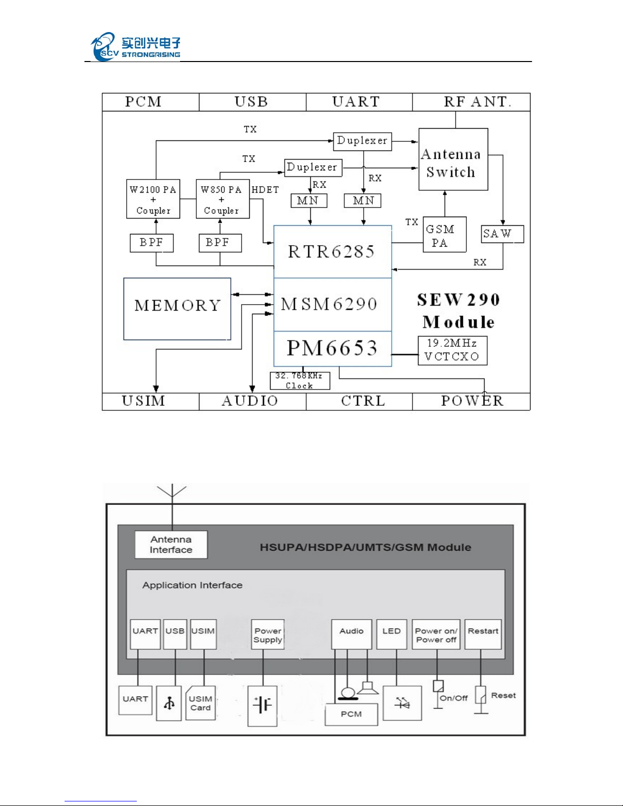
2Module Introduction
Please refer to Figure 2-1 for SEW290 module’s principle diagram and Figure 2-2 SEW290 Module’s
application diagram
SEW290 WCDMA Module
10
Figure 2-1 SEW290 Module’s principle diagram
SEW290 module is WCDMA wireless 3G module based on Qualcomm’s MSM6290 platform.The module
adopts 37PIN stampt-hole, it applies for WCDMA and GSM network and supports
GSM850/GSM900/GSM1800/GSM1900/WCDMA2100MHz/WCDAM850MHz
Figure 2-2 SEW290 Module’s application diagram

SEW290 WCDMA Module
11
3PIN Definitions
SEW290 module adopts stamp-hole welding method, totally 37 PINs. The distance among the pins is 0.5mm.
See the descriptions of PINs in figure 3-1. Please refer to table 3-1 for the key voltage of each pin.
Figure 3-1 Descriptons of PINs
SEW290
GND 37
1VREG_USIM
USIM
GND 36
2USIM_RST GND 35
3USIM_CLK
LED
SIG_LED 34
4USIM_DATA
PCM
PCM_DIN 33
5GND PCM_CLK 32
6EAR2_P
AUDIO
USB
USB_DM 31
7EAR1_P USB_DP 30
8EAR1_N ON/OFF 29
9MIC2_P
UART
PCM_SYNC(/DS
R) 28
10 MIC1_P PCM_DOUT(DC
D) 27
11 MIC1_N /DTR 26
12 GND /RTS 25
13 /PON_RESET RI(WAKEUP_OUT) 24
14 VBUS
POWER
TXD 23
15 VCHG RXD 22
16 VBAT /CTS 21
17 V_MSME_1V8 GND 20
18 VCC_PA
ANT
RF_ANT 19
Table 3-1 36PIN Definitions
Function PIN
Number Signal Name I/O Basic Function Remark
USIM
interface
1 VREG_USIM O USIM card power3V/1.8V
2 USIM_RST O USIM card reset
3 USIM_CLK O USIM card clock
4 USIM_DATA I/O USIM card data
Audio
6 EAR2_P O Audio output 2+
7 EAR1 P OAudio out
p
ut 1+
8 EAR1_N O Audio output 1-
9 MIC2_P I Audio input 2+

SEW290 WCDMA Module
12
10 MIC1_P I Audio input 1+
11 MIC1_N I Audio input 1-
Reset 13 /PON_RESET I Module reset Active low
Power
14 VBUS I USB power 3.4V-5V
15 VCHG I Charge power
16 V_MAIN I Work power 1 3.4V-4.2V
17 V_MSME_1V8 O Refer to 1.8V outout for 1.8V
18 V_MAIN I Work power 2 3.4V-4.2V
29 ON/OFF I Power on/off enabled
1.8V,Active low
UART
21 /CTS I UART clear to send 1.8V,Active low
22 RXD I UART receive data input 1.8V
23 TXD O UART transmit output
1.8V
24 RI O Module wake up signal 1.8V , same with the
wake_up pin
25 RTS O UART ready for receive 1.8V,Active low
26 /DTR I UART data terminal ready 1.8V,Active low
PCM
27
27
PCM_DOUT
()
DCD
O PCM data output 1.8V,same with the DCD
Pin
28
28
PCM_SYNC
()
/DSR
O PCM sync 1.8V, same with the /DSR
Pin
32 PCM_CLK O PCM clock 1.8V
33 PCM_DIN I PCM data input 1.8V
USB
interface
30 USB_DP I/O USB data+
31 USB_DM I/O USB data-
WAKE
UP
24 WAKEUP_OUT
O Module to wake up the host 1.8V, same with the RI
p
in
LED 34 SIG_LED O Module working status
indicator
Antenna 19 RF_ANT I/O Antenna interface
Ground
5、
、
12 20
、、
35
36、37
GND
SEW290 WCDMA Module
13
4Descriptions of Hardware Interfaces
4.1 Description
This section describes the function interfaces and usage of SEW290 module in details, and provides the
designing sample.
Power and Reset
UART
USIM
Audio
PCM
USB2.0
Antenna
Remarks: In the system, the module layout should be far away from high-speed circuit, switch power, power
transformer, large power inductor, or single chip microcomputer’s clock circuit.
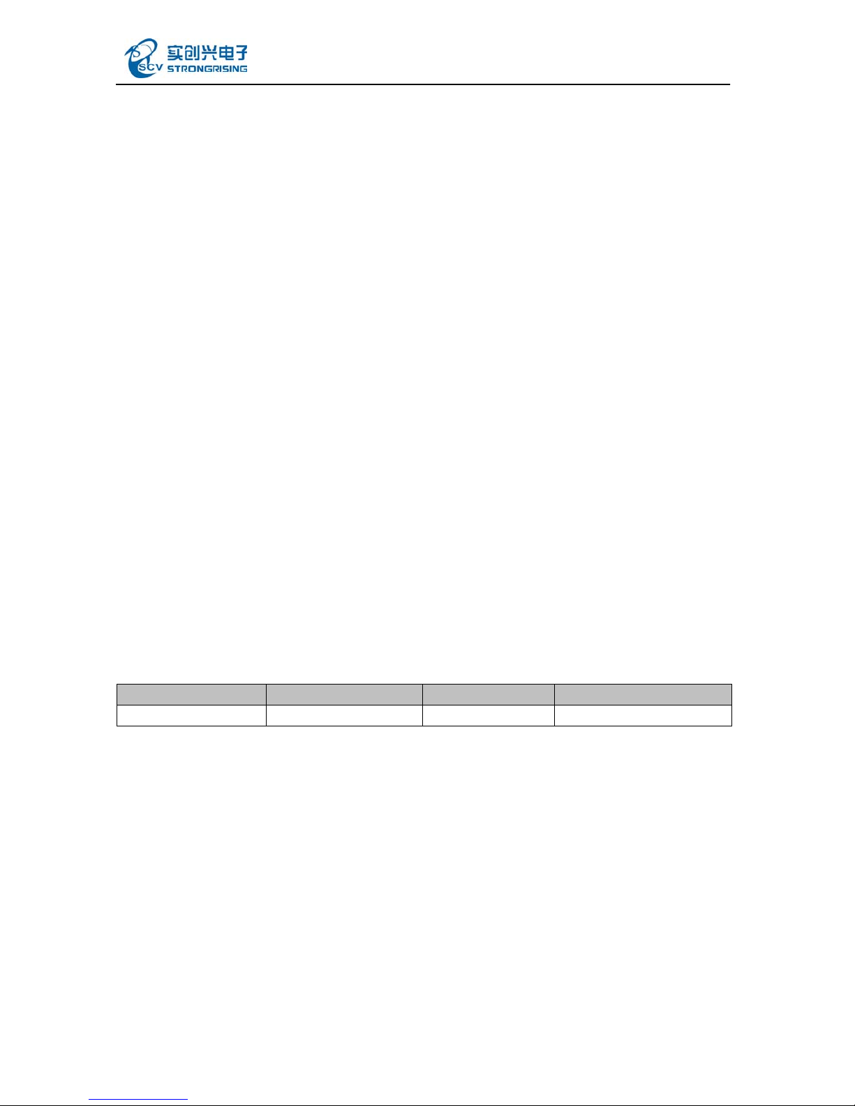
4.2 Power and Reset
4.2.1 Power Design
The module could work under two modes: 1. powered by power adaptor; 2. powered by battery.
The EUT was suppliped by a special supply unit,which is connected to a pc via a usb port ,this
supply unit could be recognised as a power supply.The EUT worked at 3.4~4.2V DC.
The power could be directly supplied by external power, which is directly added to V_MAIN and satisfy the
voltage in the table 4-1. The external power could be power adaptor, battery, USB power convertor, etc. It’s
recommended that the safe power current is 2A to satisfy the GSM and GPRS mode.
Charge input: For some application with Li-battery, the Li-battery charge manage was embedded in Module,
please note the input charge voltage should be DC :5V±0.5V
Table 4-1 Voltage Features
Classification Min. Typical Max.
Input voltage 3.4V 3.8 V 4.2 V
The supply power of Module should be DC from 3.3V to 4.2V,please refer to the following schematic to
design the power of Module:
SEW290 WCDMA Module
14
Power-on
The module could be turned on in the following method.
After the module is powered off, and then provide a 3000-4000ms low level pulse to ON/OFF PIN.
Power-off
To turn off the module, provide a 3000-4000ms low level pulse to ON/OFF PIN as the module is powered on.
V_MSME_1V8
SEW290 contains V_MSME_1V8 pin with limiting regulator function to supply power to the module external
circuit.The voltage of this pin with the BSP and Memory comes from the same voltage regulator.Only when the
module is powered on,this pin has voltage output.the normal output voltage is 1.8V.User should active the
current of this pin as little as possible(usually less than 10mA).
Generally,it's suggested that this pin used for Chip pins level matching demand pullup.
In order to ensure that the module data can be kept safely and for module data security, do not Cut off the power
supply when module is running.User should use the ON/OFF pin or AT commands for ON/FF operation.
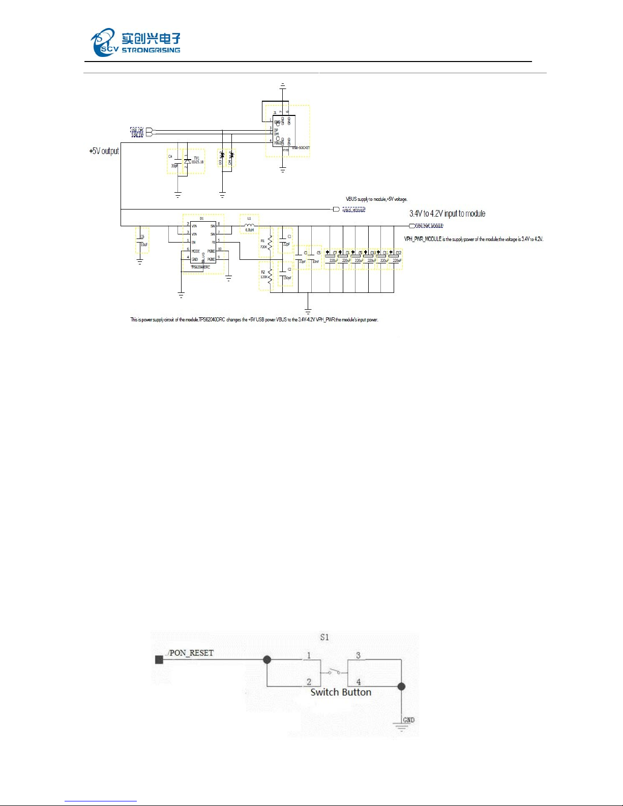
4.2.2 Reset
You could turn off the module firstly and then turn it on to reset the module when the module software stops
responding.Provide a 50~200ms low level pulse to the /PON_RESET pin as the module can reset.
Please refer to figure 4-1 for the module reset external circuit.
figure 4-1 Module reset external reference design circuit

SEW290 WCDMA Module
15
Remarks:this pin is sensitive to interference.The external circuit line length of this pin should no longer than
2cm,otherwise the interference may active the reset pin.
4.3 UART
The module provides an integrated full duplex full flow control UART interface, whose maximal data rate is
230.4kbps, typical value is 11.5kbps. External interface is 1.8V CMOS level signal, input is compatible.
Remarks:to support the UART function the module software needs update.
When using SEW290 module’s URAT interface to communicate with PC or MCU,please pay attention to TX
and RX direction, especially, note that SEW290 UART interface only supports 1.8V. Therefore, the triode is
usually used to realize level conversion for non 1.8V external UART. See figure 4-2, the resistance is just for
reference. Please recalculate when designing it.
Figure 4-2 UART interface external reference design circuit
4.4 4.4 USIM Card
SEW290 module supports the ClassB-3V and ClassC-1.8V USIM card, which includes 4 pins at the end.
USIM card PCB layout should be close to the module as much as possible to avoid the interference of
reading/writing USIM card from other sources.It’s strongly recommended to add ESD protection component
when designing UIM circuit. See ESD protection component D2 in figure 4-3.
NOTE: Considering the difference on the output current from DATA pin of different cards, a 10K resistor
should be used to pull up DATA pin to V_CARD(VREG_USIM).

SEW290 WCDMA Module
16
Figure 4-3 USIM card circuit reference design diagram

SEW290 WCDMA Module
17
4.5 Audio
The module provides two audio inputs and two audio outputs through stamp-hole PIN. The module also
provides 2 microphone interfaces and only one pair I/O works at the same time. Two audio outputs include 1
receiver differential output and 1 headset single-end output.
Microphone
It provides two microphone interfaces MIC1 and MIC_P, among which MIC2_P is differential interface.
These two microphone inputs are internally coupled in AC domain and added a 1.8V offset voltage to directly
connect the microphone.
Earpiece
It provides two earpieces: EAR1 & EAR2_P, and EAR1 is differential interface with 32Ωresistance;while
EAR2_P is single-ended interface with 32Ωresistance.
Design of audio interface on the receiver
Select the microphone with the sensitivity lower than -52dB since the output power for EAR1 is 50mW and the
max. gain in MIC1 can reach up to 52dB. The level of MIC_1P is about 1.8V.
Note: if other kind of audio input method is adopted, the input signal should be within 2V. If the signal voltage is
lower than 2V, then the pre-amplifier should be added. If the signal voltage is higher than 2V, then network
attenuation should be added.
Design of audio interface on the earpiece
Select the microphone with the sensitivity lower than -52dB since the output power for EAR2_P is 8.8mW and
the max. gain in MIC2_P can reach up to52dB. The level of MIC_P is about 1.8V. The design is almost the
same.
If EAR2_P is used for hands-free speaker output, an audio power amplifier should be added.
Figure 4-4 Audio external circuit reference design diagram

SEW290 WCDMA Module
18
4.5 PCM
SEW290 Module's PCM interface provides PCM_CLK, PCM_SYNC, PCM_DIN, PCM_DOUT four
pins,supports 2.048MHz clock rate and 8K frame rate. PCM clock in the module will stop when the module go
into a sleep mode. PCM interface provides signal transmission application such as voice for an external Bluetooth
device.
The module must work on the Master state cause the PCM_SYNC signal and PCM_CLK signal must output when
PCM master.The PCM device connected to module PCM can only work on Slave state.
Figure 4-5 Module PCM working mode diagram

SEW290 WCDMA Module
19
Figure 4-6 Module PCM working time sequence diagram
4.6 USB 2.0
The module provides a USB2.0 high speed (480Mbps)interface, which is composed of VBUS, D+ and D-. The
module’s external circuit could connect directly with USB signal connector, but during the design process, try to
add ESD protection component to avoid damage. D12 in Figure 4-7 shows USB2.0 ESD protection component
with the junction capacitance is smaller than 3pF. VBUS could connect directly with VBUS at external host end.
The USB recommended voltage is: 3.0-5.6V, typical 5V.
Figure 4-7 USB2.0 external circuit reference design diagram
Table of contents
Popular Control Unit manuals by other brands

TECALEMIT
TECALEMIT WONDERBOX Gen II US110500700 Quick Guide, Hardware Installation

SP Controls
SP Controls PixiePlus PXE-DCM PLUS installation guide

Adtech
Adtech PAM59 instruction manual

Bosch
Bosch Rexroth PSI 6500 Series technical information

Helvest Flex
Helvest Flex KB800 operating instructions

STAUFF
STAUFF STA-CK-305 instruction manual

Brizo
Brizo Virage T75P530-GL manual

LEGRAND
LEGRAND LEXIC 074 03 quick start guide

A.R.I.
A.R.I. K-060VB M1 Installation operation & maintenance

YOKOGAWA
YOKOGAWA AQ2200-111 user manual

Bray
Bray FlowTek F30 Series Installation, operation and maintenance manual

FPS
FPS 9650 Series Installation and maintenance manual


