Strong Super Trouper User manual

FOLLOW SPOTLIGHT
INSTRUCTION MANUAL
4350 McKinley Street • Omaha, Nebraska 68112 USA
Tel (402) 453-4444 • Fax (402) 453-7238 • www.strong-lighting.com
Equipment Type 7201156 • Rev. October 2010


PREFACE
THESTRONGXENONSUPERTROUPER®isadirectcurrentfollowspotlight
systemcompletewithaxenonlamphouse,powersupply,opticalsystem,andaoorstandandyoke
assembly.Anoptionalsix-color,selfcancellingboomerang(OrderNo.7201188;seeFigure7)may
beorderedwithnewequipment,oritcanbeaddedatalaterdate.
ONLY THE SPECIAL XENON POWER SUPPLIES manufactured by Strong
Internationalcanbeusedwiththexenonspotlight.
Forinstallationandoperationofthepower
supply,seetheinstructionmanualfurnishedseparately.
THEXENONLAMPHOUSEutilizesadeepellipsedichroicmetalreectordesignedto
operateinaxedpositionwithahorizontallymountedxenonbulbasthelightsource.Aheatlteris
locatedinthefrontofthelamphousetoreducetheheatattheopticalsystemandcolorboomerang.
ONLY XENON BULBS designed for horizontal operation should be used in this
spotlight.Thelamphouseisdesignedforusewiththestandard2000watthorizontaltheatrebulb,
andanoptionalAdapterKit(OrderNo.7201192)allowsuseof1000and1600wattbulbs.Seethe
listinginthismanualfortheapprovedtypesandnecessaryadapters.
ADJUSTMENTCONTROLforpositioningthexenonbulbislocatedattherearof
thelamphouse.Theadjustmentsareforthehorizontal,vertical,andfocuscontrolofthebulb.
THELAMPHOUSE INSTRUMENTPANELisequipped withan ammeterand
runningtimemeter.Theammeterindicatestheoperatingcurrentofthelamp,andtherunningtime
meterrecordsthenumberofhoursthelamphasoperated.Thexenonbulbisignitedandextinguished
byuseoftheLAMPswitchmountedontheinstrumentpanel.
THELAMPBLOWER,internallywiredinthelamp,operateson115V.ACandis
requiredtokeep thesealson thebulbatasafeoperatingtemperature. Thisblower willoperate
continuouslyuntilpoweristurnedoffatthemainlineswitchtothexenonpowersupply.Anair
owswitchinthelamphousepreventsoperationofthexenonlampiftheblowerisnotoperating,or
ifairowisinadequate.Ifadditionalcoolingisrequired(i.e.50Hertzpowersource),anoptional
ExhaustBlowerAssembly(7201036;seeFigure8)maybemountedtothetopofthelamphouse.
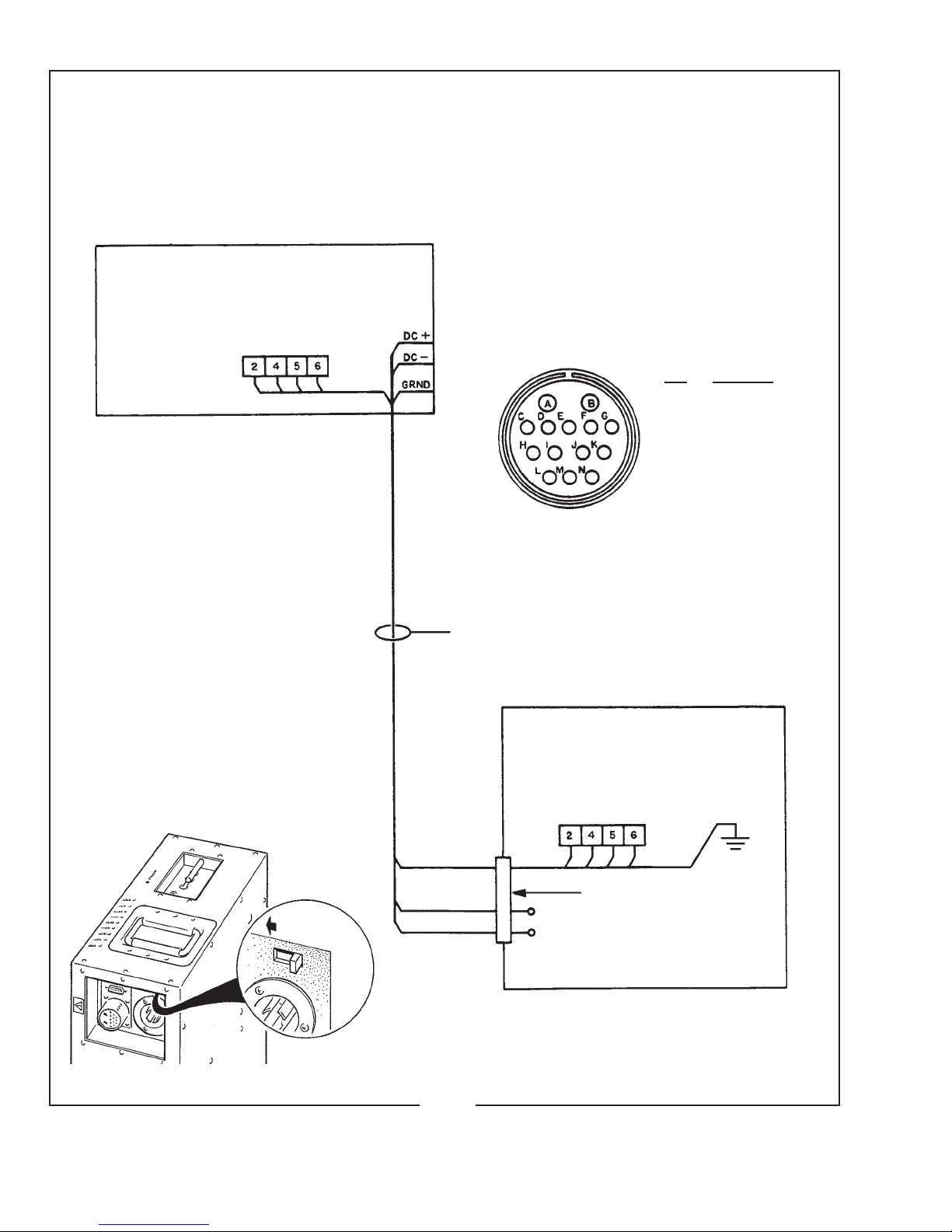
THELAMPHOUSEissuppliedwitha11foot(3.35m)cablecontainingthetwoDC
leads,thegroundlead,andallACcontrolleads.Thecableterminatesinamultiple-pinMSconnector
tomatetoacorrespondingreceptacleonthexenonpowersupply.
WHENTRANSPORTINGthefollowspotlight,itisrecommendedthatthexenonbulb
beremovedfromthelamphouseandplacedinitsoriginalshippingcartonwiththeprotectivecover
onthebulbtopreventbreakage.
XST/001

LAMPHOUSE - POWER SUPPLY
Interconnection Diagram
LAMPHOUSE
(Connections Pre-wired)
MS CONNECTOR
Pin Wire No.
A DC-
B DC+
C 2
E 4
F 5
G 6
M Grnd
Lamphouse
Cable Assembly
XENON
POWER
SUPPLY
MS Connector (pre-wired)
DC+
DC-
XST/002
SYSTEM MUST BE GROUNDED
All wiring must conform to local codes;
shield lamphouse cable in conduit if
required.
Check Slide Switch (below) on Power
Supply for correct “SPOT” position.
Slide to LEFT

XST/003
INSTALLATION AND SETTING UP SPOTLIGHT
THEXENONSUPERTROUPERisshippedinsectionswhichmustbeassembled.
TheFoldingBaseStandAssembly65826000(seeFigure6)isshippedcollapsed,andrequiresonly
foldingdownandpinningthefourbaselegs.
WHENINSTALLEDinapermanentlocation,thelevelingfeetmustberemoved,and
theclearanceholesinthebaselegbracketsusedforhardware(usersupplied)toboltthebasetothe
oororplatform.Ifitisdesiredtohavetheunitportable,whenoperating,thelevelingfeetmustbe
adjusteddownuntiltheweightofthespotlighthasbeenshiftedfromthecasterstothelevelingfeet.
THEINNERTUBEandsupportyokehasthreeholestopermitadjustingtheheightof
thespotlight.Thethreeholesareonfour-inchcentersandwillallowanopticalheightofapproximately
53inches,57inches,and61inchesaboveoorleveltotheopticalcenterofthelamphouseandlens
system.Thelevelingfeetmaybeadjustedthroughanadditionaltwoinchrange.Inserttheheightloca-
tionpin(Figure5,Item16)throughtheholeintheoutertubeandoneoftheholesintheinnertube.
THEHORIZONTALSWINGandverticaltiltlockingknobsareontherighthand
(operating)sideoftheyokeassembly.Tightenbothoftheselockingdevices(Figure6,Items19&
21)securelybeforeattemptingtoplacethelamphouseandlenssystemonthesupportyoke.
PLACETHELAMPHOUSEandlenssystemontheyokeassembly(Figure6,Item4),
withthespotsizecontrolhandletotherighthand(operating)side,thesameasthelockingcontrols
ontheyoke.Lineupthefourmountingholesinthebottomofthebaserailwithfourslottedholesin
thesupportyokeandsecurewiththefour5/16-18wingscrews.Thereare(2)setsoffourmounting
holestoinsurecorrectbalanceofthespotlightwithorwithouttheoptionalcolorboomerang.An
optionalCounterweightKit(7201191)isalsoavailableforsettingconcisebalanceadjustments.
THEOPTIONALCOLORBOOMERANG(7201188)mountstothefrontopening
oftheopticalsystemonthreestudsprotrudingfromthefrontoftheopticalsystemhousing.Secure
theboomerangusingthe(3)screwsprovided,andinstallthesafetycablebetweentheboomerang
housingandthespotlightframe.
ATTACHTHELAMPHOUSECABLECONNECTORtothereceptacleonthexenon
powersupply.Alignthepinsbeforetighteningthelockingring.Donotenergizethepowersupply
beforerstcompletingthebulbinstallationprocedure.
CHECKTHE“CONS/SPOT”SLIDESWITCHonthexenonpowersupplycabinet
andverifythatithasbeenplacedintheappropriate“SPOT”position.Seetheillustrationonthe
insidefrontcoveroftheXenonPowerSupplyinstructionmanual.

SAFETY PROCEDURES
THEXENONBULBishighlypressurized.Whenignited,thenormaloperatingtemperature
ofthebulbincreasesthepressuretoalevelatwhichthebulbmayexplodeifnothandledinstrictaccordance
tothemanufacturer’soperatinginstructions.Thebulbisstableatroomtemperature,butmaystillexplodeif
droppedorotherwisemishandled.
REFERbulbreplacementandservicetoQUALIFIEDPERSONNELwithadequateprotec-
tiveclothing(faceshield,cleancottongloves,welder’sjacket).Forroutinelamphouseservice,observethe
followingrules:
1. Allowthebulbtocooltoroomtemperaturebeforeopeningthelamphouse.Putonprotectiveclothing
describedabove.
2. De-energizethexenonpowersupplyattheACsourcebeforeopeningthelamphousecompartment.
3. Whenpossible,encasethe bulb in its protectivecover whencleaning orservicing the lamphouse
interior.Thebulb,whenoutsidethelamphouse,mustbeencasedinthecover.
4. Cleanthebulbafterithascooledtoroomtemperature.Donottouchthequartzenvelopeofthebulb;
ngerprintswillburninandcreatehotspotswhichmayshortenbulblife.Ifngermarksaremade,
theyshouldbecarefullyremovedwithmethylalcoholandcottonpriortobulboperation.
5. Neverviewanignitedbulbdirectly.BLINDNESSORPERMANENTEYEDAMAGEMAYBE
INCURRED.
6. UseonlyxenonbulbsdesignatedasOZONEFREE.Whenpossible,ventthelamphouseexhaustto
outsideatmosphere.
7. Maintainthelamphousebloweringoodoperatingcondition.Keeptheblowerinletcleanforunre-
strictedairow.
8. Toinsuremaximumbulblife,operatethelamphouseblowerandtheexhaustsystemforat leastten
minutesafterextinguishingthebulb.
9. Ifreturningabulbforwarrantyadjustment,packitinitsoriginalshippingcontainer.Completeand
returnallrequiredwarrantyinformation.
10. Disposeofexpiredbulbsthatarebeyondwarrantyinthefollowingmanner:Wrapthebulbtightly
inseverallayersofcanvasorheavycloth.Placeitonahardsurfaceandshattertheenvelopewitha
sharphammerblow.DONOTplaceanunshatteredbulbinanordinaryrefusecontainer.
11. DONOTPERMITUNAUTHORIZEDPERSONNELTOPERFORMORATTEMPTANYPHASE
OFXENONBULBHANDLINGORSERVICE.
Cathode End Cap
Envelope
Anode End Cap
Anode Pin
Seal Anode
Cathode
Trigger Wire Cathode Pin
Seal
XST/004

1.Fade-OutMechanismControlLever
2.MaskingShutter(Chopper)ControlLever
3.IrisControlLever
4.BoomerangMountingStud,Upper*
5.SpotSizeControlHandle
6.BoomerangMountingStud,Lower*
XST/005
2
13
4
5
6
7
8
9
10
11
12
7.SpotFocusControlKnob
8.LevelingFoot
9.HeightAdjustPin
10.HorizontalSwingControlLever
11.VerticalTiltControlLever
12.LiftingStrap
*ColorBoomerangoptional;seeFigure7

EXHAUST SYSTEM INSTALLATION
IFTHESPOTLIGHTisinstalledinaclosedbooth,itisrecommendedtoventthe
lamphouseexhausttooutsideatmospheretoremovetheheatfromthebooth.Anoptionallamphouse
topcoverplatewithanexhauststack(PartNo.7201222)maybeorderedfromStrongandinstalled
inplaceofthestandardtopcoverplate(seePartsList,Figure2,Item27).
THEEXHAUSTSTACKoftheoptionallamphousecoverplateisdesignedtota
six-inchdiameterduct.Theexhaustsystemmustbedesignedandinstalledisamannerastoelimi-
nateanypossibilityofadowndraftorofraindrippingintothelamphouse.Theexhaustfanmustbe
capableofremoving750linealfeetperminute(150cfm)ofairfromeachlamphouse.
TO PERMIT MOVEMENT of the follow spotlight, install a section of six-inch
diameter,non-ammable,exibleductingbetweenthelamphouseexhauststackandtheprojection
boothexhaustsystem.Twoscrewholesintheexhauststackcanbeusedtosecuretheductingwith
#6self-tappingsheetmetalscrews.
IFADDITIONAL BULB COOLING is required (i.e. 50 Hertz power source), an
optionalExhaustBlowerAssembly(PartNo.7201036;seeFigure8)maybemountedtotheexisting
topcoverofthelamphouse.Whenconnectingtheblowerleads,makecertainthewiresaredressed
behindthereectorsupportcastingtopreventheatdamage.Thisblowerassemblyexhaustsintothe
surroundingairanddoesnotallowconnectiontoaductedexhaustsystem.
THERADIATIONfromsomexenonbulbscanconverttheoxygeninthesurrounding
airtoozone.Inlargequantities,ozonecanendangerhealth,butitspontaneouslychangesbackinto
oxygeninaveryshorttime,especiallyifitmixeswithalargevolumeofair(asinanauditorium,
arena,oroutdoors).Mostcurrentlymanufacturedxenontheaterbulbsareclassiedasozone free
anddonotreleaseozone.
XST/006

1.LAMPSwitch(ON-OFF)
2.Ammeter
3.AirIntake,Blower
4.Cover,BulbAdjustControls
5.TopCover,Lamphouse
6.ElapsedHourMeter
XST/007
12
3
4
5
6

XST/008
1000, 1600 WATT BULB INSTALLATION
Requires optional Bulb Adapter Kit 7201192
65960000* 65131000
4100180
65199000
REAR OF LAMPHOUSE
OBSERVE CORRECT POLARITY
65117000*
4110750
65198000 65152A00
65151000
65148000*
1000 Watt Operation: 50 Amperes Nominal
DO NOT EXCEED 58 AMPERES
1600 Watt Operation: 65 Amperes Nominal
DO NOT EXCEED 70 AMPERES
PartNo. Description
65117000 BulbSupportYoke
65131000 Anode(+)ContactClamp
65148000 Cathode(-)ContactClamp
65151000 RetainerPlate
65152A00 Thumbscrew(2req’d.)
65198000 CathodeAdapter
65199000 AnodeAdapter
65960000 RearBulbSupportCollet
4080870 ClampingScrew(for65131000&65148000)
4100180 SetScrew,AnodeAdapter
4110750 BulbSupportMountingScrew
4250373 LeadMountingScrew(for65131000&65148000)
NOT SHOWN
65948000 Negative(-)LeadAssembly,29"(ClamptoShunt)
65966000 Positive(+)LeadAssembly(incl.65131000)
* Replace Collet, Front Bulb Support, and
Cathode Clamp before installing bulb.

BULB INSTALLATION
CAUTION:OBSERVEALLSAFETYPROCEDURES.Putontheprotectiveface
mask.Wearcleancottonglovestopreventmarkingthequartzenvelopeofthebulbwithngerprints.
REMOVETHE TOP COVER of the lamphouse by removing the four Holt head
(tamperproof)screwswiththespecialscrewdriverprovided.
NOBULBADAPTERSarerequiredtoinstallthe2000wattbulbintheXenonSuper
Trouperlamphouse.Componentsandadaptersrequiredtoinstallthe1000wattor1600wattbulb
inthelamphouseareavailableinanoptionalAdapterKit(PartNo.
7201192)
.SeetheBulbAdapter
illustrationonthefacingpageforthecorrectadaptersandmethodofassembly.
DISMOUNTANDREMOVEthefrontbulbmountingringassemblyfromtheairduct
castinginfrontofthereectorandreplaceitwiththesmallerbulbsupportyokecastingincludedin
the7201192BulbAdapterKit.Installthe65148000cathodeclampinplaceofthestandard2kW
clamp.Removetherearbulbsupportcolletassembly(nylonrodandbrasssocket)fromthebulbfocus
assemblybehindthereectorandreplaceitwiththecolletassemblyincludedintheBulbAdapterKit.
ASSEMBLETHEREQUIREDADAPTERStothe1000or1600wattbulbpriorto
insertingthebulbintothelamphouse.Beverycarefulnottoapplyanystrainonthequartzenvelope
wheninstallingadapters.
Handlethebulbbyitsmetalendcapsonly.Screwthethreadedcathode
adapterontothenegativestudsoitseatsrmlyagainsttheshoulderofthecathode(-)endcap.
Applytorqueusingthepinsonthecathodeendcap.Sliptheanodeadapterwithsetscrewoverthe
positivestud,uptotheshoulderoftheanode(+)endcap.Tightenallfastenerssecurelytoinsure
agoodelectricalconnection.
REMOVETHEPLASTICPROTECTIVECOVERfromthexenonbulbonlyifnec-
essary.Insertthebulbthroughthetopofthelamphouse,betweenthereectorsupportandthefront
casting.Passtheanode(+)endofthebulbthroughtheholeinthereector,takingcarenottotouch
thesurfaceofthereector.
INSERTTHEANODEADAPTERSTEMof1000and1600wattbulbsintotherear
supportcollet.Thestemmustbeinsertedintothesocketasfaraspossibletopermitfullfocustravel
ofthebulb.Placethestemofthecathodeadapterintofrontbulbsupportyoke,pivottheretaining
platetoitsclosedposition,andtightenthe(2)thumbscrews.Tightenthesocketheadclampingscrew
intheanodecontactsecurelytoinsureagoodelectricalcontact.
INSTALLTHECATHODELEADCONTACTovertheendofthecathodeadapter
uptotheshoulderofthecontactandtightentheclampingscrewsecurely.Dresstheleadinfrontof
theairducttominimizetheshadow.
XST/009
1000&1600WattBulbInstallation

THE2000WATTbulbmountingcomponentsincludeashockmountsupportatthefront
ofthelamphouse.Insertthe2000wattbulbthroughthetopofthelamphouse,passingtheanode(+)
endthroughtheholeinthereector.Passtheanodepinasfaraspossibletotherearofthelamphouse
topermitslidingthecathode(-)endcapthroughtheringoftheshockmount.Temporarilyremoving
the65131000anodeclampfromthebrasssocketofthecolletallowsaddedclearanceforthebulb.
Gentlyrotatingorturningthebulbwhileslidingthecathodeendcapthroughtheshockmountwill
slightlycompressthecoilspringandpreventstrippingthespringfromitschannelinthering.
REPLACETHEANODECLAMPovertherearbulbsocket.Inserttheanode(+)pin
ofthebulbintotherearsupportcollet,andrmlytightenthesocketheadclampingscrew.Slidethe
65410000cathodecontactclampoverthecathode(-)pinandtightensecurely.
ANALTERNATE METHOD of installing the 2000 watt bulb is to dismount the
83748000shockmountringfromthefrontbulbsupportassemblybyremovingthe4100620socket
headclampingscrew.Slidetheringoverthecathode(-)endcapofthebulb,andinstallthebulbby
insertingtheanode(+)endcapthroughthereectorcenterholeandseatingtheanodepinintothe
rearsupportcollet.Remounttheringtothe83364000basebracketofthefrontbulbsupportusing
thesocketheadscrew.DONOTdismountorrepositionthefactory-alignedbasebracket.Secure
theanode(+)clampingscrew;installandtightenthecathode(-)contactclamp.
THESOCKETHEADSCREWwhichmountsthe83748000bulbsupportringtothe
83364000basebracketmustbetightenedsecurelyenoughtoclamptheuprightbulbsupportringin
avertical(90°)positionandpreventitstiltingforwardorbackasthebulbisfocused.Theendcapof
thebulbshouldtouchonlythecoilsofthe83410000shockmountspringtoallowthebulbtoslide
forwardandbackwithaminimumoffrictionandno stressonthequartzenvelope.
OBSERVETHEPOSITIONoftheTriggerWireonthexenonbulbrelativetothepoint
wherethebulbpassesthroughthecenterholeofthereector.Somebulbmanufacturersattachone
endofthetriggerwiretotheanodeendcap;ifthistriggerwireapproachesthereectortooclosely,
theDCcurrentmayfollowthispathtogroundandpreventbulbignition.Inthisevent,detachthe
triggerwirefromtheanodeendcapandloopitaroundthebulbousportionoftheenvelopeasillus-
tratedonthelinedrawingatthebottomoftheSAFETYPROCEDURESpage.
ITISRECOMMENDEDtoestablisharoutineforperiodicallycheckingallelectrical
connectionsfortightness,particularlythoseatthebulb.AlooseconnectionintheDCcircuitwill
causefailureofthecontactsandleads,andmaydestroythebulb.
THEREFLECTORisopticallypositionedatthefactory.Donotalterthepositionof
thereectorbyadjustingthethreadedtierodlocatedintheuppercornerofthelamphouse.
XST/010
BULB INSTALLATION (continued)
2000WattBulbInstallation

XST/011
4080870
6541000
4250503
4110750
83748000
65131000
4080870
65844000
REAR OF LAMPHOUSE
OBSERVE CORRECT POLARITY
PartNo. Description
65131000 Anode(+)ContactClamp
65410000 Cathode(-)ContactClamp
65844000 RearBulbSupportCollet,2kW
83364000 FrontBulbSupportBaseBracket
83410000 CoilSpring(inside 83748000; not shown)
83748000 FrontBulbSupportRing
4080870 ContactClampingScrew
4100620 SupportRingClampingScrew
4110750 BulbSupportBracketMountingScrew
4250503 LeadMountingScrew
NOT SHOWN
65948000 Negative(-)LeadAssembly,29"(ClamptoShunt)
65966000 Positive(+)LeadAssembly(incl.65131000)
2000 Watt Operation: 75 Amperes Nominal
DO NOT EXCEED 90 AMPERES
2000 WATT BULB INSTALLATION
Position Ring at 90° (as shown) and
tighten 4100620 Clamping Screw
DETACH & DISCARD ANY FACTORY-MOUNTED
LEAD CONNECTED TO BULB END CAP
SHORT 2000 WATT (Type “HS” ) BULB NOT
USED IN XENON SUPER TROUPER
8336400

OPERATION
REMOVETHEPLASTICCOVERfromthexenonbulb.Do notignitethelampwith
theprotectiveshippingcoveronthebulb.
AGLASSHEATFILTERissuppliedtoreducethetemperatureattheopticalsystem
andcolorgels.Thislterisanarrowglassstripthatcoversonlythecenterportionofthebeam.Insert
theheatlterinthebracketprovidedontheinsideofthelamphouseatthefrontopening(seeFigure
2,Item2).Placethelterinpositionwith the coated surface facing the bulb.Thecoatedsurfaceis
indicatedbyasmallXXorothermarking.Topreventdamagetoopticalsystemcomponents,do not
operatethespotlightwiththelterremovedorreversed.
SECURETHELAMPHOUSECOVERwiththe(4)tamperproofscrewsusingthe
specialscrewdriverprovided.Thecovermustbesecurelyinpositiontoactuatetheinterlockswitch
andpermitlampignition.
CLOSETHECIRCUITBREAKERonthexenonpowersupplytoenergizethepower
supply.Theblowersinthepowersupplyandinthelamphousewillstart;thelamphouseblowerwill
actuatetheairintakeinterlockswitchtopermitbulbignition.Thelampandpowersupplyblowers
willoperatecontinuouslyuntilthexenonpowersupplyisde-energized.
PLACETHELAMPSWITCHintheONpositionandthexenonbulbwillignite.
Allowafewminutesforthecurrenttostabilize,andreadthelamphouseammeter.Thebulbmust
beoperatedwithinthecurrentrangespeciedbythebulbmanufacturer.Therangesforthexenon
bulbsapprovedforusewiththeXenonSuperTrouperareasfollow:
WATTAGE NOMINALCURRENTDONOTEXCEED
1000 50A. 58A.
1600 65A. 70A.
2000 75A. 90A.
ADJUSTTHEPOWERSUPPLYasinstructedinthepowersupplymanualforthe
correctoperatingcurrent.Thecurrentsettingmustbeincreasedintimetocompensateforbulbaging,
butdo not,atanytime,exceedthemaximumcurrentrating.
REMOVETHEREARCOVERPANEL(twoblackplasticpull-typeknobs)toexpose
thebulbpositionadjustmentcontrol.
THECENTERSECTIONofthecontrolisathreadedmemberthatfocusesthebulbin
relationtothereector.Turningthisadjustmentmovesthebulbonthehorizontalplane,intoorout
ofthereector.Rotatingthissectionclockwisemovesthebulbawayfromthereector.Thesmall
knurledscrewtotheleftofthissectioncanbetightenedtolockthefocusingmechanisminplace
afterthebulbalignmentprocedurehasbeencompleted.
XST/012

THETHUMBSCREWStotheleftandrightofthefocusingcontrollockthehorizontal
andverticalpositionofthebulb.
TWOMETHODS,detailsfollowing,arerecommendedtoalignthebulbinorderto
projectthebestlighttothestage.
MOVETHESPOTSIZECONTROLHANDLEonthelargelenscarriagetothe
forwardmostpositiontoprojectthesmallestspotpossible.Settheiris,choppers,anddimming
controltotheirfullopenpositions.Projectthespottoawallorsimilaratperpendicularsurface
oppositethespotlightposition.
TURNTHE CENTER FOCUS CONTROL counterclockwise until a small black
spotisprojectedonthewall.Itmaybewelltorunthisadjustmentbothdirectionstopermitpositive
identicationofthedarkspot.
LOOSENTHETWOTHUMBSCREWStotheleftandrightofthefocuscontrol
justenoughtopermitmanualmovementofcompletecontrolassembly.Movethecontrolassembly
aroundthetwothumbscrewsandobservethesmoothdarkshadowofthebulbelectrodeinsidethe
shadedcircleofthereectorcenteropening.Theshadowoftheelectrodemustbecenteredinthe
projectedopeningofthereector.
MOVETHECONTROLASSEMBLYaroundthethumbscrewsuntilthedarkelec-
trodeshadowisasroundaspossibletoproject.Itmaybenecessarytoagainrotatethefocuscontrol
todenetheelectrodeshadow.
AFTERTHEELECTRODESHADOWisaseven aroundthe outsideas possible,
tightenthetwothumbscrewstolockthisadjustmentinplace,androtatethefocuscontroltoobtain
thebrightestlightwiththebestlightdistribution.Turnthespotfocuscontrolknob,locatedonthe
frontofthelensmechanism,tosharpentheedgeofthespot.
THESECONDMETHODofaligningthexenonbulbistoprojectthespottothestage,
andusingthebulbadjustmentcontrols,obtaina“hotspot”intheprojectedspot.Centerthis“hot
spot”intheprojectedspotbymovingtheentirecontrolsectionaroundthetwothumbscrews.Once
Focus Lockscrew
Thumb Screw Focus Control
BULB ADJUSTMENT CONTROLS
XST/013

the“hotspot”iscenteredintheprojectedspot,locktheadjustmentcontrolinpositionwiththetwo
thumbscrewsandrotatethefocuscontroltoobtainaspotwithanevendistributionoflight.Turn
thespotfocuscontrolknobatthefrontofthelensmechanismtosharpentheedgeofthespot.
THISADJUSTMENTshouldnotbedisturbeduntilthexenonbulbisreplaced.At
thistimeitwillbenecessarytorepeatthealignmentprocedure.
REPLACETHEREARCOVERPANELoverthebulbadjustmentcontrolmechanism.
Secureusingtheplasticfasteners.
BECAUSEOFMANUFACTURINGTOLERANCESandnormalbulbaging,itmay
benecessarytooperateonelampatslightlyhigherorlowercurrentthanotherstobalancelightouput
betweenmultipleunits.Theseadjustmentsaremadeatthexenonpowersupply.
TOEXTINGUISHTHEARC,placethe LAMPswitch in theOFF position.The
blowerinthelamphousewillcontinuerunninguntilthexenonpowersupplyisde-energized.Allow
theblowertooperateandcoolthebulbforat leastveminutesafterextinguishing.Thismeasure
willprolongbulblife.
HANDLING THE SPOTLIGHT
GENERALLYTHEBESTPOSITIONfortheoperatortostandisnearthecenterof
thespotlight,ontherighthandside,althoughtheangleoftiltandthesizeoftheportholemayalter
thepositionforthemostconvenientoperation.
EACHOPERATORwill,afterafewminutesofoperation,generallydevelophisown
systemandpositionforoperatingtheunit.
THEHORIZONTALSWINGLOCKLEVERandverticaltiltlockleverlocatedon
thebaseassemblycanbesettogivethedesiredamountoffrictiononthespotlightswingtosuitthe
individualoperator.Anoptionalcounterweightassembly(PartNo.7201191;seeFigure7)allows
addingorremovingweightsforconciseadjustmentofthespotlightbalance.
THELENSCARRIAGEFRICTIONBRAKEisanylondragscrewandlocknutlocated
ontheoutriderofthelargelenscarriage(seeFigure4,Items16&17),andispresetatthefactory
formostsatisfactoryoperation.Individualrequirementsmayvary,andthebrakecanbeadjustedto
bestsuittheoperatorortoallowforasteepdownwardangle.Removethecolorboomerangandlens
mechanismhousing,loosenthenylonlocknutandtightenorloosenthescrewonthefrictionbrake
toapplythedesiredtension.Tightenthelocknutandreplacethehousingandboomerang.
XST/014

XST/015
OPERATION OF COLOR BOOMERANG
THEOPTIONALCOLORBOOMERANGisequippedwithsixcolorlterholders.
Additionallterholders(51928000&51376000)canbesuppliedbyyourStrongdealer.
TOOPERATE INDIVIDUAL COLOR FILTERS, lower thedesired lter selector
lever.Arockercatchlocatedinthecolordischousingholdsthelterinposition.
TORELEASEACOLOR,pusheitherlterreleasearmupwardorengageanother
color,thusreleasingthepreviouscolorautomatically.
NOTE:WHENPLACINGCOLORFILTERSintheboomerang,thelessdensecolors
(amber,pink)shouldbeplacedintheholderstowardtherearoftheboomerang(closertothearc),and
thoseofgreaterdensity(red,green)shouldbeplacedintheholderstowardthefrontoftheboomerang
(awayfromthearc).UseRoscoLux
®
(orequivalent)high temperaturelters.
COLORTEMPERATUREREDUCTIONFILTERS,requiredforusewithtelevision
andvideotape,areavailablefromtheatricalsupplydealers.
PROVISIONISMADEfor“stowing”colorholdersfortransport.Whenstowed,
thecolorholdersareprotectedfrombreakageorotherdamagecausedbymovingthespotlight.To
enableoperationofthecolorboomerang,detachthelowerthumbscrewsecuringthehingedportion
oftheboomeranghousingandfoldthepanelsupward.Thisallowsthecolorholderstodropintoa
“deployed”positionfornormaloperation.Anupperthumbscrewallowslockingthehingedpanels
intheupperposition.Toagainstowthecolorholdersfortransport,raiseallsixcolorholderstotheir
engagedposition,loosentheupperlockscrew,unfoldthehingedboomeranghousing,andsecurein
thelowerposition.
“Stowed” “Deployed”
Housing
Lockscrew
Mounting
Thumbscrew

OPERATION OF OPTICAL SYSTEM
THEIRISCONTROListhefrontleverwhichprojectsthroughthetopoftheoptical
systemhousing.
Whenthisleveristotheright(asviewedfromtherearoftheunit),thelargest
apertureisprovided.Smalleraperturesareselectedastheleverismovedtotheleft.
THESPOTSIZECONTROLHANDLEislocatedontherighthandsideoftheoptical
systemjustabovethebaserail.Avariationofspotsizesfromfulloodtosmallspotcanbeobtained
bymovingthespotsizecontrolhandlefromoneextremetotheother.Beamintensityisincreased
bythisopticalsystemwhenreducingfromoodtospot,andmaximumintensityisreachedwhenthe
spotsizecontrolhandleisintheextremeforwardposition.
THEMAXIMUMFLOODSPOTisobtainedwithallthreebeamshapecontrollevers
totheright(towardoperatingside)forthelargestaperture,andwiththespotsizecontrolhandle
movedasfartotherearaspossible.
SMALLERSIZEDSPOTSareprojectedasthespotsizecontrolhandleismovedfor-
ward.Mostofthespotsizesneededwillbeproducedwiththeirisinitsmaximumopenposition.
FORA“HEADSPOT,”oranyspotsmallerthancanbeobtainedwiththespotsize
controlhandleinitsextremeforwardposition,shifttheiriscontrollevertotheleft(awayfrom
operatingside)forasmalleraperture.Theiriscontrollevershouldalwaysbereturnedtoitsex-
tremerightpositionbeforethespotsizecontrolhandleisagainmovedtoobtainlargerspots.
A“DIFFUSED”SPOTisprojectedbyslidingthespotsizecontrolhandlebackward
towardits“ood”settingwhileclosingtheiris(apertureselectorlevertowardleft).A“diffused”
spotisasoft-edgedspotwithlowlightintensityandisseldomrequired.
THEMASKINGSHUTTER(chopper)leveristhemiddleleverprojectingthrough
thetopoftheopticalsystemhousing.Themaskingshutterbladesareoperatedbythislevertoshape
theprojectedspottoarectangle,stripspot,ordousing.
THEDISENGAGEDPOSITIONofthemaskingshutterleveristotheextremeright
(towardoperatingside)andvaryingdegreesofmaskingtocompletecutoffareobtainedbymoving
thelevertotheleft(awayfromoperatingside).
THEANGLEofthemaskingshutterbladescanbeadjustedtocompensateforthe
horizontalprojectionangle.Removethecolorboomerangandopticalsystemhousing,andloosenthe
screwsholdingeachofthemaskingshutterbladesenoughtoallowmovement.Ignitethebulband
adjusttheangleofthebottombladebytappingwithascrewdriversoitsprojectededgeliesparallel
tothefootlights.Tightenthescrew.Operatethemaskingshutterlevertoclosetheblades.Adjust
theupperbladetocloseinlinewiththebottombladeandtightenthescrew.
XST/016

THEFADEOUTMECHANISMANDDOUSERCONTROListherearleverprojecting
throughthetopoftheopticalsystemcover.Thislevercontrolstheintensityoflightfromcomplete
fadeoutwhentheleveristotheleft,tofullintensitywhentheleveristotheright.
THESPOTFOCUSINGCONTROLKNOBislocatedontheoperatingsideofthe
opticalsystemattheforwardendabovethebaserail.Thiscontrolisusedtopositionthelensesofthe
opticalsystemforthelengthofthrow.Whenmakinganadjustment,rotatethespotfocusingcontrol
knobuntilthesharpestedgeisobtainedontheprojectedspot.
IFUNABLETOACHIEVEA“HARD”EDGEonthespot,theribbonjoiningthe
lenses(seeFigure4,Item12)canbelengthenedorshortenedbyrepositioningthecotterpinattaching
theribbontothesmalllenscarriage;seeFigure4,Item25.Theribbonmayalsorequireresettingifthe
spotlightismovedfromitsoriginallocationtoanewpositionwithadifferentthrowdistance.
ASLOTinthelensmechanismhousing,betweenthebeamshapingcontrolleversand
thefrontlens,allowsinsertionofspecialmediasuchasfrostgels.Additionalgelframes(PartNo.
83374000)maybeorderedfromStrongdealers.
XST/017
OPERATION OF OPTICAL SYSTEM (continued)
7201305GOBOHOLDERKIT(Optional)
ADDITIONofthe7201305GoboHolderKitpermits
theinsertionofgobostoprojectpatternsinthespotlightbeam.
Patternsareloadedintothe7201304GoboHolderwhichisin-
sertedthroughthetopoftheopticalsystemhousingandintoslide
channels.ThegoboholderisdesignedtoaccommodateSize“D”
patterns.Astopscrewcentersthepatterninthelightbeam.
THEGOBOHOLDERmustbeinsertedasshown,with
thehandlegriptotheleft,andthepatternretainingapinthe
rear.Thispermitsfreeoperationoftheirislever,andprevents
theapfromcatchingontherubberlightbafe.
EXTRAgoboholderspermitpreloadingpatternsinto
holderswhentwoormorepatternsareusedinasingleperfor-
mance. Additional 7201304 Gobo Holders may be ordered
throughanauthorizedStrongDealer.
7201304 Gobo
Holder
Stop Screw

MAINTENANCE
THEXENONSUPERTROUPERSPOTLIGHTrequiresverylittlemaintenanceto
keepitingoodworkingorder.
THEREFLECTORandheatlterglassshouldbecleanedperiodicallywithaclean,
soft,lintfreeclothtoremoveanydustfromthereectivesurface.Do notuseabrasivecleaners.
CHECKALLELECTRICALCONNECTIONSperiodicallyfortightness,especially
thebulbconnectionsandotherleadsintheDCcircuit.
THEXENONLAMPHOUSErequiresnolubricationotherthantheblowermotor.This
shouldbelubricatedwithtwoorthreedropsofnon-detergentoilateachoilholeeverysixmonths.
Thelamphousecovermustberemovedtoexposetheoilholes.
THEXENONBULBshouldbecheckedoccasionallyforpresenceofforeignmaterial
onthequartzenvelope.Anydirtorotherforeignmaterialmustberemovedimmediately.CAUTION:
Observeallsafetyprocedureswhenworkingaroundtheexposedbulb.
THEINSIDEOFTHELAMPHOUSEandtheblowershouldbecleanedperiodically,
dependingonthedustconditionsateachinstallation.Theblowerrequirescleaningtoremovedustbuild
upwhichaccumulatesoveraperiodoftime.Keeptheairinletgrillecleantopermitfreeairow.
ANARCSTABILIZATIONMAGNETismountedtothebaseofthelamphouse
belowthereectorandisrequiredbyxenonbulbmanufacturersforthecorrectoperationofthe
2000watthorizontalbulb.
Ifremovedforanyreason,itmustbereplacedwiththeNORTHseeking
pole(unpainted)towardtheright(operator’s)sideofthelamphouse.Thepresenceofthismagnetis
notdetrimentaltotheoperationof1000or1600wattbulbs,ifusedinplaceofthe2000wattbulb.
THEOPTICALSYSTEMLENSESmustbekeptcleantopreventanylightreduc-
tionintheprojectedspot.Togainaccesstothelenses,tightenthehorizontalswingandverticaltilt
lockingclamps,andremovethecolorboomerangandopticalsystemhousing.
CLEANTHEPROJECTIONLENSandlargelenswithanycleanerapprovedforuse
oncoatedprojectionlenses.Iftheprojectionlensisremovedforcleaning,notethedirectionofthe
lenswhenreinstalling.Thelenstubeismarkedwitharrowsindicatingtheendnearesttheiris.
WHENTRANSPORTINGthespotlight,itisrecommendedthatthexenonbulbbe
removedandplacedinitsoriginalshippingcartonwiththecoverontoinsureagainstbreakage.If
thespotlightisequippedwiththestandard2kWbulbshockmount,theunitmaybetransportedwith
thebulbinstalled,assumingreasonablecautionisexercised.Undernocircumstancesshouldtheunit
bemoveduntilthebulbhascooledtoroomtemperature.
XST/018
Table of contents
Other Strong Lighting Equipment manuals