manuals.online logo
Brands
  1. Home
  2. •
  3. Brands
  4. •
  5. Strong
  6. •
  7. Rack & Stand
  8. •
  9. Strong SR-WM-PPH Series User manual

Strong SR-WM-PPH Series User manual

1
SR-WM-PPH Series
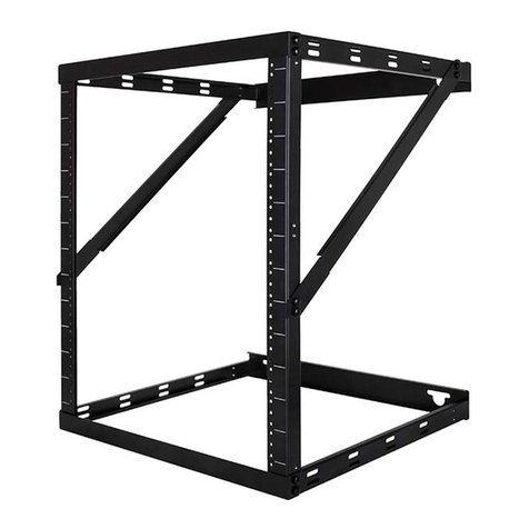
Wall-Mount Adjustable-Depth Patch Panel Rack
Package Contents
• 1 × Wall Mount Patch Panel Rack
• 1 × Mounting Template
• 5 × 8×63mm Lag Bolts (A)
• 5 × 8.4×19×2mm Lag Bolt Washers (B)
• 44 × #10-32 Screw with Washers (C)
• 4 × Hook and Loop Strips (D)
• 5 × Concrete Anchors (E)
SR-WM-PPH-4U-6-15
Maximum Weight
Capacity: 35lbs
SR-WM-PPH-8U-6-15
Maximum Weight
Capacity: 35lbs
Package Contents
• 1 × Wall Mount Patch Panel Rack
• 1 × Mounting Template
• 5 × 8×63mm Lag Bolts (A)
• 5 × 8.4×19×2mm Lag Bolt Washers (B)
• 28 × #10-32 Screw with Washers (C)
• 4 × Hook and Loop Strips (D)
• 5 × Concrete Anchors (E)
• 8 × #10-32 Flange Nuts
Package Contents
• 1 × Wall Mount Patch Panel Rack
• 1 × Mounting Template
• 5 × 8×63mm Lag Bolts (A)
• 5 × 8.4×19×2mm Lag Bolt Washers (B)
• 44 × #10-32 Screw with Washers (8 preinstalled) (C)
• 4 × Hook and Loop Strips (D)
• 5 × Concrete Anchors (E)
• 8 × #10-32 Flange Nuts
Tools Required for Installation
• Power Drill
• 3/32" drill bit
• Phillips screwdriver
• 1/2" (13mm) wrench
• level
• stud finder
SR-WM-PPH-2U-6
Maximum Weight
Capacity: 35lbs
2
Mounting
This product is designed to mount on a wood or sheetrock wall. Maximum Weight Capacity: 35lbs
1. Locate the studs in the wall to be used for mounting.
2. Place the cutout template in the desired position. Ensure it is level.
3. Drill pilot holes for your lag bolts (A) using a 3/32" drill bit. If desired, use a drywall saw to
remove the cable access cutout.
4. Screw the lag bolts (A) with washers (B) into the wall until roughly 1/4" of the bolt is still exposed.
With the 4U and 8U models, these bolts go into the lower position.
5. Swing the wings of the mount out to 90°. Adjust each brace arm so the hole in its end aligns
with the hole in the wing. Insert a rack screw with washer (C) through each arm and into the
wing and tighten. See above.
6. Hang the rack on the lag bolts (A). Ensure the washers (B) are between the rack and the lag
bolts (A). See below left.
7. Position the rack to the left or right until you reach your desired alignment. Tighten the lag bolts
(A). Add two more lag bolts (A) with washers (B) at the bottom. See above right.
3
Adjustment
The 4U and 8U models are equipped with extendable sides. These can be adjusted in or out to hold
needed equipment or to minimize the space the rack occupies.
The mount comes with two screws installed on each of the sides. Remove these to extend the arms.
When extending the sides, best practice is to extend the middle section first, and the final section last.
This gives you the strongest support.
Use the provided #10-32 rack screws
to mount your equipment.
Once the equipment is mounted and
the wiring connected, you can the
arms to minimize the space required.
Use provided hook and loop strips as
needed for cable management.
Extend this section first. Retract this
section last.
Extend this section second. Retract
this section first.
Once the sides are at their final
length, insert eight screws with
washers into each side, using the
holes shown at right.
Tighten the screws firmly to hold
the rack sides in place.
{
{
4
Technical Support
For chat and telephone, visit https://tech.control4.com/s/contactsupport • Email: T[email protected]
Visit tech.control4.com/technician for discussions, instructional videos, news, and more.
Warranty and Legal Notices
Find details of the product’s Limited Warranty at snapone.com/legal/ or request a paper copy from Customer Service at
866.424.4489. Find other legal resources, such as regulatory notices and patent and safety information, at snapone.com/legal/.
Copyright ©2021, Snap One, LLC. All rights reserved. Snap One and its respective logos are registered trademarks or
trademarks of Snap One, LLC (formerly known as Wirepath Home Systems, LLC), in the United States and/or other countries.
Control4 and Strong are also registered trademarks or trademarks of Snap One, LLC. Other names and brands may be
claimed as the property of their respective owners. Snap One makes no claim that the information contained herein covers all
installation scenarios and contingencies, or product use risks. Information within this specification subject to change without
notice.
220118-0940
Part # 200-SR-WM-003-C
Dimensions
7.539"
191.5mm
3.657"
92.9mm
19.606" / 498mm
MAX: 15" / 381.8mm
MIN: 6" / 152.4mm
14.587"
370.5mm
19.606" / 498mm
16" / 406.4mm
6" / 152.4mm
8U
4U
2U
MAX: 15" / 381.8mm
MIN: 6" / 152.4mm

Other Strong Rack & Stand manuals

Strong Carbon Series User manual

Strong

Strong Carbon Series User manual

Strong SM-FLAT-S User manual

Strong

Strong SM-FLAT-S User manual

Strong Strong Razor Series User manual

Strong

Strong Strong Razor Series User manual

Strong SR-CAB-8U User manual

Strong

Strong SR-CAB-8U User manual

Strong Contractor Series User manual

Strong

Strong Contractor Series User manual

Strong Strong VersaMount SM-VM-ART2-IW-XL User manual

Strong

Strong Strong VersaMount SM-VM-ART2-IW-XL User manual

Strong SM-CEILING-T-L User manual

Strong

Strong SM-CEILING-T-L User manual

Strong SM-PAD-LIFE User manual

Strong

Strong SM-PAD-LIFE User manual

Strong SR-CUSTOM Series User manual

Strong

Strong SR-CUSTOM Series User manual

Strong SR-CUSTOM Series User manual

Strong

Strong SR-CUSTOM Series User manual

Strong SM-CB-F-L User manual

Strong

Strong SM-CB-F-L User manual

Strong VersaBox SM-RBX-PRO-20-BLK User manual

Strong

Strong VersaBox SM-RBX-PRO-20-BLK User manual

Strong SM-CBP Series User manual

Strong

Strong SM-CBP Series User manual

Strong Strong Razor Series User manual
Strong

Strong Strong Razor Series User manual

Strong SR-WM-SK-19 User manual

Strong

Strong SR-WM-SK-19 User manual

Strong SR-WM-10U User manual

Strong

Strong SR-WM-10U User manual

Strong Strong Razor Series User manual

Strong

Strong Strong Razor Series User manual

Strong FS Series Operational manual

Strong

Strong FS Series Operational manual

Strong Strong Razor Series User manual

Strong

Strong Strong Razor Series User manual

Strong VersaBox SM-RBX-PRO-14-BLK User manual

Strong

Strong VersaBox SM-RBX-PRO-14-BLK User manual

Strong SR-WMS Series User manual

Strong

Strong SR-WMS Series User manual

Popular Rack & Stand manuals by other brands

Ergotron WorkFit-A Assembly instructions

Ergotron

Ergotron WorkFit-A Assembly instructions

Sunforce Unirac 33805 manual 

Sunforce

Sunforce Unirac 33805 manual 

Stealth Products TWBM480-TAB owner's manual

Stealth Products

Stealth Products TWBM480-TAB owner's manual

Unicol AVECTA TWIN SCREEN ACHP manual

Unicol

Unicol AVECTA TWIN SCREEN ACHP manual

peerless-AV SMARTMOUNT XT STX645 manual

peerless-AV

peerless-AV SMARTMOUNT XT STX645 manual

EFB Elektronik GmbH 53719.1 installation instructions

EFB Elektronik GmbH

EFB Elektronik GmbH 53719.1 installation instructions

Premier Mounts USA installation manual

Premier Mounts

Premier Mounts USA installation manual

Yamaha YPS200 owner's manual

Yamaha

Yamaha YPS200 owner's manual

ricoo TS3311 quick start guide

ricoo

ricoo TS3311 quick start guide

LG FS21GB manual

LG

LG FS21GB manual

CONTINENTAL EDISON TVB400 Mounting instructions

CONTINENTAL EDISON

CONTINENTAL EDISON TVB400 Mounting instructions

Ballucci FLR17.18 instruction manual

Ballucci

Ballucci FLR17.18 instruction manual

StarTech.com WALLSTSI2 user manual

StarTech.com

StarTech.com WALLSTSI2 user manual

Konig & Meyer 24100 quick start guide

Konig & Meyer

Konig & Meyer 24100 quick start guide

Ameriwood HOME 1781096PCOM Instruction booklet

Ameriwood HOME

Ameriwood HOME 1781096PCOM Instruction booklet

ONKRON TS1220 user guide

ONKRON

ONKRON TS1220 user guide

on stage SMS6600 manual

on stage

on stage SMS6600 manual

Hanwha Techwin SBV-136B manual

Hanwha Techwin

Hanwha Techwin SBV-136B manual

manuals.online logo
manuals.online logoBrands
  • About & Mission
  • Contact us
  • Privacy Policy
  • Terms and Conditions

Copyright 2025 Manuals.Online. All Rights Reserved.