STRS Energy BatteryProgBrain User manual

What is the “Battery Prog Brain” (BPB)
Battery Prog
Using unique micro-electronic technology it continually monitors the
battery power. When Battery Prog Brain detects power falling below the
threshold level required to start your engine, it automatically isolates the
battery from the electrical system. This will ensure the battery always have
enough power to start your engine and will prolong the battery life. There
are a few ways to reset the power according to the type of BPB you have
purchase.
*T3 & T4 have the ability to disconnect the battery from the electrical
system intentionally and to act as an anti-theft device.
*T4RV (Utility) is designed to extend battery life by protecting
utility/house/coach batteries rather than the vehicle starting battery and
can disconnect the battery from the electrical system intentionally to
preserve battery power when not in use.
Brain is an innovative accessory that easilyinstalls to any battery.
Updates to installation instructions will be posted on
www.batteryprogbrain.com
5
1
2
3
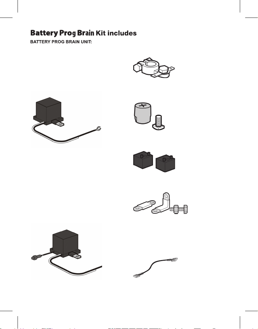
1. Positive (+) side of Battery Prog Brain (the printed
side) with Butterfly Connector
2. Black Ground Wire, attached to unit
3. White Antenna Wire, attached to unit (for Type
T2 & T3)
T4
instead of a remote control, to change the
position of the Battery Prog Brain (power
connected/disconnected) press the push button.
The button can be mounted/concealed
anywhere in the vehicle and is connected to the
Battery Prog Brain unit via a wire with a
connector.
T4RV looks like the T4 model but is
designed to be connected to the
utility/house/coach batteries in order to avoid
deep discharge which can prematurely end a
batteries life.
Mount the push button in the desired
location by tightening the nut provided
on the push button.
Uses a push button(5)
Aluminum Female Positive Post with Butterfly
Connector with Bolt and Lock Washer
Aluminum Male Positive Post with Bolt
and Lock Washer
Chassis Mounting Blocks
To distance the connection from the Chassis
L-Bracket & Straight Mounting Brackets
To help fit the BPB on the battery
Bypass Wire
To be used to bypass all the BPB functions
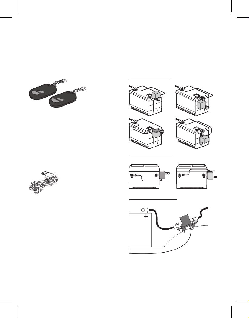
Remote Control to connect/disconnect the
power remotely
(T2 & T3 Models Only)
Remote Control Frequency: TX433.92 Mhz
Battery Type: 12 V 27 A (The batteries are
already installed)
Red Accessory Bypass Wire with Fuse Holder
To be used when there is a need to bypass the
BPB for an electrical consumer to stay active
at all times
Installation Instructions
NOTE: Battery location and position differ in
vehicles. With the supplied accessories you can
mount the Battery Prog Brain on the vehicle using
the Top Mount, Side Mount or Chassis Mount
positions.
Sample Configuration Options
Top Mounting Options
Side Mounting Options
Chassis Mounting Option
Red wire is to be used as the Accessory bypass
wire or the Engine ON wire(Required if ERD
function is not "ON").
If used as accessory bypass you can bypass a
particular circuit and allow power to it.
If used as ENGINE ON wire this will ensure the
BPB will not disconnect the power when the main
vehicle ignition switch is "ON" (Engine running)
Remote Control to connect/disconnect the
power remotely
(T2 & T3 Models Only)
Remote Control Frequency: TX433.92 Mhz
Battery Type: 12 V 27 A (The batteries are
already installed)
Red Accessory Bypass Wire with Fuse Holder
To be used when there is a need to bypass the
BPB for an electrical consumer to stay active
at all times
Installation Instructions
NOTE: Battery location and position differ in
vehicles. With the supplied accessories you can
mount the Battery Prog Brain on the vehicle using
the Top Mount, Side Mount or Chassis Mount
positions.
Sample Configuration Options
Top Mounting Options
Side Mounting Options
Chassis Mounting Option
Prog Brain (with the side printed +) to the
positive post on the battery using the
provided side mount screw. Then screw
in the red positive battery cable to the
other side of the Battery Prog Brain.
Amperage for the bypassed accessory
must not exceed 7.5Amps.
A) Locate the fuse that provides power
only to the accessory that you wish to
have it active at all times.
B) Attach the exposed end of the red
bypass wire to the fuse or device you
wish to have active on the non active side
of the fuse. A fuse tap connection may be
required.
C) Carefully route the wire from the fuse
to the Battery Prog Brain. A fuse-tap or
wire-tap connection may be required.
D) Attach the connector end of the red
bypass wire onto the butterfly connector
on the female positive post of the Battery
Prog Brain.
required if ERD tested OK)
Installation of the Engine On wire will
prevent the Battery Prog Brain from discon-
necting the battery while the engine is
running. This will also prevent the Battery
voltage level drops below 11.8V as could
be the case with accessories that briefly
reduce the voltage below the threshold
level or in the case of problems with the
vehicle electrical components. i.e. bad
alternator.
This wire must be installed to ensure the
Battery Prog Brain will not disconnect the
power while the engine is running. (Not
required if ERD tested OK)
Optional: Red Accessory Bypass Wire
Installation
Installation of the red accessory bypass
wire will provide you with continuous 12V
power to an accessory or accessories
bypassing the Battery Prog Brain, designed to
allow you to save presets or memory
settings or any electrical device that is
required to stay active at all times.
STEP 4: STEP 5:
A) Locate a wire or fuse that has 12V
when the ignition switch is in the “ON” or
“RUN” position and is 0V when the
ignition switch is in the “OFF” position.
engine on wire onto the single connector
on the Battery Prog Brain that is labeled with
“ACC”.
C) Attach the other end of the supplied
or fuse as located in step A above. This
may require running a wire to the interior
of the vehicle. A fuse-tap or wire-tap
connection may be required.
Prog Brain from disconnecting the battery if the
Exact location of the fuse & fuse panel
will differ by manufacturer; consult your
owner’s manual or wiring schematic for
the vehicle to locate fuses for the
accessories.
NOTE:
Use of this feature will bypass the Battery
to drop below the minimum charge
needed to start your vehicle.
NOTE:
Prog Brain and may allow the battery voltage
Install Red Engine On Wire. (Not
red engine on wire to the selected wire
B) Slide the connector end of the red

If your vehicle has a multi-battery
configuration, Battery Prog Brain can be
mounted to any battery configuration.
However, any primary live positive battery
post must have its own Battery Brain.
Consult a certified technician if you
require assistance.
If the two or more batteries are
connected in Parallel, to one primary red
positive cable, then only one Battery Prog
Brain is required. Follow the installation
instructions as previously stated.
If two or more batteries are connected in
parallel, two primary red positive cables,
then you will require two Battery Prog Brains,
to ensure that the batteries are effectively
isolated from the electrical system once
the disconnection threshold is reached.
Mount both Battery Prog Brains at the primary
positive posts connected to the Starter,
Alternator, ECM or any accessory device
that requires electrical power.
Installation Tip: Remote Location: If you
wish to mount the Battery Prog Brain in a
remote location due to space limitations,
or if desired, use proper battery cable.
(Additional cable not supplied)
Series configuration options shown for
example purposes only.
MULTI BATTERY INSTALLATION
SAMPLE CONFIGURATION OPTIONS
Prog

Press the button of the RC or the push button
to establish connection Start the engine after
installation is complete. If the engine starts
properly proceed to the next step. If not, review
the installation instruction or consult a certified
technician.
The remote control unit supplied with Battery
supplied with the Battery Prog Brain T4 can be used
to disconnect and reconnect power by choice
(as an anti-theft device), as well as reestablish-
ing power after the BPB has disconnected the
power. Press and hold for 4 consecutive seconds
either the remote control button or mounted
switch to disconnect, To reconnect or reestablish
power to electrical accessories and to start the
engine press the button once.
Turn the engine off and turn on as
many electrical accessories (i.e. lights, radio,
and wind shield wipers) as possible and leave
them on. The Battery Prog Brain will cut power from
the battery automatically – confirming the
Battery Prog Brain is working. This may take some
time, depending on the battery’s age and state
of charge.
C) TO TEST THE REMOTE CONTROL UNIT /
WIRED REMOTE BUTTON UNIT(BATTERY
III & IV):
Prog Brain T3 and the wired remote button
Start the engine, press the remote control/push
button and hold for 10 seconds
works OK, if the power has disconnected
You need to connect the “engine on” wire.
D) TO TEST THE ERD FUNCTION.
Battery Prog Brain
BATTERY PROG BRAIN
PROG BRAIN
If the power has not disconnected the ERD
The ERD does not detect the electronic noise
y
3. Check that the black ground wire is securely
attached to the negative (-) post on the batter .
3. Check that the black ground wire is securely
attached to the negative (-) post on the battery.
1. Be sure your battery is holding the proper
charge.
2. Make sure the positive side of the Battery
Prog Brain (the printed side) is attached to the
positive (+) post of the battery. If a warning light for NO CHARGE or BATTERY
WARNING illuminates on your dashboard, stop
your vehicle at a safe area and disconnect the
Engine-On wire from the ACC connector and
connect the bypass wire from the butterfly
connector to the ACC
With the power left in your battery approach a
technician to take care of the no charge problem,
otherwise you will get stranded with a completely
dead battery and the vehicle might shut off while
you are on the road.
1. Consult a certified technician.
1. Make sure that the light on the Remote
Control is lit when you press the button
down. If the light does not come on, open the
Remote Control and replace
the battery.
2. Hold the Remote Control button down for five
seconds disconnect the power and one press to
activate the power
1. Your car battery may be low in power due to
Alternator function.
If it cannot hold a charge, it may be at the end
of its life cycle.
2. The electrical system might have an
unknown short. Consult a certified technician.
3. Make sure all lights are off.
4. Disconnect all accessory electronics (radio,
phone charger, DVD player, etc.) and check
again.
AFTER INSTALLATION, THE BATTERY
BRAIN DOESN’T SEEM TO
BE WORKING.
AFTER THE BATTERY PROG BRAIN HAS
DISCONNECTED POWER,
THE REMOTE CONTROL DOES NOT RESET
THE POWER.
BATTERY PROG BRAIN IS FREQUENTLY
DISCONNECTING POWER FOR
NO APPARENT REASON.
YOU CANNOT DETERMINE A BATTERY
PROG BRAIN INSTALLATION CONFIGURATION
FOR YOUR VEHICLE OR LOCATE BATTERY
CONNECTIONS.
WHAT TO DO
WHAT TO DO
IMPORTANT NOTE:
WHAT TO DO
WHAT TO DO
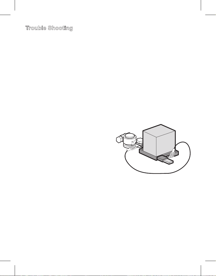
Trouble Shooting
PROG
Bypass Wire
ACC
ACC
The Bypass wire when connected as shown in the
picture will reconnect the power and will keep the
power connected as long as the wire is connected
from the plus side to the ACC.
Note: This wire connection can be used to
reconnect the power in case the remote control
(T3) is lost or if there is a problem with the push
button (T4).
After the BPB has reconnected the power
disconnect the wire to ensure full function of the
unit.

Your Battery Prog Brain™ is covered by a conditional, limited warranty to the original purchaser.
This unit is guaranteed to the original retail purchaser against defects in quality or workmanship for
a period of two years from the date of original purchase. If this unit fails because of a manufacturing
defect within 30 days of purchase, return the unit, with your receipt, to the retailer. After 30 days of
purchase, but within the warranty period, if the unit was purchased within the continental United
States, return it, freight prepaid, to STRSEnergy Inc. for repair or replacement. If the unit was purchased
outside the continental United States, return the unit to the place of purchase.
This warranty does not cover damage due to operation other than the use of the correct Battery Prog
Brain model on the specified battery voltage. This warranty does not extend to any defect, malfunction,or
failure caused by accidents, misuse, abuse, improper installation (including disassembly of Battery
Prog Brain, use of the product with equipment for which it was not intended, or unauthorized alterations or
repairs.
All implied warranties are hereby limited in duration to the period of two years from the date of original
retail purchase. Incidental or consequential damages arising from a breach of either express or
implied warranties are hereby disclaimed and excluded.
Some states do not allow the exclusion of limitation of incidental or consequential damages, so this
limitation or exclusion may not apply to you.
Neither STRSEnergy, Inc. nor retailers selling Battery Prog Brain are responsible for indirect, incidental,
special, punitive or consequential damages arising from improper installation, the use of or inability to
use BatteryProg Brain. Except for this limited warranty, STRSEnergy, Inc. has not made,and specifically
disclaims any warranty or representation of any kind, express or implied, direct or indirect, of product
fitness for a particular purpose.
Made in China
Made in Israel
Made in U.S.A
Limited Warranty
BATTERY SAFETY WARNING!
When working with lead acid batteries and accessories, caution must be employed:
• Shield eyes. Do not open vent caps or puncture battery casing in any way.
• Sulfuric acid can cause blindness and severe burns.
• Rinse hands and flush eyes with water immediately.
•Avoid sparks, flames and smoking.
PROPOSITION 65 WARNING
Battery posts, terminals, and related accessories contain lead and lead compounds. Chemicals known
to the State of California to cause cancer and reproductive harm. Wash hands after handling.
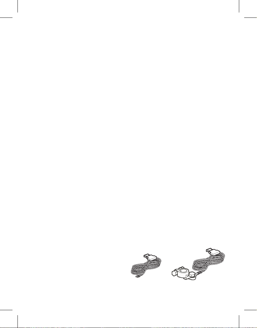
The BPB Programmer has
the following parts:
The BPB Programmer has the following parts:
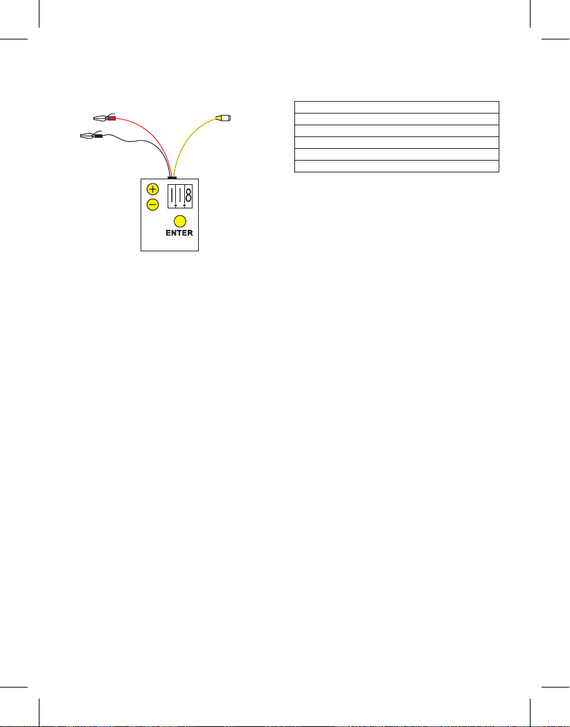
The box and on it the three digits display, a plus
and minus and the ENTER buttons.
The three wires, Black, Red and Yellow.
1 When connecting the Black wire to the
negative side of a battery and the Red to the
positive, the Programmer is a Volt meter that will
display the actual voltage of the battery, when it
is connected to the battery and you start the
engine it will display how low the battery voltage
went at the starting point by pressing the “+”
button or it will display the rate of charge by
pressing “-“button.
That gives the user a very important diagnostic
tool to test the battery condition and alternator
condition.
A battery of 12V suppose to have at list 12.6V in
normal condition, when starting the engine
battery voltage should not drop under 8.5V
A good state of charge (alternator) should be
at 13V.
2. When connecting the yellow wire to the ACC
connector on the BPB (Battery Programmable
Brain) and pressing the remote control or the
push button 5 times
The display will start blinking, that means the
programmer is communicating with the BPB
unit, the blinking display will show the
disconnecting point the BPB is programmed to
disconnect at, by pressing the (“+”) button this
number will change upward, by pressing the
(“-“) button it will change the numbers
downward, when you got to the desired point
press the ENTER button and this number will be
implemented into the BPB and the next screen
of Delay time will appear blinking, repeat the
same steps as for the voltage until you riches the
desire delay time and press ENTER.
The next display will show the ERD (Engine
running detection) AS ER0 or ER1 while blinking
if you want the ERD to be “ON” then you chose
the ER1 by pressing the (“+”) button if you want
it off then press the minus button, when the
display shows the ERD as you want it then press
ENTER.
This time you will have the reconnect function
blinking scroll up or down until you get the
reconnect point that you want OR if you want it
on OFF then press the (“+”) button until it will
show OFF then press the ENTER button and
disconnect the wires Black Red and Yellow, the
order dose not matter.
Barrery condition
Very good
Good
Fair
Poor
Bad
Voltage at engine start
9V and higher
8.5V to 9V
8V to 8.5V
7.5V to 8V
7V to 7.5V
BPB Programmer Users
Manual
What does the Programmer
do?

Headquarter:
28 Osprey Rd.Key Largo, Florida 33037 USA
Marketing & Sales:
8-04 Arnot Place
Fair Lawn NJ 07410 USA
Tel:201-968-7042
Fax:201-548-5252
Technical Support: 201-968-7042
R&D and Manufacturing:
83 Nahal Soreq
Moshav Tal Shahar 76805
Israel
Tel:972-52-2654492
Fax:972-72-2510026
For more information and other products go to
www.batteryprogbrain.com
Version: 2012 06A
Table of contents
Popular Automobile Accessories manuals by other brands


Tessera4x4
Tessera4x4 SOT-ROLL Series installation manual

Rago FABRICATION
Rago FABRICATION R2200TTUNBCM installation guide

GMC
GMC IL-GM3 Quick start installation guide

Dension
Dension WiRC user manual

DV8 OFFROAD
DV8 OFFROAD CMJL-01 installation manual

Abrams
Abrams UG-600 Installation and configuration manual