Struers Unitom-2 User manual

Manual No.: 15377001
Date of Release ..20
Unitom-2
Instruction Manual

Unitom-2
Instruction Manual
Table of Contents Page
User’s Guide ............................................................... 1
Reference Guide ....................................................... 12
Quick Reference Guide ............................................ 25
A
lways state Serial No and Voltage/frequency if you have technical questions or when ordering spare parts.
You will find the Serial No. and Voltage on the type plate of the machine itself. We may also need the Date
and Article No of the manual. This information is found on the front cover.
The following restrictions should be observed, as violation of the restrictions may cause cancellation of
Struers legal obligations:
Instruction Manuals: Struers Instruction Manual may only be used in connection with Struers equipment
covered by the Instruction Manual.
Service Manuals: Struers Service Manual may only be used by a trained technician authorised by Struers.
The Service Manual may only be used in connection with Struers equipment covered by the Service Manual.
Struers assumes no responsibility for errors in the manual text/illustrations. The information in this manual is
subject to changes without notice. The manual may mention accessories or parts not included in the present
version of the equipment.
Original instructions. The contents of this manual is the property of Struers. Reproduction of any part of
this manual without the written permission of Struers is not allowed.
A
ll rights reserved. © Struers 2012.
Struers A/S
Pederstrupvej 84
DK-2750 Ballerup
Denmark
Telephone +45 44 600 800
Fax +45 44 600 801
Unitom-2
Instruction Manual
Unitom-2
Safety Precaution Sheet
To be read carefully
before use
1. The operator(s) should be fully instructed in the use of the machine and
its cut-off wheels according to the Instruction Manual and the
instructions for the cut-off wheels.
2. The machine must be placed on a safe and stable support table. All
safety functions and guards of the machine must be in working order.
3. Use only intact cut-off wheels. The cut-off wheels must be approved for
min. 50 m/s.
4. Observe the current safety regulations for handling, mixing, filling,
emptying and disposal of the additive for cooling fluid.
5. The workpiece must be securely fixed in the quick-clamping device or
the like. Large or sharp workpieces must be handled in a safe way.
6. The cutting handle should be lowered slowly and carefully, in order to
avoid breaking the cut-off wheel. The cutting handle automatically
returns to its top position when you let go the handle.
7. Struers recommends the use of exhaustion as the materials to be cut
may emit harmful gasses or dust.
8. Use of working gloves is recommended as workpieces may be both
very hot and produce sharp edges.
9. Use of safety shoes is recommended when handling large or heavy
workpieces.
10. Use of safety goggles is recommended when using the flushing hose.
The equipment should only be used for its intended purpose and as detailed in the Instruction Manual.
The equipment is designed for use with consumables supplied by Struers. If subjected to misuse, improper
installation, alteration, neglect, accident or improper repair, Struers will accept no responsibility for
damage(s) to the user or the equipment.
Dismantling of any part of the equipment, during service or repair, should always be performed by a qualified
technician (electromechanical, electronic, mechanical, pneumatic, etc.).


Unitom-2
Instruction Manual
1
User’s Guide
Table of Contents Page
1.Getting Started
Checking the Contents of Packing ..................................................... 2
Unpacking Unitom-2 ........................................................................... 2
Placing Unitom-2 ................................................................................ 2
Getting Acquainted with Unitom-2 ...................................................... 3
Noise Level ........................................................................................ 4
Supplying Power ................................................................................ 4
Direction of the Cut-off Wheel ................................................... 4
Connecting a Cooli Cooling Unit ........................................................ 5
2.Basic Operations
Using the Controls .............................................................................. 6
Front Panel Controls of Unitom-2 ............................................. 6
Front Panel Controls .......................................................................... 7
Cooling Valve Positions ............................................................ 8
Changing the Cut-off Wheel ............................................................... 9
Clamping the Workpiece .................................................................... 9
Starting/Stopping the Cutting Process ............................................. 10
Flushing the Cutting Chamber ......................................................... 11

Unitom-2
Instruction Manual
2
1. Getting Started
In the packing box you should find the following parts:
1 Fork spanner, 30 mm, for changing the cut-off wheel
1 Grease gun, for lubrication of tilting frame bearings
2 Cover plugs for threads for cutting tables
1 Drain angle, 450
1 Drain angle, 900
1 Outlet hose 2 m
for connection to external cooling unit
2 Hose clamps, 35-60 mm
1 Set of Instruction Manuals
Remove the wooden block holding the spindle using a 17 mm
spanner.
Insert the two cover plugs delivered with the machine in the
threaded holes.
Unitom-2 should be placed on the optional Struers Table Unit, or a
table which is able to carry a weight of min. 200 kg.
Adjust the table height using the screws in the table legs. It is
important that the table and Unitom-2 are level. Place Unitom-2 on
the table. If the machine is not horizontal, you must adjust the height
for each corner, as follows:
Loosen the upper 13 mm nut under the corner screw.
Adjust the lower 8 mm nut with a spanner.
Fasten the upper 13 mm nut again.
Repeat the adjustment for each of the other three corners until
Unitom-2 is levelled.
Checking the Contents
of Packing
Unpacking Unitom-2
Placing Unitom-2

Unitom-2
Instruction Manual
3
Take a moment to familiarise yourself with the location and names of
the Unitom-2 components.
Front panel controls
Cutting Table
Quick-clamping device
Table Unit (optional)
Recirculation cooling unit
Cutting handle
Side plate
Main switch
Protection guard with window
Cooling valve
Getting Acquainted
with Unitom-2

Unitom-2
Instruction Manual
4
Approx. 76 dB (A) measured at idle running, at a distance of
1.0 m/39.4” from the machine.
Unitom-2 is factory mounted with an electric cable. Mount a plug
on the cable according to the following:
50 hz 60 hz
Phase Black and brown
Earth Yellow/green
L1 Black
L2 Red
L3 Orange
Earth Green
Check that the cut-off wheel rotates in the direction indicated on the
label attached to the guard of Unitom-2. If the direction of rotation is
incorrect:
50 hz 60 hz
Switch two of the phases Switch phases L1 and L2
Noise Level
Supplying Power IMPORTANT
Check that the mains voltage corresponds to the voltage
stated on the type plate on the side of the machine.
Direction of the Cut-off Wheel

Unitom-2
Instruction Manual
5
To ensure optimal cooling, Unitom can be fitted with a Cooli unit. The
Cooling System 5 is a Cooli configuration designed for use with
Unitom.
To connect the Unitom to a cooling unit:
Plug the Cooli control unit’s communication cable into the
Unitom’s control socket.
Connect the quick coupling on the Unitom’s cooling fluid inlet
tube to the cooling unit’s pump outlet (A).
Insert the drain pipe in the water outlet on the back of
Unitom-2 and mount the 90° elbow pipe . Lubricate the sealing
ring with grease or soap to facilitate insertion. (Use the other
elbow pipe if more suitable).
Strip the steel spring from approx. 3 cm of the outlet hose and
cut. Bend the cut end towards the centre of the hose. Mount the
outlet hose onto the elbow pipe and clamp the stripped
section using a hose clamp.
Check that the outlet hose slopes downwards when connected. If
necessary adjust the length of the hose.
Insert the open end of the hose into mounting hole in the bracket
on top of the Cooli filter unit (B).
Connect the cooling unit to the mains power supply.
Connecting a Cooli
Cooling Unit
Note:
Cooling System 5 includes a static filter.
For intensive use, and for materials generating a lot of swarf,
a bandfilter is recommended.
Note
Before connecting the cooling unit to the Unitom,
follow the instructions in the Cooli Instruction Manual
to prepare it for use.
IMPORTANT
Before connecting, check that the mains voltage corresponds to the voltage
stated on the type plate on the side of the machine.
A
B
Unitom-2
Instruction Manual
6
2. Basic Operations
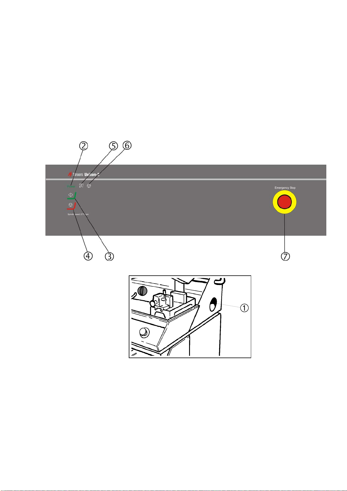
Using the Controls
Front Panel Controls of Unitom-2
Location of the Main Switch
Table of contents
Languages:
Other Struers Cut-off Machine manuals


