DeWalt DCS438 User manual

final page size: 8.5 x 5.5 infinal page size: 8.5 x 5.5 in
If you have questions or comments, contactus.
Pour toute question ou tout commentaire, nouscontacter.
Si tiene dudas o comentarios,contáctenos.
1‑800‑4‑DeWALT
DCS438
3" Cut Off Tool
Outil de coupe de 3po
Herramienta de corte de 3"
Instruction Manual
Guide D’utilisation
Manual de instrucciones

1
Fig. A
Components
1 Battery
2 Battery release button
3 Handle
4 Trigger
5 Forward/reverse/lock off button
6 Spindle lock button
7 Direction indicator
8 Dust extraction port (AirLockTM)
9 Dust shroud with adjustable shoe
10 Depth of cut gauge
11 Depth of cut wing nut
12 Guard
13 Hex wrench
14 Lanyard readyTM mounting hole
2
1
14
3
13
8
10
11
7
9
6
5
4
Composants
1 Pile
2 Bouton de libération de la pile
3 Poignée
4 Gâchette
5 Bouton Avance/recul/verrouillage
6 Bouton de verrouillage de la tige
7 Indicateur de direction
8 Port d’extraction de la poussière
(AirLockMC)
9 Capteur de poussière avec sabot
réglable
10 Jauge de profondeur de coupe
11 Profondeur de l’écrou papillon de
coupe
12 Protection
13 Clé hexagonale
14 Trou de montage Lanyard readyMC
Componentes
1 Batería
2 Botón de liberación de batería
3 Manija
4 Gatillo
5 Botón de bloqueo de apagado/
avance/reversa
6 Botón de bloqueo de husillo
7 Indicador de dirección
8 Puerto de extracción de polvo
(AirLockTM)
9 Aro de refuerzo de polvo con
zapata ajustable
10 Profundidad de calibrador de corte
11 Profundidad de tuerca de mariposa
de corte
12 Protección
13 Llave hexagonal
14 Orificio de montaje Lanyard readyTM

2
Fig.B Fig.C
Fig.D Fig.E
Fig.F Fig.G
75–100% charged
Chargé de 75 à 100 %
75–100% cargada
51–74% charged
Chargé de 51 à 74 %
51–74% cargada
< 50% charged
Chargé de < 50 %
< 50% cargada
Pack needs to be charged
Le bloc‑piles doit être rechargé
La batería tiene que cargarse
Indicators/Témoin/Indicador
Charging
Bloc‑piles en Cours
de Chargement
Unidad en Proceso de Carga
Fully Charged
Bloc‑piles Chargé
Unidad Cargada
Hot/Cold Pack Delay
Suspension de Charge Contre
le Chaud/Froid
Restraso por Unidad Caliente/
Fría
8
23
24 24
23
12
13
19
18
20
16
15
17
12
9
11
22
21

3
Fig.H Fig.I
Fig.J Fig.K
2
1
3
6
25
27
26
29

ENGLISH
4
2) Electrical Safety
a ) Power tool plugs must match the outlet. Never
modify the plug in any way. Do not use any
adapter plugs with earthed (grounded) power
tools. Unmodified plugs and matching outlets will
reduce risk of electricshock.
b ) Avoid body contact with earthed or grounded
surfaces, such as pipes, radiators, ranges and
refrigerators. There is an increased risk of electric
shock if your body is earthed orgrounded.
c ) Do not expose power tools to rain or wet
conditions. Water entering a power tool will increase
the risk of electricshock.
d ) Do not abuse the cord. Never use the cord for
carrying, pulling or unplugging the power tool.
Keep cord away from heat, oil, sharp edges or
moving parts. Damaged or entangled cords increase
the risk of electricshock.
e ) When operating a power tool outdoors, use an
extension cord suitable for outdoor use. Use of
a cord suitable for outdoor use reduces the risk of
electricshock.
f ) If operating a power tool in a damp location
is unavoidable, use a ground fault circuit
interrupter (GFCI) protected supply. Use of a GFCI
reduces the risk of electricshock.
3) Personal Safety
a ) Stay alert, watch what you are doing and use
common sense when operating a power tool. Do
not use a power tool while you are tired or under
the influence of drugs, alcohol or medication. A
moment of inattention while operating power tools
may result in serious personalinjury.
b ) Use personal protective equipment. Always wear
eye protection. Protective equipment such as a dust
mask, non‑skid safety shoes, hard hat, or hearing
protection used for appropriate conditions will reduce
personalinjuries.
c ) Prevent unintentional starting. Ensure the switch
is in the off‑position before connecting to power
source and/or battery pack, picking up or carrying
the tool. Carrying power tools with your finger on the
switch or energizing power tools that have the switch
on invitesaccidents.
d ) Remove any adjusting key or wrench before
turning the power tool on. A wrench or a key left
attached to a rotating part of the power tool may result
in personalinjury.
e ) Do not overreach. Keep proper footing and
balance at all times. This enables better control of the
power tool in unexpectedsituations.
f ) Dress properly. Do not wear loose clothing or
jewelry. Keep your hair, clothing and gloves away
from moving parts. Loose clothes, jewelry or long
hair can be caught in movingparts.
g ) If devices are provided for the connection of dust
extraction and collection facilities, ensure these
are connected and properly used. Use of dust
collection can reduce dust‑relatedhazards.
GENERAL POWER TOOL SAFETY WARNINGS
WARNING: Read all safety warnings, instructions,
illustrations and specifications provided with
this power tool. Failure to follow all instructions
listed below may result in electric shock, fire and/or
seriousinjury.
SAVE ALL WARNINGS AND INSTRUCTIONS FOR
FUTUREREFERENCE.
The term “power tool” in the warnings refers to your
mains‑operated (corded) power tool or battery‑operated
(cordless) powertool.
1) Work Area Safety
a ) Keep work area clean and well lit. Cluttered or dark
areas inviteaccidents.
b ) Do not operate power tools in explosive
atmospheres, such as in the presence of
flammable liquids, gases or dust. Power tools create
sparks which may ignite the dust orfumes.
c ) Keep children and bystanders away while
operating a power tool. Distractions can cause you
to losecontrol.
Definitions: Safety Alert Symbols and Words
This instruction manual uses the following safety alert
symbols and words to alert you to hazardous situations and
your risk of personal injury or propertydamage.
DANGER: Indicates an imminently hazardous
situation which, if not avoided, will result in death or
seriousinjury.
WARNING: Indicates a potentially hazardous situation
which, if not avoided, could result in death or
seriousinjury.
CAUTION: Indicates a potentially hazardous situation
which, if not avoided, may result in minor or
moderateinjury.
(Used without word) Indicates a safety
relatedmessage.
NOTICE: Indicates a practice not related to
personal injury which, if not avoided, may result in
propertydamage.
Intended Use
Your cut‑off tool is designed for professional
cuttingapplications.
DO NOT use in the presence of flammable liquids orgases.
Your cut‑off tool is a professional powertool.
DO NOT let children come into contact with the tool.
Supervision is required when inexperienced operators use
thistool.
English (original instructions)
WARNING: Read all safety warnings and all
instructions. Failure to follow the warnings and
instructions may result in electric shock, fire and/or
seriousinjury.
WARNING: To reduce the risk of injury, read the
instructionmanual.

5
ENGLISH
CUT‑OFF MACHINE SAFETY WARNINGS
a ) The guard provided with the tool must be securely
attached to the power tool and positioned for
maximum safety, so the least amount of wheel is
exposed towards the operator. Position yourself
and bystanders away from the plane of the
rotating wheel. The guard helps to protect operator
from broken wheel fragments and accidental contact
withwheel.
b ) Use only bonded reinforced or diamond cut‑off
wheels for your power tool. Just because an
accessory can be attached to your power tool, it does
not assure safeoperation.
c ) The rated speed of the accessory must be at least
equal to the maximum speed marked on the
power tool. Accessories running faster than their rated
speed can break and flyapart.
d ) Wheels must be used only for recommended
applications. For example: do not grind with the
side of cut‑off wheel. Abrasive cut‑off wheels are
intended for peripheral grinding, side forces applied to
these wheels may cause them toshatter.
e ) Always use undamaged wheel flanges that are of
correct diameter for your selected wheel. Proper
wheel flanges support the wheel thus reducing the
possibility of wheelbreakage.
f ) Do not use worn down reinforced wheels from
larger power tools. Wheels intended for a larger
d ) Under abusive conditions, liquid may be ejected
from the battery; avoid contact. If contact
accidentally occurs, flush with water. If liquid
contacts eyes, additionally seek medical help.
Liquid ejected from the battery may cause irritation
orburns.
e ) Do not use a battery pack or tool that is damaged
or modified. Damaged or modified batteries may
exhibit unpredictable behavior resulting in fire,
explosion or risk ofinjury.
f ) Do not expose a battery pack or tool to
fire or excessive temperature. Exposure to
fire or temperature above 265°F (130°C) may
causeexplosion.
g ) Follow all charging instructions and do not
charge the battery pack or tool outside the
temperature range specified in the instructions.
Charging improperly or at temperatures outside the
specified range may damage the battery and increase
the risk offire.
6) Service
a ) Have your power tool serviced by a qualified
repair person using only identical replacement
parts. This will ensure that the safety of the power tool
ismaintained.
b ) Never service damaged battery packs. Service
of battery packs should only be performed by the
manufacturer or authorized serviceproviders.
h ) Do not let familiarity gained from frequent use of
tools allow you to become complacent and ignore
tool safety principles. A careless action can cause
severe injury within a fraction of asecond.
4) Power Tool Use and Care
a ) Do not force the power tool. Use the correct power
tool for your application. The correct power tool
will do the job better and safer at the rate for which it
wasdesigned.
b ) Do not use the power tool if the switch does not
turn it on and off. Any power tool that cannot be
controlled with the switch is dangerous and must
berepaired.
c ) Disconnect the plug from the power source and/
or remove the battery pack, if detachable, from
the power tool before making any adjustments,
changing accessories, or storing power tools. Such
preventive safety measures reduce the risk of starting
the power toolaccidentally.
d ) Store idle power tools out of the reach of children
and do not allow persons unfamiliar with the
power tool or these instructions to operate the
power tool. Power tools are dangerous in the hands of
untrainedusers.
e ) Maintain power tools and accessories. Check
for misalignment or binding of moving parts,
breakage of parts and any other condition
that may affect the power tool’s operation. If
damaged, have the power tool repaired before
use. Many accidents are caused by poorly maintained
powertools.
f ) Keep cutting tools sharp and clean. Properly
maintained cutting tools with sharp cutting edges are
less likely to bind and are easier tocontrol.
g ) Use the power tool, accessories and tool bits etc.
in accordance with these instructions, taking
into account the working conditions and the
work to be performed. Use of the power tool for
operations different from those intended could result in
a hazardoussituation.
h ) Keep handles and grasping surfaces dry, clean
and free from oil and grease. Slippery handles and
grasping surfaces do not allow for safe handling and
control of the tool in unexpectedsituations.
5) Battery Tool Use and Care
a ) Recharge only with the charger specified by the
manufacturer. A charger that is suitable for one type
of battery pack may create a risk of fire when used with
another batterypack.
b ) Use power tools only with specifically designated
battery packs. Use of any other battery packs may
create a risk of injury andfire.
c ) When battery pack is not in use, keep it away
from other metal objects, like paper clips, coins,
keys, nails, screws or other small metal objects,
that can make a connection from one terminal to
another. Shorting the battery terminals together may
cause burns or afire.

ENGLISH
6
q ) Do not use accessories that require liquid
coolants. Using water or other liquid coolants may
result in electrocution orshock.
FURTHER SAFETY INSTRUCTIONS FOR
ABRASIVE CUTTING‑OFF OPERATIONS
Kickback and Related Warnings
Kickback is a sudden reaction to a pinched or snagged rotating
wheel, backing pad, brush or any other accessory. Pinching or
snagging causes rapid stalling of the rotating accessory which
in turn causes the uncontrolled power tool to be forced in the
direction opposite of the accessory’s rotation at the point of
thebinding.
For example, if an abrasive wheel is snagged or pinched by the
workpiece, the edge of the wheel that is entering into the pinch
point can dig into the surface of the material causing the wheel
to climb out or kick out. The wheel may either jump toward or
away from the operator, depending on direction of the wheel’s
movement at the point of pinching. Abrasive wheels may also
break under theseconditions.
Kickback is the result of power tool misuse and/or incorrect
operating procedures or conditions and can be avoided by
taking proper precautions as given below:
a ) Maintain a firm grip on the power tool and
position your body and arm to allow you to resist
kickback forces. Always use auxiliary handle, if
provided, for maximum control over kickback or
torque reaction during start‑up. The operator can
control torque reaction or kickback forces, if proper
precautions aretaken.
b ) Never place your hand near the rotating
accessory. Accessory may kickback over yourhand.
c ) Do not position your body in line with the
rotating wheel. Kickback will propel the tool in
direction opposite to the wheel’s movement at the
point ofsnagging.
d ) Use special care when working corners, sharp
edges etc. Avoid bouncing and snagging the
accessory. Corners, sharp edges or bouncing have a
tendency to snag the rotating accessory and cause loss
of control orkickback.
e ) Do not attach a saw chain, woodcarving blade,
segmented diamond wheel with a peripheral gap
greater than 10mm or toothed saw blade. Such
blades create frequent kickback and loss ofcontrol.
f ) Do not “jam” the wheel or apply excessive
pressure. Do not attempt to make an excessive
depth of cut. Overstressing the wheel increases the
loading and susceptibility to twisting or binding of
the wheel in the cut and the possibility of kickback or
wheelbreakage.
g ) When wheel is binding or when interrupting a cut
for any reason, switch off the power tool and hold
the power tool motionless until the wheel comes
to a complete stop. Never attempt to remove
the wheel from the cut while the wheel is in
power tool are not suitable for the higher speed of a
smaller tool and mayburst.
g ) The outside diameter and the thickness of your
accessory must be within the capacity rating of
your power tool. Incorrectly sized accessories cannot
be adequately guarded orcontrolled.
h ) The arbour size of wheels and flanges must
properly fit the spindle of the power tool. Wheels
and flanges with arbour holes that do not match the
mounting hardware of the power tool will run out
of balance, vibrate excessively and may cause loss
ofcontrol.
i ) Do not use damaged wheels. Before each use,
inspect the wheels for chips and cracks. If power
tool or wheel is dropped, inspect for damage or
install an undamaged wheel. After inspecting
and installing the wheel, position yourself and
bystanders away from the plane of the rotating
wheel and run the power tool at maximum no
load speed for one minute. Damaged wheels will
normally break apart during this testtime.
j ) Wear personal protective equipment. Depending
on application, use face shield, safety goggles
or safety glasses. As appropriate, wear dust
mask, hearing protectors, gloves and shop apron
capable of stopping small abrasive or workpiece
fragments. The eye protection must be capable of
stopping flying debris generated by various operations.
The dust mask or respirator must be capable of
filtering particles generated by your operation.
Prolonged exposure to high intensity noise may cause
hearingloss.
k ) Keep bystanders a safe distance away from
work area. Anyone entering the work area must
wear personal protective equipment. Fragments
of workpiece or of a broken wheel may fly away and
cause injury beyond immediate area ofoperation.
l ) Hold the power tool by insulated gripping
surfaces only, when performing an operation
where the cutting accessory may contact hidden
wiring. Cutting accessory contacting a "live" wire may
make exposed metal parts of the power tool "live" and
could give the operator an electricshock.
m ) Never lay the power tool down until the accessory
has come to a complete stop. The spinning wheel
may grab the surface and pull the power tool out of
yourcontrol.
n ) Do not run the power tool while carrying it at your
side. Accidental contact with the spinning accessory
could snag your clothing, pulling the accessory into
yourbody.
o ) Regularly clean the power tool’s air vents. The
motor’s fan will draw the dust inside the housing and
excessive accumulation of powdered metal may cause
electricalhazards.
p ) Do not operate the power tool near flammable
materials. Sparks could ignite thesematerials.

7
ENGLISH
Additional Safety Information
WARNING: Never modify the power tool or any part of
it. Damage or personal injury couldresult.
WARNING: ALWAYS use safety glasses. Everyday
eyeglasses are NOT safety glasses. Also use face or
dust mask if cutting operation is dusty. ALWAYS WEAR
CERTIFIED SAFETYEQUIPMENT:
• ANSI Z87.1 eye protection (CAN/CSA Z94.3),
• ANSI S12.6 (S3.19) hearing protection,
• NIOSH/OSHA/MSHA respiratoryprotection.
WARNING:
Some dust created by power sanding,
sawing, grinding, drilling, and other construction
activities contains chemicals known to the State
of California to cause cancer, birth defects or
other reproductive harm. Some examples of these
chemicalsare:
• lead from lead‑based paints,
• crystalline silica from bricks and cement and other
masonry products, and
• arsenic and chromium from
chemically‑treatedlumber.
Your risk from these exposures varies, depending on
how often you do this type of work. To reduce your
exposure to these chemicals: work in a well ventilated
area, and work with approved safety equipment, such
as those dust masks that are specially designed to filter
out microscopicparticles.
WARNING: Use of this tool can generate and/or
disperse dust, which may cause serious and permanent
respiratory or other injury. Always use NIOSH/OSHA
i ) If guard is not tight in position, do notuse.
j ) Do not use toothedblades.
k ) Do not use this tool as a tablesaw.
l ) Firmly secure the workpiece.
m ) Wear protective clothing and wash exposed areas
with soap and water. Allowing dust to get into
your mouth, eyes, or lay on the skin may promote
absorption of harmful chemicals. Direct particles
away from face andbody.
n ) Use the appropriate dust extractor vacuum to
remove the vast majority of static and airborne
dust. Failure to remove static and airborne dust could
contaminate the working environment or pose an
increased health risk to the operator and those in
closeproximity.
o ) Use clamps or other practical ways to secure
and support the workpiece to a stable platform.
Holding the work by hand or against your body is
unstable and may lead to loss of control andinjury.
p ) Air vents often cover moving parts and should be
avoided. Loose clothes, jewelry or long hair can
be caught in moving parts. CAUTION: When not
in use, place tool on its side on a stable surface
where it will not cause a tripping or falling
hazard. Some tools with large battery packs will
stand upright on the battery pack but may be easily
knockedover.
Additional Safety Warnings for Abrasive
Cutting‑Off Operations:
a ) This power tool is intended to function as a cut‑off
tool. Read all safety warnings, instructions,
illustrations and specifications provided with
this power tool. Failure to follow all instructions
listed below may result in electric shock, fire and/or
seriousinjury.
b ) Operations such as grinding, sanding, wire
brushing, or polishing are not recommended to
be performed with this power tool. Operations for
which the power tool was not designed may create a
hazard and cause personalinjury Do not surface grind
with side of wheel.
c ) Do not use accessories which are not specifically
designed and recommended by the tool
manufacturer. Just because the accessory can
be attached to your power tool, it does not assure
safeoperation.
d ) The outside diameter and the thickness of your
accessory must be within the capacity rating of
your power tool. Incorrectly sized accessories cannot
be adequately guarded orcontrolled.
e ) The arbour size of wheels, flanges, backing pads
or any other accessory must properly fit the
spindle of the power tool. Accessories with arbour
holes that do not match the mounting hardware of the
power tool will run out of balance, vibrate excessively
and may cause loss ofcontrol.
f ) When using segmented diamond*** wheels, use
only diamond wheels with a peripheral gap not
greater than 10mm and negative rakeangle.
g ) Set the depth of cut for no more than necessary.
The less wheel exposed, the less chance of binding
and kickback. Before cutting, be sure adjust shoe
assembly istight.
h ) Do not force the tool. Forcing a cut off tool reduces
control and cuttingefficiency.
motion otherwise kickback may occur. Investigate
and take corrective action to eliminate the cause of
wheelbinding.
h ) Do not restart the cutting operation in the
workpiece. Let the wheel reach full speed and
carefully re‑enter the cut. The wheel may bind,
walk up or kickback if the power tool is restarted in
theworkpiece.
i ) Support panels or any oversized workpiece to
minimize the risk of wheel pinching and kickback.
Large workpieces tend to sag under their own weight.
Supports must be placed under the workpiece near the
line of cut and near the edge of the workpiece on both
sides of thewheel.
j ) Use extra caution when making a “pocket cut”
into existing walls or other blind areas. The
protruding wheel may cut gas or water pipes, electrical
wiring or objects that can causekickback.

ENGLISH
8
READ ALL INSTRUCTIONS
Important Safety Instructions for All
Battery Packs
WARNING: Read all safety warnings, instructions,
and cautionary markings for the battery pack,
charger and product. Failure to follow the
warnings and instructions may result in electric
shock, fire and/or seriousinjury.
• Do not charge or use the battery pack in explosive
atmospheres, such as in the presence of flammable
liquids, gases or dust. Inserting or removing the battery
pack from the charger may ignite the dust orfumes.
• NEVER force the battery pack into the charger. DO
NOT modify the battery pack in any way to fit into a
non‑compatible charger as battery pack may rupture
causing serious personal injury. Consult the chart
at the end of this manual for compatibility of batteries
andchargers.
• Charge the battery packs only in DeWALTchargers.
• DO NOT splash or immerse in water or otherliquids.
• DO NOT allow water or any liquid to enter batterypack.
• Do not store or use the tool and battery pack in
locations where the temperature may reach or
exceed 104°F (40°C) (such as outside sheds or metal
buildings in summer). For best life store battery packs in
a cool, drylocation.
NOTE: Do not store the battery packs in a tool with
the trigger switch locked on. Never tape the trigger
switch in the ONposition.
• Do not incinerate the battery pack even if it is severely
damaged or is completely worn out. The battery pack
can explode in a fire. Toxic fumes and materials are created
when lithium‑ion battery packs areburned.
• Do not expose a battery pack or appliance to fire or
excessive temperature. Exposure to fire or temperature
above 265°F (130°C) may causeexplosion.
• Follow all charging instructions and do not charge
the battery pack or appliance outside of the
temperature range specified in the instructions.
Charging improperly or at temperatures outside of the
specified range may damage the battery and increase the
risk offire.
• If battery contents come into contact with the skin,
immediately wash area with mild soap and water. If
battery liquid gets into the eye, rinse water over the open
eye for 15minutes or until irritation ceases. If medical
attention is needed, the battery electrolyte is composed of a
mixture of liquid organic carbonates and lithiumsalts.
BATTERIES AND CHARGERS
The battery pack is not fully charged out of the carton.
Before using the battery pack and charger, read the
safety instructions below and then follow charging
proceduresoutlined. When ordering replacement battery
packs, be sure to include the catalog number andvoltage.
The label on your tool may include the following symbols. The
symbols and their definitions are asfollows:
V.........................volts
Hz .......................hertz
min.....................minutes
or DC......direct current
......................Class I Construction
(grounded)
…/min.............. per minute
BPM....................beats per minute
IPM.....................impacts per minute
OPM.................... oscillations per
minute
RPM....................revolutions per
minute
sfpm ...................surface feet per
minute
SPM....................strokes per minute
A.........................amperes
W........................watts
Wh...................... watt hours
Ah.......................amp hours
or AC........... alternating current
or AC/DC.... alternating or direct
current
......................Class II Construction
(double insulated)
no.......................no load speed
n.........................rated speed
PSI.......................pounds per square
inch
......................earthing terminal
.....................safety alert symbol
.....................visible radiation
do not stare into
the light
.....................wear respiratory
protection
.....................wear eye protection
.....................wear hearing
protection
.....................read all
documentation
approved respiratory protection appropriate for
the dust exposure. Direct particles away from face
andbody.
WARNING: Always wear proper personal hearing
protection that conforms to ANSI S12.6 (S3.19)
during use. Under some conditions and duration
of use, noise from this product may contribute to
hearingloss.
• Wear protective clothing and wash exposed areas
with soap and water. Allowing dust to get into your
mouth, eyes, or lay on the skin may promote absorption
of harmfulchemicals. Direct particles away from face
andbody.
• Use the appropriate dust extractor vacuum to remove
the vast majority of static and airborne dust. Failure
to remove static and airborne dust could contaminate the
working environment or pose an increased health risk to
the operator and those in closeproximity.
• Use clamps or other practical ways to secure and
support the workpiece to a stable platform. Holding
the work by hand or against your body is unstable and may
lead to loss ofcontrol andinjury.
• Air vents often cover moving parts and should be
avoided. Loose clothes, jewelry or long hair can be caught
in movingparts.
CAUTION: When not in use, place tool on its side
on a stable surface where it will not cause a
tripping or falling hazard. Some tools with large
battery packs will stand upright on the battery pack
but may be easily knockedover.

9
ENGLISH
Important Safety Instructions for All
Battery Chargers
WARNING: Read all safety warnings, instructions,
and cautionary markings for the battery pack,
charger and product. Failure to follow the
warnings and instructions may result in electric
shock, fire and/or seriousinjury.
• DO NOT attempt to charge the battery pack with
any chargers other than a DeWALT charger. DeWALT
chargers and battery packs are specifically designed to
worktogether.
• These chargers are not intended for any uses other
than charging DeWALT rechargeable battery packs.
Charging other types of battery packs may cause them to
overheat and burst, resulting in personal injury, property
damage, fire, electric shock orelectrocution.
• Do not expose the charger to rain orsnow.
• Do not allow water or any liquid to entercharger.
• Pull by the plug rather than the cord when
disconnecting the charger. This will reduce the risk of
damage to the electric plug andcord.
• Make sure that the cord is located so that it will not
be stepped on, tripped over or otherwise subjected to
damage orstress.
• Do not use an extension cord unless it is absolutely
necessary. Use of improper extension cord could result in
risk of fire, electric shock orelectrocution.
• When operating a charger outdoors, always provide
a dry location and use an extension cord suitable
for outdoor use. Use of a cord suitable for outdoor use
reduces the risk of electricshock.
• An extension cord must have adequate wire size
(AWG or American Wire Gauge) for safety. The smaller
the gauge number of the wire, the heavier the cord and
thus the greater its capacity. An undersized cord will
cause a drop in line voltage resulting in loss of power and
overheating. The following table shows the correct size
to use depending on total length of all extension cords
The RBRC® Seal
Please take your spent battery packs to
an authorized DeWALT service center or
to your local retailer for recycling. In some
areas, it is illegal to place spent battery
packs in the trash. You may also contact your local recycling
center for information on where to drop off the spent
battery pack. Do not place in curbside recycling. For more
information visit www.call2recycle.org. or call the toll free
number in the RBRC®Seal.
RBRC® is a registered trademark of Call 2Recycle,Inc.
Shipping the DeWALT FLEXVOLT® Battery Pack
The DeWALT FLEXVOLT® battery pack has a battery cap that
should be used when shipping the batterypack.
Attach the cap to the battery pack to ready it for shipping.
This converts the battery pack to three separate 20V
batteries. The three batteries have the Watt hour rating
labeled “Shipping” on the battery pack. If shipping without
• Contents of opened battery cells may cause
respiratory irritation. Provide fresh air. If symptoms
persist, seek medicalattention.
• Battery liquid may be flammable if exposed to spark
orflame.
• Never attempt to open the battery pack for any
reason. If the battery pack case is cracked or
damaged, do not insert into the charger. Do not crush,
drop or damage the battery pack. Do not use a battery pack
or charger that has received a sharp blow, been dropped,
run over or damaged in any way (e.g., pierced with a nail,
hit with a hammer, stepped on). Damaged battery packs
should be returned to the service center forrecycling.
Storage Recommendations
The best storage place is one that is cool and dry, away
from direct sunlight and excess heat or cold. Store the fully
charged battery pack out of thecharger.
Battery Pack Cleaning Instructions
Dirt and grease may be removed from the exterior of the
battery pack using a cloth or soft non‑metallic brush. Do not
use water or any cleaningsolutions.
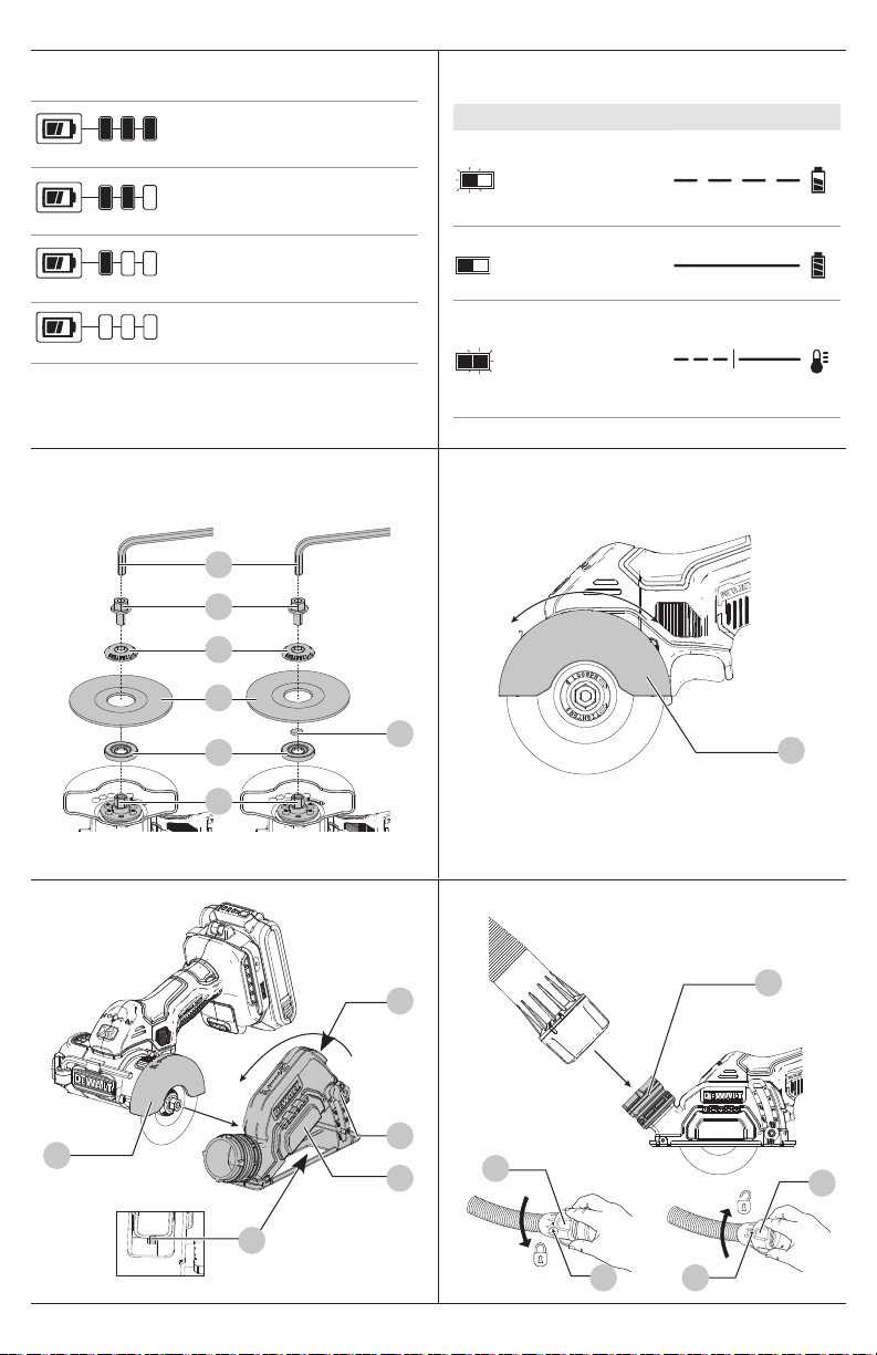
Fuel Gauge Battery Packs (Fig.B)
Some battery packs include a fuel gauge. When the fuel
gauge button is pressed and held, the LED lights will
indicate the approximate level of charge remaining. This
does not indicate tool functionality and is subject to
variation based on product components, temperature, and
end‑userapplication.
Transportation
WARNING: Fire hazard. Do not store, carry, or
transport the battery pack so that metal objects
can contact exposed battery terminals. For
example, do not place the battery pack in aprons,
pockets, tool boxes, product kit boxes, drawers, etc.,
with loose nails, screws, keys, coins, hand tools, etc.
When transporting individual battery packs, make
sure that the battery terminals are protected and well
insulated from materials that could contact them and
cause a short circuit. NOTE: Li‑ion battery packs should
not be put in checked baggage on airplanes and must
be properly protected from short circuits if they are in
carry‑onbaggage.
the cap or in a tool, the pack is one battery at the Watt hour
rating labeled“Use”.
Example battery pack label:
USE: 120 Wh SHIPPING: 3 x 40 Wh
In this example, the battery pack is three batteries with
40Watt hours each when using the cap. Otherwise, the
battery pack is one battery with 120Watthours.

ENGLISH
10
NOTE: To remove the battery pack, some chargers
require the battery pack release button to bepressed.
Hot/Cold Pack Delay
When the charger detects a battery pack that is too hot
or too cold, it automatically starts a Hot/Cold Pack Delay,
suspending charging until the battery pack has reached an
appropriate temperature. The charger then automatically
switches to the pack charging mode. This feature ensures
maximum battery packlife.
A cold battery pack may charge at a slower rate than a warm
batterypack.
The hot/cold pack delay will be indicated by the red light(s)
continuing to blink but with the yellow light continuously
ON. Once the battery pack has reached an appropriate
temperature, the yellow light will turn OFF and the charger
will resume the chargingprocedure.
DCB118 and DCB1112 Chargers
The DCB118 and DCB1112 chargers are equipped with
an internal fan designed to cool the battery pack. The fan
will turn on automatically when the battery pack needs to
becooled.
Never operate the charger if the fan does not operate
properly or if ventilation slots are blocked. Do not permit
foreign objects to enter the interior of thecharger.
Electronic Protection System
Li‑Ion tools are designed with an Electronic Protection
System that will protect the battery pack against overloading,
overheating or deep discharge. The tool will automatically
turn off and the battery pack will need to berecharged.
Important Charging Notes
1. Longest life and best performance can be obtained if
the battery pack is charged when the air temperature
is between 65°F – 75°F (18°C– 24°C). DO NOT charge
when the battery pack is below +40°F (+4.5°C), or
above +104°F (+40°C). This is important and will
prevent serious damage to the batterypack.
2. The charger and battery pack may become warm to the
touch while charging. This is a normal condition, and
does not indicate a problem. To facilitate the cooling of
the battery pack after use, avoid placing the charger or
battery pack in a warm environment such as in a metal
shed or an uninsulatedtrailer.
3. If the battery pack does not charge properly:
a. Check operation of receptacle by plugging in a lamp
or other appliance;
b. Check to see if receptacle is connected to a light
switch which turns power off when you turn out
the lights;
c. If charging problems persist, take the tool, battery
pack and charger to your local servicecenter.
4. You may charge a partially used pack whenever you
desire with no adverse effect on the batterypack.
Charger Cleaning Instructions
WARNING:Shock hazard. Disconnectthe charger
from the AC outlet before cleaning. Dirt and grease
plugged together, and nameplate ampere rating. If in
doubt, use the next heaviergauge.
Minimum Gauge for Cord Sets
Volts Total Length of Cord in Feet
(meters)
120V 25 (7.6) 50 (15.2) 100 (30.5) 150 (45.7)
Ampere Rating
American Wire Gauge
More Than Not More
Than
0 6 18 16 16 14
610 18 16 14 12
10 12 16 16 14 12
12 16 14 12 Not Recommended
• Do not place any object on top of the charger or place
the charger on a soft surface that might block the
ventilation slots and result in excessive internal heat.
Place the charger in a position away from any heat source.
The charger is ventilated through slots in the top and the
bottom of thehousing.
• Do not operate the charger with a damaged cord
orplug. Have them replacedimmediately.
• Do not operate the charger if it has received a sharp
blow, been dropped or otherwise damaged in any
way. Take it to an authorized servicecenter.
• Do not disassemble the charger; take it to an
authorized service center when service or repair
is required. Incorrect reassembly may result in a risk of
electric shock, electrocution orfire.
• The charger is designed to operate on standard
120V household electrical power. Do not attempt to
use it on any other voltage. This does not apply to the
vehicularcharger.
• Foreign materials of a conductive nature, such as, but
not limited to, grinding dust, metal chips, steel wool,
aluminum foil or any buildup of metallic particles
should be kept away from the charger cavities and
ventilation slots.
• Always unplug the charger from the power supply
when there is no battery pack in thecavity.
Charging a Battery (Fig. C, D)
1. Plug the charger into an appropriate outlet.
2. Insert and fully seat battery pack. The red charging
light(s) will continuously blink whilecharging.
3. Charging is complete when the red charging light(s)
remain(s) continuously ON. Battery pack can be left in
charger or removed. Some chargers require the battery
pack release button to be pressed forremoval.
WARNING: Only charge batteries in air temperature
over 40° F (4.5° C) and below 104° F (+40°C).
4. Charger will not charge a faulty battery pack, which may
be indicated by the charging light(s) staying OFF. Take
charger and battery pack to an authorized service center
if light(s) stay(s)OFF.
NOTE: Refer to label near charging light(s) on charger
for blinkpatterns. Older chargers may have additional
information and/or may not have a yellow indicatorlight.

11
ENGLISH
Adjusting the Guard Angle (Fig. E)
WARNING: Remove battery first. To reduce the risk of
injury when grinding, ALWAYS adjust the guard to
provide the best control and protection. ALWAYS wear
gloves to protect your hands when adjusting theguard.
You can adjust the angle of theguard.
1. Remove thebattery.
2. Grasp the guard12firmly and rotate to desiredangle.
The guard can rotate 30degrees, forward orbackward.
WARNING: To reduce the risk of injury, only use wheels
that are no greater than 3" (76mm) in diameter, have
an inner diameter of 3/8” (or 7/16” if using adapter
ring), and without cutting teeth. Thickness of wheel not
to exceed 0.09” (2.2mm). Never force a wheel onto the
machine or alter the size of the arborhole.
WARNING: Since accessories, other than those offered
by DeWALT, have not been tested with this product, use
of such accessories with this tool could be hazardous.
To reduce the risk of injury, only DeWALT recommended
accessories should be used with thisproduct.
1. Remove thebattery.
2. Lay unit on a firm surface, with the spindle15
facingupward.
3. Hold spindle lock button6 to keep the spindle
fromturning. Spindle threads are lefthand.
4. Using supplied 6mm wrench13, remove spindle
screw19, outer flange18, used wheel20 if one
is installed and inner flange16. Spindle threads are
lefthand.
5. Slip the inner flange over the spindle.
NOTE: When intsalling 7/16" wheels, place the 7/16"
adaptor17 over the innerflange.
6. Slip wheel over spindle. Make sure wheel goes over pilot
diameter of innerflange.
NOTE: When installing diamond*** wheels, always
match direction of rotation of the wheel to the desired
direction of rotation of the tool. Diamond*** wheels
will not cut effectively unless the direction marked on
the wheel matches the direction of rotation. Check the
setting of the forward/reverse/lock off button5 to make
sure it matches the direction marked on thewheel.
7. Slip on outer flange with the flat side towards the
cut‑offwheel.
NOTE: The text "LOOSE TIGHTEN" will be visible when
installedcorrectly.
8. Start threading on spindle screw which will self align
outer flange. Make sure the wheel is fitted in the
correctorientation.
9. Engage spindle lock button and tighten spindle screw
with wrench. Do not over tighten spindlescrew.
10. Turn wheel by hand to ensure it is properly centered. The
wheel should not hit the shoe, guard or spindle screw.
The spindle screw and flanges should betight.
Installing Wheels (Fig. A, D, J)
WARNING: Burn Hazard. Sharp parts. ALWAYS wear
gloves when changing wheels. Wheels have sharp
edges or may get extremely hot during operation, and
may damage barehands.
Wheels
WARNING: To minimize the risk of eye injury, always
use eye protection. Carbide is a hard but brittle
material. Foreign objects in the workpiece such as wire
or nails can cause tips to crack or break. Mount the
wheel securely in proper direction of rotation before
using, and always use a clean, sharpwheel.
WARNING: To reduce the risk of injury, only use wheels
that are no greater than 3" (76mm) in diameter, have
an inner diameter of 3/8” (or 7/16” if using adapter
ring), and without cutting teeth. Thickness of wheel not
to exceed 0.09” (2.2mm). Never force a wheel onto the
machine or alter the size of the arborhole.
A dull wheel will cause slow inefficient cutting, overload the
motor, could cause excessive splintering, and could increase
the possibility of kickback. Please refer to the table below to
determine the correct wheel for yourapplication.
Wheel type Application
Diamond*** Multi‑Material
Wheel (DW8530)
Drywall, fiber cement, plastic, steel, non
ferrous materials
Bonded Abrasive Wheel
(DW8711)
Steel, stainless steel, non‑ferrous materials
Diamond*** Tile Wheel
(DW47350)
Ceramic Tile, Porcelain and Granite/Marble/
Stone
ASSEMBLY AND ADJUSTMENTS
WARNING: To reduce the risk of serious personal
injury, turn unit off and remove the battery pack
before making any adjustments or removing/
installing attachments or accessories. An
accidental start‑up can causeinjury.
Wall Mounting
Some DeWALT chargers are designed to be wall mountable
or to sit upright on a table or work surface. If wall mounting,
locate the charger within reach of an electrical outlet, and
away from a corner or other obstructions which may impede
air flow. Use the back of the charger as a template for the
location of the mounting screws on the wall. Mount the
charger securely using drywall screws (purchased separately)
at least 1” (25.4mm) long, with a screw head diameter of
0.28–0.35” (7–9mm), screwed into wood to an optimal
depth leaving approximately 7/32” (5.5 mm) of the screw
exposed. Align the slots on the back of the charger with the
exposed screws and fully engage them in theslots.
SAVE THESE INSTRUCTIONS FOR
FUTURE USE
may be removed from the exterior of the charger using
a cloth or soft non‑metallic brush. Do not use water or
any cleaningsolutions.

ENGLISH
12
To Operate (Fig. A)
CAUTION: Before attempting to start, grasp toolfirmly.
WARNING: To reduce the risk of injury, DO NOT use a
toothed blade.
WARNING: This tool is intended to be used dry.
If water cooling is necessary, use a spray bottle
with clean water to lightly wet surface only, avoid
over‑wetting the workpiece. NEVER immerse your tool
or battery pack in any liquid or allow liquid insidethem.
Forward/Reverse/Lock Off Button (Fig. A)
Your cut‑off tool is equipped with a forward/reverse/lock
off button5. Some applications or accessories may require
the tool to be run in forward or reverse. When making a cut,
select the direction of cut that allows the tool to be pushed
away from your body. When installing a diamond wheel,
select the rotation that matches the arrow on the wheel.
• For forward (clockwise) rotation, push the forward/
reverse/lock off button all the way to the right, as shown
by the direction indicator7.
• For reverse (counterclockwise) rotation, push the
forward/reverse/lock off button all the way to the left, as
shown by the directionindicator.
• To lock the trigger switch, push the forward/reverse/
lock off button to the centre position, as shown by the
directionindicator.
Proper Hand Position (Fig. I)
WARNING: To reduce the risk of serious personal injury,
ALWAYS use proper hand position asshown.
WARNING: To reduce the risk of serious personal
injury, ALWAYS hold securely in anticipation of a
suddenreaction.
WARNING: Keep your free hand far from
cuttingaction. Do not reach underneath the workpiece.
Proper hand position requires one hand on the main
handle3.
Installing and Removing the Battery Pack
(Fig. H)
NOTE: For best results, make sure your battery pack is
fullycharged.
To install the battery pack8 into the tool handle, align the
battery pack with the rails inside the tool’s handle and slide
it into the handle until the battery pack is firmly seated in the
tool and ensure that it does notdisengage.
To remove the battery pack from the tool, press the release
button2 and firmly pull the battery pack out of the tool
handle. Insert it into the charger as described in the charger
section of thismanual.
OPERATION
WARNING: To reduce the risk of serious personal
injury, turn unit off and remove the battery pack
before making any adjustments or removing/
installing attachments or accessories. An
accidental start‑up can causeinjury.
Attaching an AirLock™Compatible Dust
Extractor (Fig. G)
WARNING: Do not use dust extraction when cutting
metal. Swarf from metal cutting may be hot and may
spark which can melt vacuum hoses and may cause a
fire inside thevacuum.
WARNING: When using dust extraction, empty
vacuum before work begins and often during work.
Use care in disposing of dust. Materials in fine dust can
beexplosive.
Your tool is compatible with the DeWALT AirLock™
connection system. The AirLock™ allows for a fast, secure
connection between the AirLock™ connector23 and your
tool's dust extraction port8.
1. Remove thebattery.
2. Ensure the collar on the AirLock™ connector is in the
unlock position. (Refer to FigureG.) Align notches24 on
collar and AirLock™ connector as shown for unlock and
lockpositions.
3. Push the AirLock™ connector onto the adapter
connectorpoint.
4. Rotate the collar to the lockedposition.
NOTE: The ball bearings inside collar lock into slot and
secure the connection.The power tool is now securely
connected to the dustextractor.
Mounting, Removing and Adjusting the
Dust Shroud (Fig. F)
NOTE: The dust shroud is only for tile/concrete and drywall
cutting applications to connect to a vacuum for dust
collecting. We do not recommend use of the shroud for
metal cuttingapplications.
1. Remove thebattery.
2. With the wheel properly installed, rotate the guard12
all the wayforward.
3. Loosen the depth of cut wing nut11 and fully extend
the shoe. Hand‑tighten the depth of cutknob.
4. Maneuver the upper guard and wheel into the dust
shroud assembly9 and rotate tool to lock in place.
The front of the guard will rest against the stop inside
the assembly, and the back of the guard will catch the
release tab21.
To Remove the Dust Shroud
1. Remove thebattery.
2. Loosen the depth of cut wing nut and fully extend the
shoe. Hand‑tighten the depth of cut wingnut.
3. Press in the shroud release button22 and rotate the tool
out of the dust shroudassembly.
To Adjust the Depth of Cut
1. Loosen the depth of cut wing nut and slide the shroud
up or down. Use the markings on the depth of cut gauge
to help determine proper depth. Adjust the cutting
depth to the thickness of the workpiece. Less than 1/4" of
the wheel should be visible below theworkpiece.

13
ENGLISH
Lanyard Connection (Fig. A)
Optional Accessory
Safety Warnings Specific for Use At Height
WARNING:
• If the tool is dropped for any reason, the lanyard
attachment point and battery strap components
must be inspected and properly serviced prior to
re‑use. The lanyard attachment point is designed
to stretch to absorb the shock of a drop. Any
permanent stretch to the device exposing the
red marked internal coils indicates it has been
compromised and must be serviced prior toreuse.
• Remove any wrenches/chuck keys and store them
separately when using atheight.
• Do not use hang hook as lanyard
attachmentpoint.
Accessories
WARNING: Since accessories, other than those
offered by DeWALT, have not been tested with this
product, use of such accessories with this tool could be
hazardous. To reduce the risk of injury, only DeWALT
recommended accessories should be used with
thisproduct.
Recommended accessories for use with your tool are
available at extra cost from your local dealer or authorized
service center. If you need assistance in locating any
accessory, please contact DeWALT call 1‑800‑4‑DeWALT
(1-800-433-9258) or visit our website: www.dewalt.com.
Cleaning
WARNING: Blow dirt and dust out of all air vents with
clean, dry air at least once a week. To minimize the risk
of eye injury, always wear ANSI Z87.1 approved eye
protection when performing thisprocedure.
WARNING: Never use solvents or other harsh
chemicals for cleaning the non‑metallic parts of the
tool. These chemicals may weaken the plastic materials
used in these parts. Use a cloth dampened only with
water and mild soap. Never let any liquid get inside the
tool; never immerse any part of the tool into aliquid.
MAINTENANCE
WARNING: To reduce the risk of serious personal
injury, turn unit off and remove the battery pack
before making any adjustments or removing/
installing attachments or accessories. An
accidental start‑up can causeinjury.
Your DeWALT power tool has been designed to operate
over a long period of time with a minimum of maintenance.
Continuous satisfactory operation depends upon proper tool
care and regularcleaning.
Transportation and Storage
During transportation and storage lock the trigger switch
with the lock‑offbutton.
Remove the battery pack during the toolstorage.
Tool Connect™ Chip (Fig.K)
WARNING: To reduce the risk of serious personal
injury, turn unit off and remove the battery pack
before making any adjustments or removing/
installing attachments or accessories. An
accidental start‑up can causeinjury.
Your tool is Tool Connect™ Chip ready and has a location for
installation of a Tool Connect™ Chip.
Tool Connect™ Chip is an optional application for your
smart device (such as a smart phone or tablet) that connects
the device to utilize the mobile application for inventory
management functions.
Refer to Tool Connect™Chip Instruction Sheet for
moreinformation.
Installing the Tool Connect™ Chip
1. Remove the retaining screws25 that hold the Tool
Connect™ Chip protective cover26into thetool.
2. Remove the protective cover and insert the Tool
Connect™ Chip into the empty pocket27.
3. Ensure that the Tool Connect™ Chip is flush with the
housing. Secure it with the retaining screws and tighten
thescrews.
4. Refer to Tool Connect™Chip Instruction Sheet for
furtherinstructions.
WARNING: Wheels used for cutting may break or kick
back if they bend or twist while the tool is being used to
do cut‑offwork.
WARNING: Do not bang or bump a cut‑off wheel
when starting or during acut.
1. Grasp main handle3firmly.
2. Line up wheel with material to be cut. Be sure nothing is
near or in line with thewheel.
3. Depress and hold trigger switch4 then slowly feed
wheel into work with firm pressure. Do not force the tool.
For maximum efficiency and wheel life, keep the wheel
speedhigh.
4. To stop tool, release trigger switch4.
If Using the Dust Shroud for Dust Collecting
(Fig.J)
1. Remove batterypack.
2. Adjust the depth of cut when using the dustshroud.
3. Insert the batterypack.
4. While cutting, keep the shoe flat against the workpiece
and maintain a firm grip, don’t force the cut off tool
through the workpiece. Forcing a cut off tool can
causekickback.
NOTE: If making a partial cut, restarting a cut, or
correcting cut direction. Allow the wheels to come to
a complete stop. To resume cutting, center the wheel
in the kerf (cutting slot)29, back and saw away from
cutting edge, pull the trigger and re‑enter the cutslowly.
5. To stop tool, release triggerswitch.

ENGLISH
14
Three Year Limited Warranty
For warranty terms, go to https://www.dewalt.com/Legal/
Warranty/3‑Year‑Limited‑Warranty.
To request a written copy of the warranty terms, contact:
Customer Service at DeWALT Industrial Tool Co., 701East
Joppa Road, Towson, MD 21286or call 1‑800‑4‑DeWALT
(1-800-433-9258).
LATIN AMERICA: This warranty does not apply to products
sold in Latin America. For products sold in Latin America,
see country specific warranty information contained in
the packaging, call the local company or see website for
warrantyinformation.
FREE WARNING LABEL REPLACEMENT: If your warning
labels become illegible or are missing, call 1‑800‑4‑DeWALT
(1-800-433-9258) for a freereplacement.
Register Online
Thank you for your purchase. Register your product nowfor:
• WARRANTY SERVICE: Registering your product will help
you obtain more efficient warranty service in case there is
a problem with yourproduct.
• CONFIRMATION OF OWNERSHIP: In case of
an insurance loss, such as fire, flood or theft, your
registration of ownership will serve as your proof
ofpurchase.
• FOR YOUR SAFETY: Registering your product will
allow us to contact you in the unlikely event a safety
notification is required under the Federal Consumer
SafetyAct.
• Register online at www.dewalt.com.
Repairs
The charger and battery pack are notserviceable. There are
no serviceable parts inside the charger or batterypack.
WARNING: To assure product SAFETY and RELIABILITY,
repairs, maintenance and adjustment (including brush
inspection and replacement, when applicable) should
be performed by a DeWALT factory service center or a
DeWALT authorized service center. Always use identical
replacementparts.
• Only use batteries that contain the integral battery
strap. Do not use unsecured batteries while the tool
is tethered. Unsecured batteries may detach from
the tool ifdropped.
• Always keep the tool and accessories tethered
when working "at height". (Maximum lanyard
length: 6.5 ft [2m].)
• Use only with lanyards appropriate for this tool
type and rated for at least 12.0 lbs (5.44Kg).
• Crush, cut or entanglement hazard. Do
not use near moving parts, mechanisms or
runningmachinery.
• Do not anchor the tool lanyard to anything on
your body. Anchor to a rigid structure that can
withstand the forces of a droppedtool.
• Make sure the lanyard is properly secure at each
end prior touse.
• Inspect tool and lanyard before each use for
damage and proper function (including fabric
and stitching). Do not use if damaged or not
functioningproperly.
• Do not alter the lanyard attachment point or use in
a manner other than as instructed in thismanual.
• Only attach tool to a lanyard with a locking
carabiner. Do not attach by looping or knotting the
lanyard. Do not use rope orcord.
• Electrical shock hazard. Be sure power is off when
working in high voltage areas. Some lanyards
areconductive.
• Dropped tools will swing on the lanyard, which
could cause injury or loss ofbalance.
• Do not carry the tool by the attachment point, the
battery strap or thelanyard.
• Do not attach more than one tool to eachlanyard.
• Only use appropriate DeWALT brand lanyard‑ready
attachment kit. NEVER modify tools to create
attachmentpoints.
• Only transfer the tool between hands while
properly balanced in a stableorientation.
• Do not attach lanyards to tool in a way that
keeps guards, switches or lock‑offs from
operatingproperly.
• Avoid getting tangled in thelanyard.
• Keep lanyard away from the cutting area of
thetool.
• Do not use lanyards or attachment devices to get
additional leverage from thetool.
• Do not use for personal fallprotection.
• Falling object hazard! Only change batteries,
accesories and attachments where a dropped
object won't cause a hazard below you. Consult
your Authority Having Jurisdication (AHJ) or site
supervisor for procedures for working atheight.
• Do not use the charger or contractor bag atheight.
• Use multi‑action or screw gate type carabiners. Do
not use single action spring clipcarabiners.
The lanyard ready mounting hole14 is for mounting the
DeWALT Lanyard Ready Attachment Point, available at a
DeWALT servicecenter.
The lanyard‑ready attachment kit is intended for use by
competent personnel who are trained and knowledgeable
regarding working with tools in and around machinery
and "at height". A lanyard‑ready attachment kit may only
be added to certain models and must be installed by an
authorized servicecenter.
Other manuals for DCS438
3
Table of contents
Other DeWalt Cut-off Machine manuals