Struers LaboPress-3 User manual

Manual No.: 15087003
Date of Release 11.01.2008
LaboPress-3
Instruction Manual


LaboPress-3
Instruction Manual
Table of Contents Page
User’s Guide ..............................................................1
Reference Guide.......................................................13
Quick Reference Card .............................................24
Always state Serial No and Voltage/frequency if you have technical questions or when ordering spare parts.
You will find the Serial No. and Voltage on the type plate of the machine itself. We may also need the Date
and Article No of the manual. This information is found on the front cover.
The following restrictions should be observed, as violation of the restrictions may cause cancellation of
Struers legal obligations:
Instruction Manuals: Struers Instruction Manual may only be used in connection with Struers equipment
covered by the Instruction Manual.
Service Manuals: Struers Service Manual may only be used by a trained technician authorised by Struers.
The Service Manual may only be used in connection with Struers equipment covered by the Service Manual.
Struers assumes no responsibility for errors in the manual text/illustrations. The information in this manual is
subject to changes without notice. The manual may mention accessories or parts not included in the present
version of the equipment.
The contents of this manual is the property of Struers. Reproduction of any part of this manual without the
written permission of Struers is not allowed.
All rights reserved. © Struers 2008.
Struers A/S
Pederstrupvej 84
DK-2750 Ballerup
Denmark
Telephone +45 44 600 800
Fax +45 44 600 801


LaboPress-3
Instruction Manual
LaboPress-3
Safety Precaution Sheet
To be read carefully
before use
1. The operator should be fully aware of the use of the machine according
to the Instruction Manual.
2. The machine must be placed in a well ventilated room on a working
table with adequate height for convenient operation.
3. Be sure that the actual voltage corresponds to the voltage stated on the
back of the machine and on the heating/cooling unit. The machine must
be earthed.
4. Be sure that the water connections are mounted correctly and without
leaks. The main water supply should be turned on when the machine is
in use.
Struers recommend that the mains water supply is shut off or
disconnected if the machine is to be left unattended
5. Be sure that the outlet hose is safely attached to the water outlet
system.
6. Be sure that the mounting unit is correctly assembled on the press
before starting the process.
7. Be sure that the top closure with upper ram is either correctly mounted
on the mounting cylinder or completely removed from the mounting
cylinder before starting the press.
8. Do not operate the mounting press with a higher force/pressure than
recommended for the actual cylinder diameter and resin in Struers
Application Guide for Hot Mounting.
9. Following a heating cycle, ensure the mounting cylinder is cooled for a
minimum of two minutes before opening.
10. Do not operate the machine whilst assembling or disassembling the
mounting unit.
The equipment is designed for use with consumables supplied by Struers. If subjected to misuse, improper
installation, alteration, neglect, accident or improper repair, Struers will accept no responsibility for
damage(s) to the user or the equipment.
Dismantling of any part of the equipment, during service or repair, should always be performed by a qualified
technician (electromechanical, electronic, mechanical, pneumatic, etc.).


LaboPress-3
Instruction Manual
1
User’s Guide
Table of Contents Page
1. Getting Started
Checking the Contents .....................................................................2
LaboPress-3................................................................................ 2
Mounting Unit ........................................................................... 2
Unpacking LaboPress-3.................................................................... 2
Placing LaboPress-3 ......................................................................... 2
Transport Screw Cap........................................................................ 2
Getting Acquainted with LaboPress-3............................................. 3
Noise Level........................................................................................4
Supplying Power............................................................................... 4
Supplying Water ............................................................................... 4
Water Inlet.................................................................................4
Water Outlet.............................................................................. 4
Assembling the Mounting Unit........................................................ 5
Removing the Cover .................................................................. 5
Installing the Lower Ram .........................................................5
Installing the Mounting Unit.................................................... 5
Installing the Cover................................................................... 6
Installing the Dust Protection Ring ......................................... 6
Disassembling the Mounting Unit................................................... 6
Dropping the Lower Ram.......................................................... 6
Removing the Dust Protection Ring ......................................... 6
Removing the Cover .................................................................. 6
Removing the Mounting Unit ..........................................................7
Removing the Lower Ram ................................................................ 7
Changing the Mounting Unit........................................................... 7
2. Basic Operations
Using the Controls............................................................................ 8
Front Panel Controls of LaboPress-3 .......................................8
Acoustic Signals......................................................................... 8
Main Switch............................................................................... 8
Placing the Specimen .....................................................................10
Pouring Resin over the Specimen........................................... 10
Placing Two Specimens .................................................................. 10
Installing the Top Closure.............................................................. 11
Starting the Mounting Process ...................................................... 12
Preheating with Low Pressure ............................................... 12
Stopping the Mounting Process ..................................................... 12
Removing the Top Closure .............................................................12

LaboPress-3
Instruction Manual
2
1. Getting Started
In the packing box you should find the following parts:
1 LaboPress-3 machine
1 Pressure hose
1 Filter gasket
1 Gasket
1 Reduction ring with gasket
2Measuring spoonsfor mounting resin
1 Funnel
1 Air filter
1 Set of Instruction manuals
1 Mounting unit
1 Top closure with upper ram
1 Lower ram
1 Dust protection ring
1 Piston pin
1 Mould release agent (FASTI)
1 Scraper (PROAN)
LaboPress-3 is detached from the bottom of the packing case by
removing the four screws from below.
LaboPress-3 should be placed on a steady table with an adequate
working height. The machine must be placed close to the power
supply, water mains and water outlet facilities. If water
recirculation is used, there must be room under the table for the
Recirculation Cooling Unit (TRECI).
Carry out the following procedure before using the machine for
the first time. Exchange the transport screw cap with the
enclosed air filter , to equalise the pressure in the hydraulic
system.
Checking the Contents
LaboPress-3
Mounting Unit
Unpacking LaboPress-3
Placing LaboPress-3
Transport Screw Cap
The transport screw cap is situated
underneath the cover for the mounting unit.

LaboPress-3
Instruction Manual
3
Take a moment to familiarise yourself with the location and
names of the LaboPress-3 components.
Front panel
Top closure
Main switch
Mounting unit
Dust protection ring
Cover for mounting unit
Top closure holder
Getting Acquainted with
LaboPress-3
➀
➅
➃
➄➁
➂
➆

LaboPress-3
Instruction Manual
4
The noise level of the machine is 60 dB (A) measured when the
pump is running, at a distance of 1.0 m/39.4” from the machine.
LaboPress-3 is factory mounted with an electric cable. Mount a
plug on the cable:
Brown: phase
Blue: neutral
Yellow/green: earth
Water for cooling may be supplied from the water mains or a
Recirculation Cooling Unit.
Mount the pressure hose onto the water inlet tube (pos.1) on the
back of the machine:
Insert the filter gasket in the coupling nut with the flat side
against the pressure hose.
Tighten the coupling nut completely.
Mount the other end of the pressure hose on the water mains tap
for cold water:
Mount the reduction ring with gasket on the water mains tap,
if necessary.
Introduce the gasket and tighten the coupling nut completely.
Lead the water outlet tube (pos. 2) to the drain and be
absolutely sure to place the hose with a steady downward
slope and without any obstructions.
Attach the water outlet tube to the water outlet system.
Noise Level
Supplying Power
IMPORTANT
Check that the mains voltage corresponds to the voltage stated on the type
plate on the machine. Do not operate the machine before the transit screw
cap has been exchanged with the enclosed air filter.
Supplying Water
➀
➃
➄
➁
Water Inlet
Water inlet
Water outlet tube IMPORTANT
Only connect to cold water
Water Outlet

LaboPress-3
Instruction Manual
5
Press the catch (pos. 4).
Press gently on both sides of the cover to release it, and lift it
up.
➀
➃
➄
➁
Catch
Place the lower ram on the top of the piston rod.
Turn the lower ram so that the holes in the axle journal on
top of the rod and ram line up, and insert the piston pin.
Make sure that the ends of the pin do not protrude.
➀
➂
➃
➄
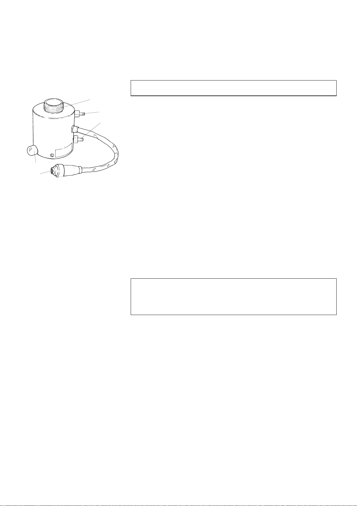
➁
Mounting cylinder
Fixation screw
Upper quick coupling for cooling water
Lower quick coupling for cooling water
Plug
Assembling the Mounting Unit
Removing the Cover
Installing the Lower Ram
IMPORTANT
The axle journal is part of the machine’s safety mechanism to protect
against damage to the machine. Please see: Maintenance. If it breaks, it
must only be replaced with a Struers replacement part or the safety
mechanism may not function.
Installing the Mounting Unit
IMPORTANT
Do not operate the machine whilst installing the mounting unit

LaboPress-3
Instruction Manual
6
Unscrew the fixation screw about 10 mm.
Place the mounting cylinder over the lower ram with the
fixation screw in the position shown.
Turn the mounting unit in a clockwise direction until it stops.
Tighten the fixation screw completely.
Mount the tube with the straight quick coupling on the lower
quick coupling (position 4) of the mounting unit and push to
connect. Make sure that the ring comes to stop in the extreme
end of the quick coupling.
Mount the tube with the elbow quick coupling on the upper
quick coupling of the mounting unit (pos. 3) and push to
connect. Make sure that the ring comes to stop in the extreme
end of the quick coupling.
Mount the plug (pos. 5) in the socket. Tighten the coupling
nut.
Insert the barb into the front of the opening for the cover.
Insert the barbs on both sides of the cover into the cabinet.
Press the sides of the cabinet gently.
Press the rear end of the cover in so that the catch engages.
Place the dust protection ring around the mounting cylinder. The
concave side should face upwards.
Switch on the main power of the machine.
Press the key RAM DOWN Nto lower the ram to its lower
limit.
Lift out the dust protection ring.
Press the catch (position 4 above).
Press gently on both sides of the cover, to release it, and lift it
up.
Installing the Cover
➀
➃
➄
➁
Catch
Installing the
Dust Protection Ring
Disassembling
the Mounting Unit
Dropping the Lower Ram
Removing the
Dust Protection Ring
Removing the Cover
LaboPress-3
Instruction Manual
7
Mounting cylinder
Fixation screw
Upper quick coupling for cooling water
Lower quick coupling for cooling water
Plug
Disconnect the plug (pos. 5) in the socket. Loosen the coupling
nut and pull.
Disconnect the tube with elbow quick coupling on the upper
quick coupling on the mounting unit (pos. 3). Pull the ring.
Wait 5 seconds to allow the water to flow out of the cooling
coil.
Disconnect the tube with straight quick coupling on the lower
quick coupling on the mounting unit (pos. 4). Pull the ring.
Unscrew the fixation screw about 10 mm.
Turn the mounting unit in an anti-clockwise direction until it
stops.
Lift the mounting unit.
Push the piston pin out of the lower ram and lift it off.
Follow the instructions for Removing the Mounting Unit and
Installing the Mounting Unit.
IMPORTANT
Do not operate the machine whilst removing the mounting unit
Removing the Mounting Unit
➀
➂
➃
➄
➁
Removing the Lower Ram
IMPORTANT
The axle journal is part of the machine’s safety mechanism to protect
against damage to the machine. Please see: Maintenance. If it breaks, it
must only be replaced with a Struers replacement part or the safety
mechanism may not function.
Changing the Mounting Unit
LaboPress-3
Instruction Manual
8
2. Basic Operations
Short Beep: when a key is pressed, a short beep indicates
that the command has been accepted.
Long Beep: a long beep indicates that the key is inactive at
that moment.
Three long beeps: indicate that the mounting process is
finished.
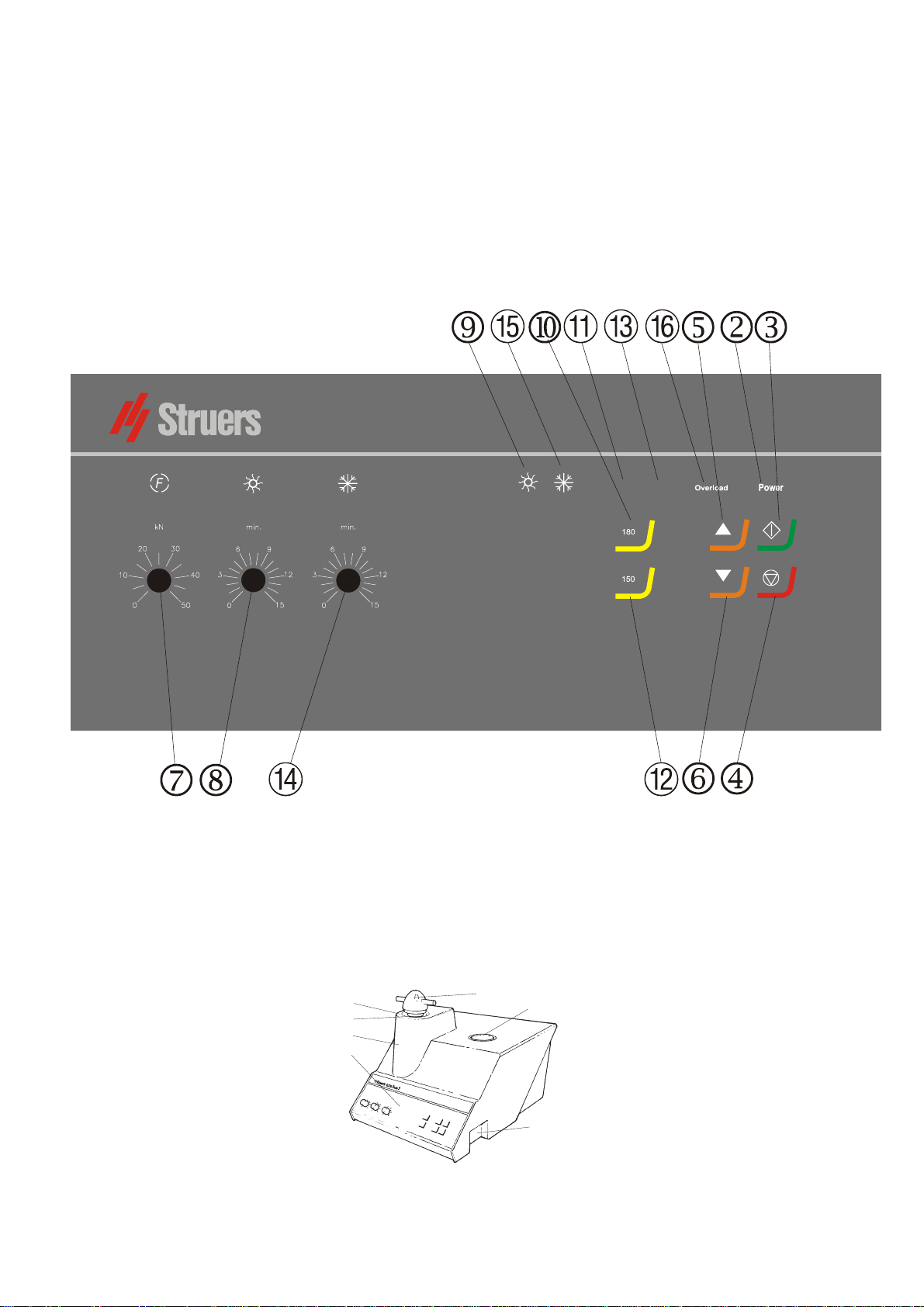
cFront panel
eMain switch
Using the Controls
Front Panel Controls of
LaboPress-3
A
coustic Signals
➀
➅
➃
➄➁
➂
➆
Main Switch
180°C
150°C
LaboPress-3

LaboPress-3
Instruction Manual
9
Pos. No. Key/Knob Function Pos. No. Key/Knob Function
MAIN
SWITCH
Turns the main power of the machine
on/off. The main switch is located to
the right of the cabinet.
HEATING
INDICATOR
¹Lights up when heating is on.
POWER
POWER Lights up when the main power is on.
HEATING
180°C Selects a heating temperature of
180°C.
START s Starts the automatic mounting
process. 1
HEATING
INDICATOR
180°C Lights up when the heating
temperature is set to 180°C.
STOP o Stops the mounting process,
followed by automatic release of
pressure. Stops the movement of the
lower ram.
2
HEATING
150°C Selects a heating temperature of
150°C.
RAM
UP
O Starts the upward movement of
lower ram. When started: stops the
upward movement of the lower ram.
The ram automatically stops when
the upper limit is reached.
3
HEATING
INDICATOR
150°C Lights up when the heating
temperature is set to 150°C.
RAM
DOWN
N Starts the downward movement of
lower ram. When started: Stops the
downward movement of the lower
ram. The ram automatically stops
when the lower limit is reached.
4
COOLING ¸
Adjustable knob for setting the
cooling time.
FORCE f
Adjustable knob for setting the force
(pressure). 5
COOLING
INDICATOR ¸
Lights up when cooling is on.
HEAT ¹
Adjustable knob for setting the
heating time. 6
OVERLOAD
OVERLOAD Lights up if the motor has been
overloaded.

LaboPress-3
Instruction Manual
10
Press and hold RAM UP Oto raise the lower ram to its upper
limit.
Apply “Mould Release Agent” to the surface of the lower ram.
Place the specimen on the ram. The specimen must be clean,
dry and free from grease. The distance between the specimen
and the cylinder wall must be minimum 3 mm to avoid cracks
in the resin.
Press and hold RAM DOWN Nto lower the ram to its lower
limit.
Fill a suitable amount of resin into the cylinder by means of
the enclosed funnel.
Always make sure there is sufficient resin to cover the sample
after compression. Please note that the volume of the resin
reduces when the granulate becomes compressed. If insufficient
resin is used, the rams may come in contact with the sample, and
the cylinder may be damaged.
Follow the instructions in Placing the Specimen.
Apply “Mould Release Agent” to all surfaces of the
intermediate ram.
Place the intermediate ram on top of the resin.
Place the second specimen on the intermediate ram and fill
the cylinder with an adequate quantity of resin.
Again, make sure you use adequate resin!
Placing the Specimen
Pouring Resin over the Specimen
Important
The “Mould Release Agent” must always be applied to the mounting rams
as a thin layer to prevent the resins sticking to the surface. By means of
Struers AntiStick a thin layer of stearate powder can easily be dabbed on
the rams.
Placing Two Specimens

LaboPress-3
Instruction Manual
11
Remove resin dust from the upper part of the mounting
cylinder.
Clean the cylindrical surface of the upper ram. Cured resin
can easily be removed without damage to the surface of the
ram using the scraper supplied.
Apply “Mould Release Agent” to all accessible surfaces of the
upper ram.
Place the top closure with the upper ram on the mounting
cylinder.
Press the top closure straight down, turning it counter-
clockwise until you hear a click.
Press the top closure down and turn it clockwise until its
lower limit.
Turn the top closure a quarter of a turn back.
Installing the Top Closure
Important
If the ram does not fit in the cylinder then check ram and cylinder for cured
resin. The tolerance between the cylinder and the ram is very fine and even
small amounts of resin from previous mounting may cause problems.

LaboPress-3
Instruction Manual
12
Set the force.
Set the heating time.
Set the heating temperature (180/150°C).
Set the cooling time.
Press START s, and the process will run automatically.
The mounting process can be followed on the heating and
cooling indicators.
Set the force to a low value to begin with. Adjust the force after
the desired period of preheating.
The machine automatically stops and relieves the pressure
when the cooling time has elapsed. The machine can be
stopped at any time during the mounting process by pressing
STOP o.
When the mounting process is finished:
Turn the top closure counter-clockwise until released from the
threads.
Press RAM UP Oto raise the lower ram to its upper limit.
Place the top closure in the top closure holder.
Starting the Mounting Process
Preheating with Low Pressure
Stopping the Mounting Process
If you have stopped the machine during the mounting process:
Cool the mounting cylinder in minimum 2 min before opening, after a
heating period. Please note that the mount possibly will be destroyed.
Removing the Top Closure

LaboPress-3
Instruction Manual
13
Reference Guide
Table of Contents Page
1. Advanced Operations
Installation of Recirculation Cooling Unit (Optional) .................. 14
Socket for Recirculation .......................................................... 14
2. Struers Metalog Guide™ ............................................... 15
3. Application Guide for Hot Mounting........................ 15
4. Accessories ......................................................................... 16
5. Consumables....................................................................... 17
6. Trouble-Shooting............................................................... 18
7. Maintenance
Daily Service ................................................................................... 20
Monthly Service .............................................................................. 20
Cleaning under the Lower Ram.............................................. 20
Cleaning the Rams ......................................................................... 20
Removing the Upper Ram .............................................................. 21
Lubricating the Threads for the Top Closure................................ 21
Decalcifying the Cooling Coil in the Mounting Unit..................... 21
Replacing the Cooling Water.......................................................... 22
Checking the Recirculating Cooling Unit...................................... 22
8. Technical Data ................................................................... 23

LaboPress-3
Instruction Manual
14
1. Advanced Operations
A Recirculation Cooling Unit (TRECI) can be connected by means
of a Recirculation Cooling Unit Connector (ROPRE).
Connect the cable from the pump in TRECI to ROPRE, according
to the diagram of ROPRE.
Connect the cable with plug from ROPRE to the socket
(pos. 5) on the back of the mounting press.
Connect the cable from ROPRE to the mains.
Check that the pump rotates in the direction indicated on the
pump. If the direction is incorrect, switch two of the phases in
the connection to the pump in TRECI (3-phase versions only).
Replace the outlet tube on the pump in TRECI with the non-
return valve with elbow and hexagon nipple from ROPRE.
Struers recommends that you seal the threads.
Connect the pressure hose of the mounting press to the
hexagon nipple. Remember to mount the gasket.
Lead the outlet hose (pos. 2) to the inlet on TRECI. Be
absolutely sure to place the hose with a steady downward
slope and without obstructions.
Attach the water outlet to the inlet of TRECI.
Installation of Recirculation
Cooling Unit (Optional)
TRECI
LaboPress-3/
ProntoPress-10/ProntoPress-20
ROPRE
Socket for Recirculation
➀
➃
➄
➁
Outlet hose
Socket for recirculation
Table of contents
Languages:
Other Struers Power Tools manuals


Popular Power Tools manuals by other brands


Power Team
Power Team TWSD Series Operating instructions and parts list

Parkside
Parkside PAMFWP 20-LI A1 Translation of the original instructions

Lacewing
Lacewing EasyPress instruction manual

IVT
IVT JS-570SGP instruction manual

PROMAT
PROMAT 4000821885 Original instruction manual

Graco
Graco 127649 instructions


