Graco 127649 User manual

Instructions
AUTOMATIC SHUT-OFF NOZZLE FOR 333468A
DIESEL EXHAUST FLUID (DEF) (ISO 22241) EN • FR • ES
NOT APPROVED FOR USE IN EXPLOSIVE
ATMOSPHERES OR HAZARDOUS LOCATIONS
MODEL 127649
MAX WPR 345 kPa (3.4 bar) (50 psi)
Important Safety Instructions
Read all warnings and instructions in this manual.
Save these instructions

2 M0302
EN INDEX
A GENERAL WARNINGS 3
B FIRST AID RULES 3
B.1 WARNINGS 4
C THE DISPENSING NOZZLE 6
C.1 INTENDED USE 6
D TECHNICAL DATA 6
E INSTALLATION 6
F MODES OF OPERATION 7
G PREVENTION MISFILLING (optional) 7
H PRELIMINARY CHECK 8
I INITIAL START UP 9
J MAINTENANCE 9
K MALFUNCTIONS 9
L DEMOLITION AND DISPOSAL 10
M DIMENSIONS 10
WARRANTY 12

M0302 3
EN
A GENERAL WARNINGS
Important
precautions
To ensure operator safety and to protect the pump from
potential damage, workers must be fully acquainted with
this instruction manual before performing any operation.
Symbols used
in the manual
The following symbols will be used throughout the manual
to highlight safety information and precautions of particular
importance:
WARNING
This symbol indicates safe working practices for
operators and/or potentially exposed persons.
NOTICE
This symbol indicates that there is risk of damage to
the equipment and/or its components.
NOTE
This symbol indicates useful information.
Manual preser-
vation
This manual should be complete and legible throughout.
It should remain available to end users and specialist
installation and maintenance technicians for consultation at
any time.
Reproduction
rights
All reproduction rights are reserved by Graco Inc. The text
cannot be reprinted without the written permission
B FIRST AID RULES
Contact with
the uid In the event of problems developing following EYE/SKIN
CONTACT, INHALATION or INGESTION of the treated product,
please refer to the SAFETY DATA SHEET of the uid handled.
WARNING
EQUIPMENTMISUSEHAZARD
Keeptheproduct to be dispensed awayfromeyesandskin
Keeptheproduct to be dispensed out of reach of children
The nozzle must only be used for the purposes for which it
wasdesigned
Using unsuitable component parts and materials
could be hazardous
Not checking correct part installation could be hazard-
ous.

4 M0302
EN B.1 WARNINGS
The following warnings are for the setup, use, grounding, and repair of this equipment. The
exclamation point symbol alerts you to a general warning and the hazard symbols refer to
procedure-specic risks. When these symbols appear in the body of this manual or on warn-
ing labels, refer back to these Warnings. Product-specic hazard symbols and warnings not
covered in this section may apear thoughout the body of this manual where applicable.
WARNING
EQUIPMENT
MISUSE
!
Misuse can cause death
or serious injury Do not operate the unit when fatigued or un-
der the inuence of drugs or alcohol.
Do not exceed the maximum working pres-
sure or temperature rating of the lowest rated
system component. See Technical Data in all
equipment manuals.
Use uids and solvents that are compatible
with equipment wetted parts. See Technical
Data in all equipment manuals. Read uid
and solvent manufacturer’s warnings. For
complete information about your material,
request MSDS from distributor or retailer.
Do not leave the work area while equipment
is energized or under pressure.
Turn o all equipment when equipment is
not in use.
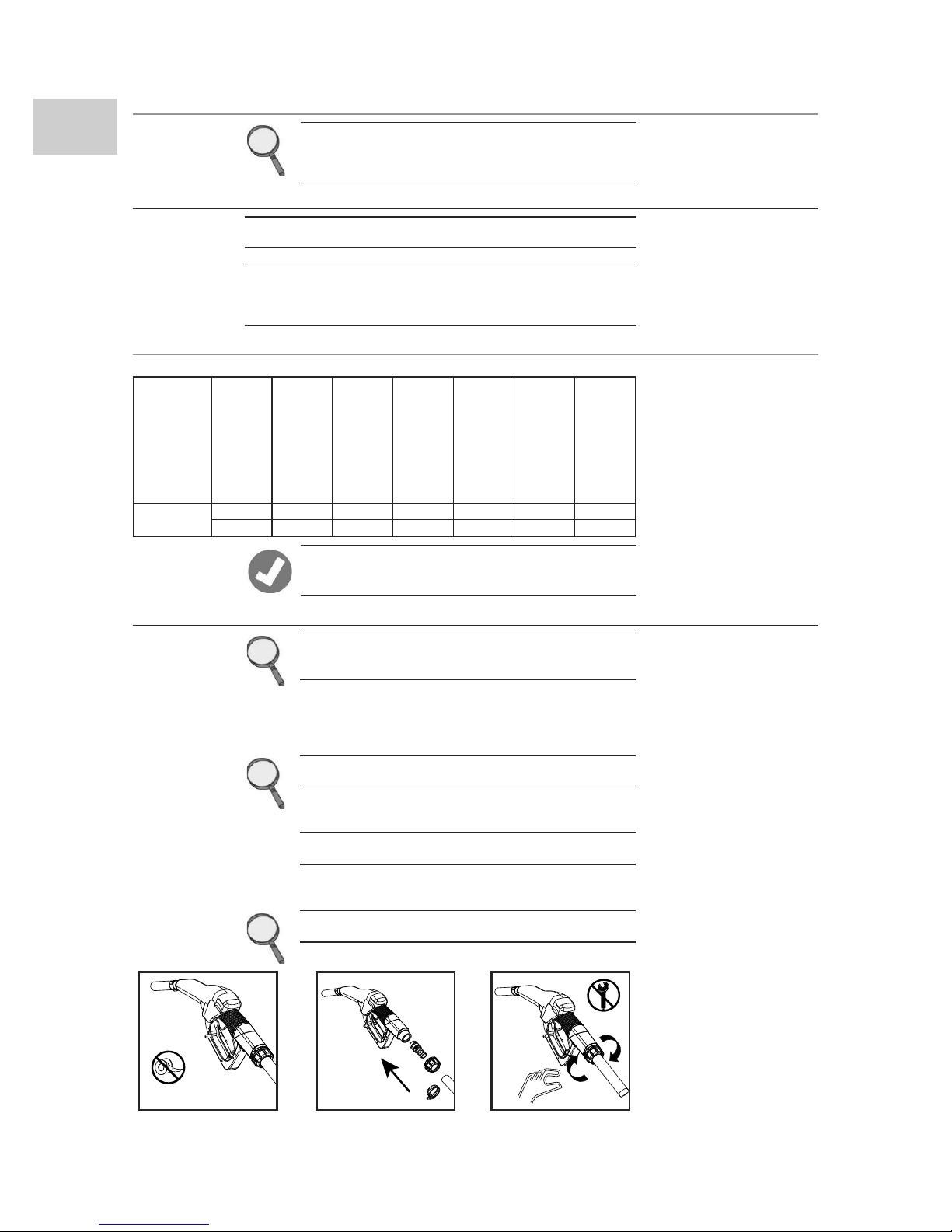
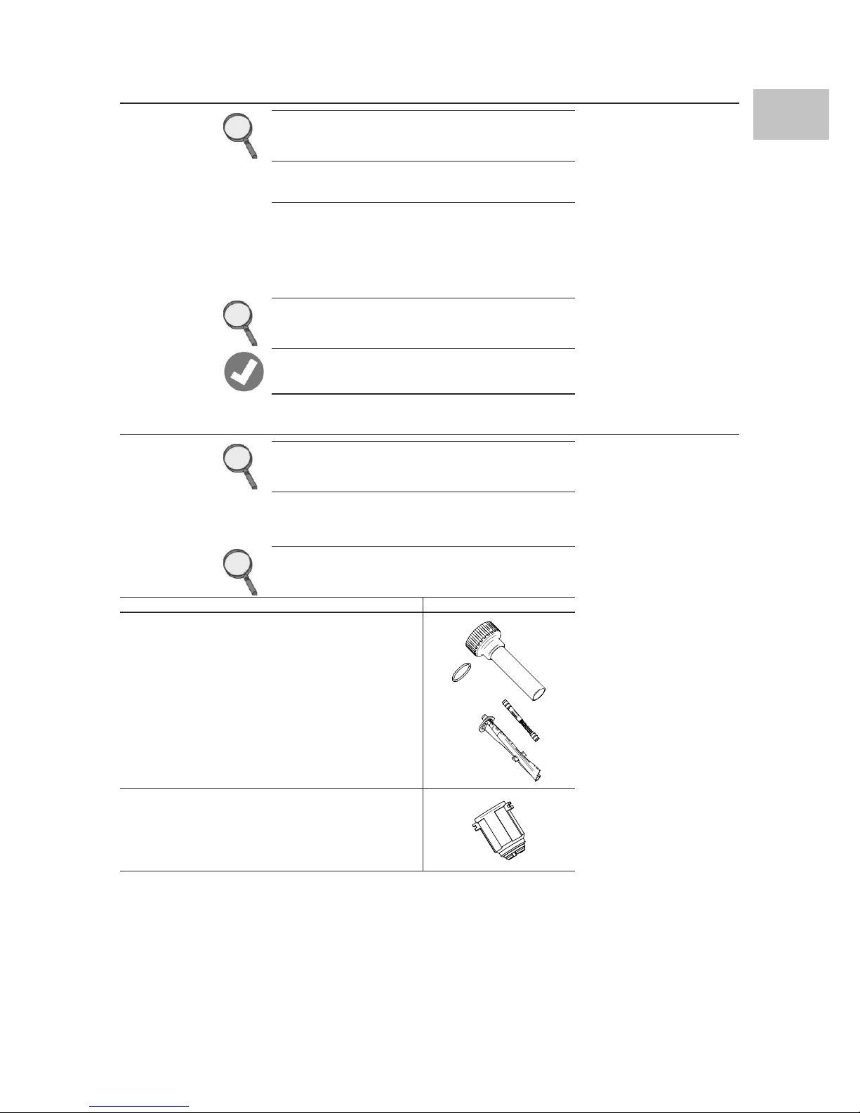
Checkequipmentdaily. Repair orreplaceworn
or damaged parts immediately with genuine
manufacturer’s replacement parts only.
Do not alter or modify equipment. Altera-
tions or modications may void agency ap-
provals and create safety hazards.
Make sure all equipment is rated and approved
for the environment in which you are using it.
Use equipment only for it intended purpose.
Call your distributor for information.
Routehoses andcables away fromtracareas,
sharp edges, moving parts, and hot surfaces.
Do not kink or over bend hoses or use hoses
to pull equipment.
Keep children and animals away from work area.
Comply with all applicable safety regulations.
Toxic Fluid
or Fumes
Hazard
Toxic uids or fumes can
cause serious injury or
death if splashed in the
eyes or on skin, inhaled, or
swallowed.
Read MSDS’s to know the specic hazards of
the uids you are using.
Store hazardous uid in approved contain-
ers, and dispose of it according to applicable
guidelines.
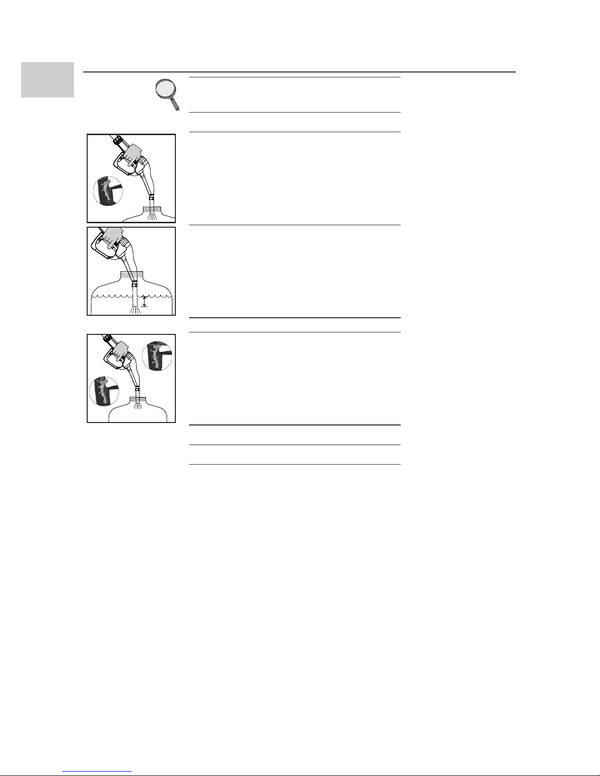
Prolonged contact with the treated product
may cause skin irritation: always wear protec-
tive gloves during dispensing.

M0302 5
EN
Personal
Protective
Equipment
Wear appropriate protec-
tive equipment when in
the work area to help pre-
vent serious injury, includ-
ing eye injury, hearing loss,
inhalation of toxic fumes,
and burns.
This equipment includes but is not limited to:
Protective eyewear, safety shoes, close-tting
clothing and hearing protection.
Respirators, protective clothing, and gloves as
recommended by the uid and solvent manu-
facturer.
Wear protective equipment that is suited to the
operations that need to be performed and re-
sistant to cleaning products.

6 M0302
EN C THE DISPENSING NOZZLE
FOREWORD DISPENSER NOZZLE FEATURING AUTOMATIC STOP DE-
VICE, MADE OF NON-CONDUCTIVE PLASTIC AND DE-
SIGNED TO BE USED WITH WATER/UREA SOLUTION (DEF,
AUS32). ALSO COMPATIBLE WITHWATER
C.1 INTENDED USE
P.N. 127649 WATER/UREA SOLUTION - D.E.F. - AUS 32, ACCORDINGTO DIN
70070
WATER
CONDITIONS
OF USE AND
ENVIRONMENTAL
CONDITIONS
Refer to the product technical data
D TECHNICAL DATA
Part number
Min. ow-rate
Max. ow-rate
Pressure loss at 35 l/
min (9.3 gpm)
Inlet thread with
swivel
External diameter
hose-end tting
Max. operating
pressure
Weight
127649 15 l/min 45 l/min 0.9 bar 1”GAS 20 mm 3.5 bar 0.6 Kg
4 gpm 12 gpm 13 psi 1”BSP .787 inc 50 psi 1.3 lb
NOTE The wetted materials used in this device are :
stainless steel, plastic and rubber suitable for AdBlue.
E INSTALLATION
FOREWORD The automatic nozzles are supplied ready for use.
The nozzle features SWIVEL hose-end tting (complete
with O-ring) useful for connecting to the supply hose.
TO ENSURE PERFECT OPERATION, THE DEVICE MUST BE
USEDTO DISPENSE FLUIDSWITH CHARACTERISTICS FALL-
INGWITHINTHE FOLLOWING PARAMETERS:
- Qmin .: 15 l/min / 4 gpm -- Qmax: 45 l/min / 12 gpm
- Pmin. : 1,5 bar / 22 psi - - Pmax: 3,5 bar / 50 psi
NOTICE During installation, use adequate sealants, being
careful no residues remain inside the hose.
So as not to negatively affect product operation,
couple the hose-end fitting with the hose without
using tools such as pliers, etc.
Assembly will be easier if the swivel hose-end fitting
is already fitted on the nozzle.
Make sure the hoses and the suction tank are with-
out threading scale or residues which could dam-
age the nozzle and the accessories.
NOTICE Apply adequate sealants on the male threads of the
connections and swivels
Do not use PTFE tape
NO PTFE TAPE

M0302 7
EN
F MODES OF OPERATION
FOREWORD The main feature of these nozzles is that they are easy to
use.
Two operating modes are available:
1
ASSISTED MODE Dispense by operating the nozzle lever. To interrupt dis-
pensing manually, release the lever.
2
AUTOMATICMODE Use the opening lever lock device for automatic dispens-
ing.
To continue dispensing after automatic stop, the lever
must be fully released before proceeding to operate it
again.
To interrupt dispensing in manual mode, press the lever
again, thereby releasing the device, and then release.
NOTICE Do not use the nozzle outside the parameters indi-
cated on the ”technical specifications” chart
NOTE Dispensing is automatically interrupted due to the
shut-off device, which operates when the level of the
liquid reaches the end of the spout.
G PREVENTION MISFILLING (optional)
PREMISE Refuelling with the nozzle equipped with“magnet switch”
is only possible in combination with the“magnet adapter”
, so misfuelling into tanks is made impossible
OPERATION The “magnet switch” is a xed magnetic eld within the
ller necks of the nozzle.This opens the magnet switch in
the spout, so it is only possible to dispense from the tank
where the magnet adaptor is installed.
NOTICE Nozzles equipped with “magnet switch” work only in
combination with the “magnet adapter”. The “mag-
net adapter” is an optional to be bought separately.
PART NUMBER DESCRIPTION PICTURE
127652 Magnet switch misl spout
127654 Magnet adapter misl
adapter (installs into DN40
ller necks only

8 M0302
EN H PRELIMINARY CHECK
NOTICE Check the correct operation of the lock device, ac-
cording to the following procedure:
1Take a graduated receptacle with a capacity of 20 litres (5
gal)
LOW
CLIP
2Begin dispensing into the receptacle, setting the lever in
the minimum ow position, until the receptacle is full.
5 cm
3Keeping the lever open, make sure the spout is sub-
merged by about 5 cm (2 inches).
4The nozzle must stop, with a click of the lever.
MEDIUM
CLIP HIGH CLIP
5Repeat the same operations with the lever in medium-
ow and maximum-ow position.
Check the correct operation of the stop device as de-
scribed above.
6If the nozzle stops during dispensing, check and reduce
the ow.
7If the dispensing stop device fails to operate, replace the
nozzle.

M0302 9
EN
I INITIAL START UP
FOREWORD Only start dispensing after making sure that assembly and
installation have been correctly performed.
WARNING TOXIC FLUIDOR FUMES HAZARD
Thefaultyoperationofthisdevicecould cause thespill
ofliquidsthat are hazardous for people andtheenvi-
ronment.
NOTICE It is a good practice to only operate the nozzle lever
after making sure the spout has been properly in-
serted in the mouth of the tank to be filled.
NOTICE When using for the first time and every time the
nozzle is used, following the connection of the sup-
ply hose, gently operate the lever to enable the air
to escape from the circuit, until normal operation is
achieved.
NOTICE Check the correct operation of the automatic stop
device once the tank is full.
NOTICE Keep fresh water in nozzle path to prevent DEF
crystals from forming on nozzle end. The nozzle au-
tomatic cut off may fail if crystallization plugs the
nozzle orifice. The nozzle tip must be submerged in
water when the nozzle is holstered.
J MAINTENANCE
1
PERIODICALLY CHECKTHE CORRECT OPERATION OFTHE AUTOMATIC
STOP DEVICE
2
IF FITTED, IT IS BEST TO PERIODICALLY CHECK THE FILTER AND CLEAN
IT EVERY 1000 LITRES OFTRANSFER.
3
PERIODICALLY CHECKTHE TIGHTNESS OFTHE CONNECTIONS
K MALFUNCTIONS
FOREWORD THE POSSIBLE CAUSES OF MALFUNCTION ARE MAINLY AT-
TRIBUTABLE TO THREE FACTORS:
1NOZZLE DIRTY IN INNER HOLE OF LIP AT END OF SPOUT
2OPERATING PRESSURE OF LIQUID TO BE DISPENSED BELOW
0.5 bar OR ABOVE 3.5 bar
3FLOW RATE TOO LOW OR TOO HIGH
NOTICE Correct and regular maintenance of the nozzle and
of the system to which it is connected prevents
malfunctions and possible accidental spills of haz-
ardous liquids.

10 M0302
EN L DEMOLITION AND DISPOSAL
Foreword If the system needs to be disposed, the parts which make it up
must be delivered to companies that specialize in the recycling and
disposal of industrial waste and, in particular:
Disposal of
packing materials The packaging consists of biodegradable cardboard which can be
delivered to companies for normal recycling of cellulose.
Disposal of metal
parts Metal parts, whether paint-nished or in stainless steel, can be
consigned to scrap metal collectors.
Disposal of electric
and electronic
components
These must be disposed of by companies that specialize in
the disposal of electronic components, in accordance with the
indications of directive 2002/96/CE (see text of directive below).
Information
regarding the
environment for
clients residing
within the
European Union
European Directive 2002/96/EC requires that all equipment marked
with this symbol on the product and/or packaging not be disposed
of together with non-dierentiated urban waste. The symbol
indicates that this product must not be disposed of together with
normal household waste. It is the responsibility of the owner to
dispose of these products as well as other electric or electronic
equipment by means of the specic refuse collection structures
indicated by the government or the local governing authorities.
Disposal of miscel-
laneous parts Other components, such as pipes, rubber gaskets, plastic parts and
wires, must be disposed of by companies specialising in the disposal
of industrial waste.
M DIMENSIONS
170
19
O
396
51
1'' BSP
170
19
O
51
1'' BSP

This page left intentionally blank

Graco Extended Warranty
Graco warrants all equipment referenced in this document which is manufactured by Graco and bearing its name to be free from
defects in material and workmanship on the date of sale to the original purchaser for use. With the exception of any special, ex-
tended, or limited warranty published by Graco, Graco will, for a period of twenty-four months from the date of sale, repair or re-
place any part of the equipment determined by Graco to be defective. This warranty applies only when the equipment is installed,
operated and maintained in accordance with Graco’s written recommendations.
This warranty does not cover, and Graco shall not be liable for general wear and tear, or any malfunction, damage or wear caused
by faulty installation, misapplication, abrasion, corrosion, inadequate or improper maintenance, negligence, accident, tampering,
or substitution of non-Graco component parts. Nor shall Graco be liable for malfunction, damage or wear caused by the incom-
patibility of Graco equipment with structures, accessories, equipment or materials not supplied by Graco, or the improper design,
manufacture, installation, operation or maintenance of structures, accessories, equipment or materials not supplied by Graco.
This warranty is conditioned upon the prepaid return of the equipment claimed to be defective to an authorized Graco distributor
for verication of the claimed defect. If the claimed defect is veried, Graco will repair or replace free of charge any defective parts.
The equipment will be returned to the original purchaser transportation prepaid. If inspection of the equipment does not disclose
any defect in material or workmanship, repairs will be made at a reasonable charge, which charges may include the costs of parts,
labor, and transportation.
THIS WARRANTY IS EXCLUSIVE, AND IS IN LIEU OF ANY OTHER WARRANTIES, EXPRESS OR IMPLIED, INCLUDING BUT NOT
LIMITEDTOWARRANTY OF MERCHANTABILITY OR WARRANTY OF FITNESS FOR A PARTICULAR PURPOSE.
Graco’s sole obligation and buyer’s sole remedy for any breach of warranty shall be as set forth above. The buyer agrees that no
other remedy (including, but not limited to, incidental or consequential damages for lost prots, lost sales, injury to person or
property, or any other incidental or consequential loss) shall be available. Any action for breach of warranty must be brought
within two (2) years of the date of sale.
GRACO MAKES NO WARRANTY, AND DISCLAIMS ALL IMPLIED WARRANTIES OF MERCHANTABILITY AND FITNESS FOR A
PARTICULAR PURPOSE, IN CONNECTION WITH ACCESSORIES, EQUIPMENT, MATERIALS OR COMPONENTS SOLD BUT NOT
MANUFACTURED BY GRACO. These items sold, but not manufactured by Graco (such as electric motors, switches, hose, etc.), are
subject to the warranty, if any, of their manufacturer. Graco will provide purchaser with reasonable assistance in making any claim
for breach of these warranties.
In no event will Graco be liable for indirect, incidental, special or consequential damages resulting from Graco supplying equip-
ment hereunder, or the furnishing, performance, or use of any products or other goods sold hereto, whether due to a breach of
contract, breach of warranty, the negligence of Graco, or otherwise.
FOR GRACO CANADA CUSTOMERS
The Parties acknowledge that they have required that the present document, as well as all documents, notices and legal proceed-
ings entered into, given or instituted pursuant hereto or relating directly or indirectly hereto, be drawn up in English. Les parties
reconnaissent avoir convenu que la rédaction du présente document sera en Anglais, ainsi que tous documents, avis et procé-
dures judiciaires exécutés, donnés ou intentés, à la suite de ou en rapport, directement ou indirectement, avec les procédures
concernées.
Graco Information
For the latest information about Graco products, visit www.graco.com.
TO PLACE AN ORDER, contact your Graco distributor or call to identify the nearest distributor.
Phone: 612-623-6928 orToll Free: 1-800-533-9655, Fax: 612-378-3590
All written and visual data contained in this document reects the latest product information available at the time of
publication. Graco reserves the right to make changes at any time without notice.
Original instructions.This manual contains English. MM 333468 / M0302
Graco Headquarters: Minneapolis
International Oces: Belgium, China, Japan, Korea
GRACO INC. AND SUBSIDIARIES • P.O. BOX 1441 • MINNEAPOLIS MN 55440-1441 • USA
Copyright 2014, Graco Inc. All Graco manufacturing locations are registered to ISO 9001.
www.graco.com
April 2014
M0302 rev.00
Table of contents
Other Graco Power Tools manuals

Graco
Graco InvisiPac GS35 Plug-Free User manual

Graco
Graco GrindLazer Standard DC21 E Guide

Graco
Graco Geo Blaster GB400 Guide

Graco
Graco 24T918 User manual

Graco
Graco EcoQuip 2 EQs User manual

Graco
Graco PRO 5500sc User manual

Graco
Graco 255828 Guide

Graco
Graco GrindLazer 25M992 User manual

Graco
Graco 249421 User manual

Graco
Graco 244766 Operation manual

Graco
Graco EcoQuip EQ200T Use and care manual

Graco
Graco Series A Operation manual

Graco
Graco EcoQuip Use and care manual

Graco
Graco GrindLazer 25M848 Guide

Graco
Graco HFR Manual instruction

Graco
Graco QuickShot 20B473 User manual

Graco
Graco RS 24P947 User manual

Graco
Graco GrindLazer 25M843 Use and care manual

Graco
Graco SERIES J Operation manual