Sawyer Excalibur Series User manual

Sawyer Manufacturing Company
7799 S. Regency Dr., Tulsa, OK 74131 USA
F918.834.0318
info@sawyermfg.com
We appreciate your business!
Congratulaons on your new SAWYER product. We are proud to
have you as our customer and will strive to provide you with the best
service and reliability in the industry. This product is backed by our
extensive warranty and world-wide service network. To locate your
nearest distributor or service agency, please contact us at the phone
number and address listed on the boom of each page.
You are in good company!
Sawyer Manufacturing Company is the world leader in the design
and manufacture of pipeline and welding equipment and has been
since 1948. Sawyer equipment has become a standard in the industry
and connues to set the benchmark for quality and durability.
This user operaon manual has been made to instruct you for the best
use and operaon of your Sawyer product. Your sasfacon with our
products is our main goal. Please read this enre manual carefully,
nong all ps, notes and warnings. Safety always comes rst.
About Us
Warranty
All products manufactured by or for Sawyer Manufacturing Company are
guaranteed against defects due to faulty workmanship or materials for twelve
months from the date of purchase.
This guarantee is limited to the repair or replacement of any parts found to be
defecve, and no other liability–expressed, implied, or conngent–is assumed.
Record the following informaon for warranty purposes:
Where purchased:________________________________________________
Purchase date:___________________________________________________
Equipment Serial #:_______________________________________________
P918.834.2550
sawyermfg.com
V1
AW
B
C
G
D
U
Excalibur Manual
Cold Cung Model 210
Parts Diagram - 210H
210H -
Oil (Hydraulic Driven)
210E - Electric (Electric Driven)
210P -
Air (Pneumac Driven)
L
K
E
F
I
J
O
N
QT
Q
V
A. Blade Speed Control
B. Start/Stop Control
C. Machine Direconal Control
D. Machine Speed Control
E. Feed Screw
F. Liing Cables
G. Liing Spring Clips
H. Blade Lowering/Raising Handle (not shown)
I. Blade Safety Cover
J. Cuer Spindle
K. Blade Safety Device
L. Cuer Lock Nut & Cuer Collar Support
M. Milling Cuer (not shown)
N. Lubricator Nozzle
O. Mist Lubricaon System Hose
P. Coolant Container (not shown)
Q. Guide Wheels
R. Guide Wheel Tracks (not shown)
S. Socket Head Cap Screws (not shown)
T. Hydraulic Hose Connector
U. Drive Chain (not shown)
V. Drive Chain Sprockets
W. Chain Tensioning Screw
X. Single Chain Pin (not shown)

Sawyer Manufacturing Company
7799 S. Regency Dr., Tulsa, OK 74131 USA
F918.834.0318
info@sawyermfg.com
P918.834.2550
sawyermfg.com
V1
Installation
1. Connecons and Power Sources
A. Hydraulic Machine
1. Connect machine to hydraulic power supply (Fig. 1) with the capability of
minimum pressure of 110 bars at 72 L/min. with 25 micron lter and air-
cooled heat exchanger.
2. Ensure power supply is connected properly by checking for clockwise rotaon
of blades.
3. Connect the Mist Lubricaon System Hose (O, Fig. 2) to the Coolant
Container (P). Use a synthec coolant oil type BIO/42 EP or similar.
Note: A small air compressor is required to operate the Automac Double Mist Lubricaon system.
4. Turn the Start/Stop Control (B, Fig. 3) to the On posion to ensure clockwise
rotaon of blades. Turn O.
Tip: If hydraulic hose longer than 50 feet (15 meters) is required, the hose diameter should be
increased accordingly to ensure adequate pressure.
B. Pneumac Machine
1. Connect machine to compressor with a minimum capacity of
4000 liters and pressure of 116psi (8 bars). For the LP (Low Pressure) variant,
the minimum operang pressure is 6 bar, to a maximum of 10 bar.
2. The regulator of the air lter/lubricaon device should be set at
90psi (6 bar).
3. Connect the Cuer Lubricator System to the coolant container. Use
a synthec coolant oil type BIO/42 EP or similar.
4. Turn the Start/Stop Control to the On posion to ensure clockwise rotaon of
blades. Turn O.
Note: If an automac dual mist lubricaon system has been specied, refer to operang instrucons
with the supplied compressor.
Tip: If air hose longer than 50 feet (15 meters) is required, the hose diameter should be increased
accordingly to ensure adequate pressure and volume of air.
C. Electric Machine
1. Connect machine to 3-phase, 380/440V power supply with N and E.
2. Connect the Double Mist Lubricaon System to the Coolant Container. Use
a synthec coolant oil type BIO/42 EP or similar.
Note: A small air compressor is required to operate the Automac Double Mist Lubricaon system.
4. Turn the Start/Stop Control to the On posion to ensure clockwise rotaon of
blades. Turn O.
Installaon
**Photos in this manual are of the Hydraulic Machine**
Fig. 1
Fig. 2
*Not Included
Tools Needed For Installaon and Operaon/Cung*
Liing Cables
& Clips
6mm
Socket
Hexagon
“T”
Handle
Torque Wrench
Elbow Wrench w/Bayonet
30-32 mm Wrench
Chip Brush* 12-13 mm Wrench
Blade
Blank
Blade
Lowering/Raising
Handle
Chain Block
Hex Keys
Wedges
Chain
Coupling
Screw
Synthec
Coolant*
Oiler*
Pin Driver
C Spanner
8 & 16 mm
hexagon
socket 4” Extension
O
P
Fig. 3
B

Sawyer Manufacturing Company
7799 S. Regency Dr., Tulsa, OK 74131 USA
F918.834.0318
info@sawyermfg.com
P918.834.2550
sawyermfg.com
V1
2. Seng Guide Wheels for the pipe diameter to be cut
A. Li machine and verify the wheel holders holding the Guide
Wheels (Q, Fig. 5) are aached in the correct Guide Wheel Tracks (R) for
the diameter of pipe to be cut.
Tip: If a posion change is required, remove the four Socket Head Cap Screws (S, Fig. 6), t wheel
supports in the proper slots for the diameter being cut and reinstall the screws.
3. Installing the Drive Chain
A. Thread the Drive Chain (U) through the machine and onto the Drive Chain
Sprockets (V, Fig. 6). Refer to Table 1, page 6
B. The required Drive Chain length is determined by the diameter of the
pipe to be cut.
C.Lengthen the Drive Chain.
1. Select the chain segments required to lengthen the chain
2. If the chain is unjoined, proceed to the next step. If chain is joined,
then remove a single chain pin (X, Fig. 7a).
Tip: Use a pin hammer
3. Add the required amount of addional chain to the ends and secure
(Fig. 7) using a Chain Link Kit (oponal).
D.Shorten the Drive Chain.
1. Select the chain segments required to shorten the length.
2. If the chain is unjoined, proceed to the next step. If chain is joined,
then remove a single chain pin (X, Fig. 7a).
Tip: Use a pin hammer
3. Measure from the unlinked chain point to the correct length and
remove the excess chain. Repeat previous step and secure (Fig. 7)
4. Installing the Excalibur on the pipe
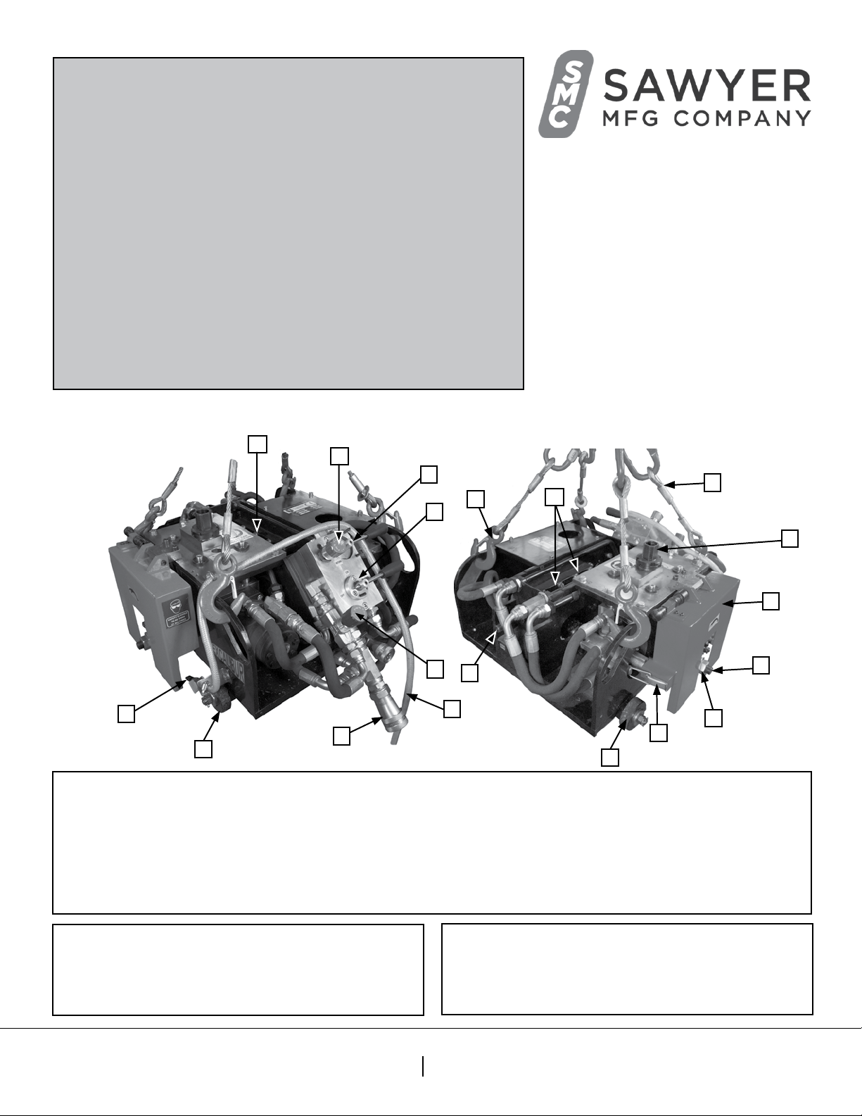
A. Using the two liing cables (F, Fig. 8), li the Excalibur onto the pipe.
B. Release the liing mechanism, ensuring the machine is sll supported on
the pipe unl the chain is ghtened and secured.
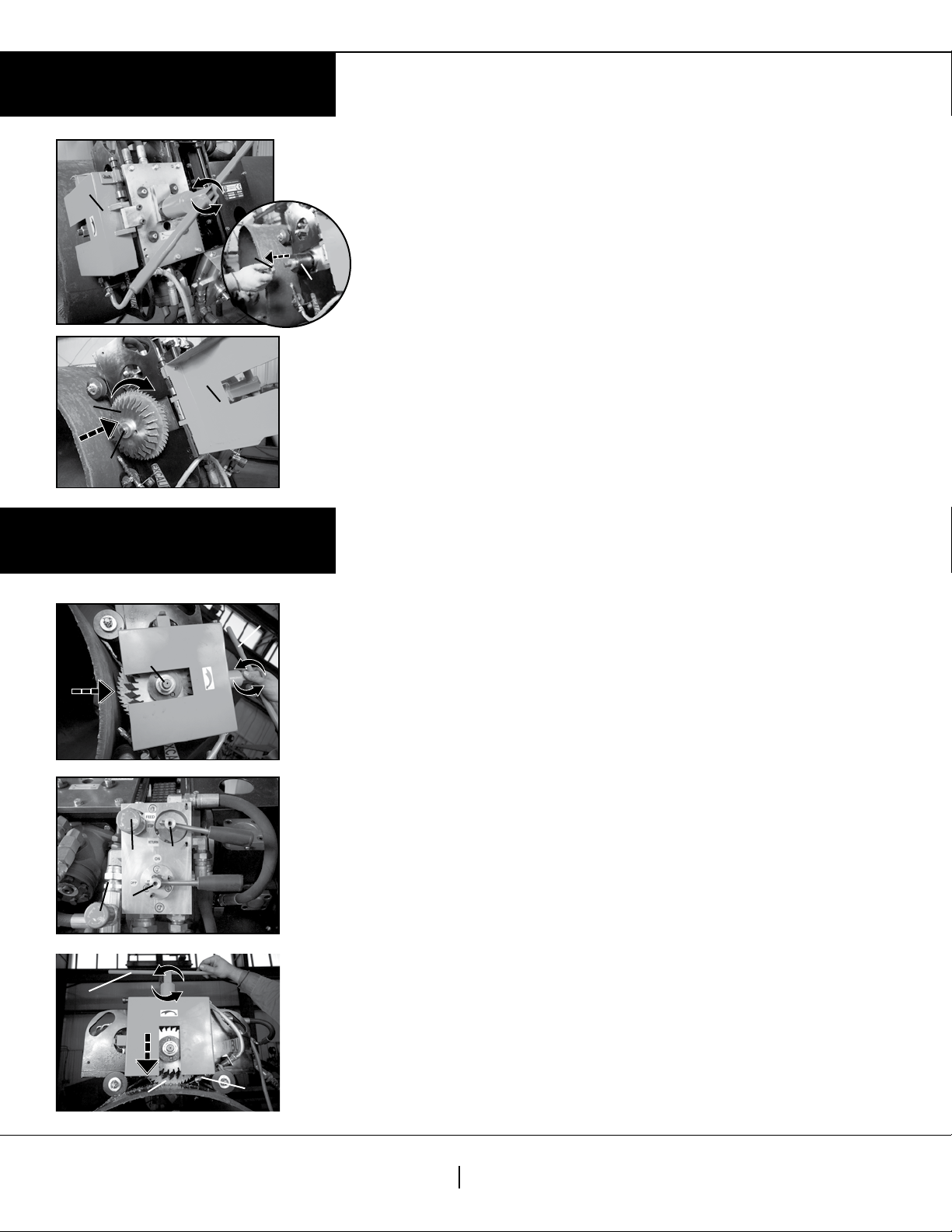
C.
Tighten the mesh chain by rotang the Chain Tensioning Screw
(W, Fig. 9)
counterclockwise with the 16 mm Swivel T Handle.
D. Torque the Chain Tensioning Screw (W) to 96 ./lb. (130NM).
1. Release the tension on the two Liing Cables (F) and unhook the Liing
Spring Clips (G) from the machine.
E.
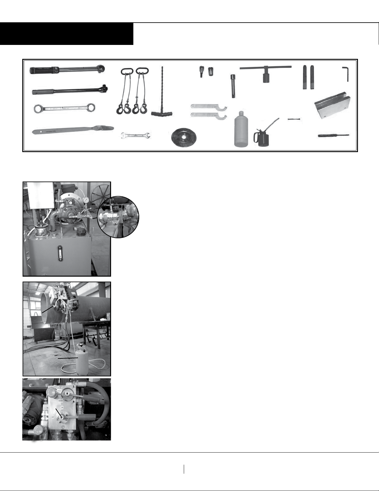
Connect the supplied air/hydraulic hoses to the relevant connectors on the
Excalibur machine, and start the power source
Hose Connector (T, Fig. 10) on the Excalibur, and start the power source.
1. Turn the Start/Stop Control to the ON posion. (B, Fig. 10a)
Note: Hydraulic Model only – If this is the rst me the hydraulic power supply is being run, let the
hydraulic uid circulate through the machine 15-20 minutes to remove air bubbles from the uid.
2. Move the Machine Direconal Control (C, Fig. 10a) to the forward posion.
3. Turn the Machine Speed Control (D, Fig. 10a) valve counter-clockwise.
4.
Rotate the Excalibur one full turn around the pipe to align the chain. (Fig. 11)
Note: Verify there is enough clearance for the machine to travel around the pipe.
5. Re-torque the Chain Tensioning Screw (W, Fig. 9) to 96 ./lb. (130NM).
6. Turn o the air/hydraulic power source.
Tip: Open pressure bypass valve before turning o power to the Excalibur.
Fig. 10
Fig. 5
Fig. 9
Fig. 6
Fig. 11
Installation
Fig. 7
X
T
Q
R
S
U
V
Fig. 8
Fig. 7a
F
Fig. 10a
D
C
B
X
W

Sawyer Manufacturing Company
7799 S. Regency Dr., Tulsa, OK 74131 USA
F918.834.0318
info@sawyermfg.com
P918.834.2550
sawyermfg.com
V1
Installation
Operation
Fig. 13
Fig. 14
Fig. 12
Fig. 13
Fig. 15
5. Installing Center and Beveling Cuers
A.
With the aid of the Blade Lowering/Raising Handle, turn the Feed Screw
(E, Fig. 9) clockwise unl the cuer spindle is raised to its highest posion.
B. Open the Blade Safety Cover (I, Fig. 12a) and loosen the Cuer Lock Nut (L)
by rotang it clockwise. Remove the Cuer Lock Nut, washer and Cuer
Support Collar (L).
Note: Remove all metal chips and debris from the wheel supports and slots in the boom of the chassis.
C. Place the Milling Cuer (M, Fig. 12a) on the Cuer Spindle (J) so the cung
edge is facing downward.
Note: All teeth must face clockwise, as indicated by the arrow on the Cuer Safety Cover
D. Align the holes in the Milling Cuer (M) with the two hardened pins and
push the Milling Cuer forward unl it contacts the face of the male
cuer drive collar. Follow the same procedure to install the center
Milling Cuer and the second Milling Cuer.
E. Install the Cuer Support Collar, washer and Cuer Lock Nut. (L, Fig. 13)
F. Lower the Cuer Safety Cover (I) and latch the Blade Safety Device
to the cover.
Note: The machine will not funcon if blade safety cover is not latched to the blade safety device.
1. Preparaon for the cung process
A. With the Blade Lowering/Raising Handle, (H, Fig. 13) turn the Feed
Screw (E) unl the Cuer Spindle (J) is raised to its highest posion.
B. Turn the Start/Stop Control (B, Fig. 14) to the O posion.
C. Turn the Machine Direconal Control (C, Fig. 14) to the Stop posion.
D. Turn the Machine Speed Control (D, Fig. 14) clockwise to the 0 or fully
closed posion.
E. Turn the Blade Speed control (A, Fig. 14) clockwise to the 0 or fully
closed posion.
Note: Ensure the safety cuer cover is closed and the blade shut-o device is latched to the cover.
F. Turn o the air/hydraulic power source and bleed the pressure from the
supply hoses.
G. Connect and secure the air/hydraulic hose quick disconnects to the
Excalibur.
Note: Air lter/lubricaon device must be placed in the center of the two air hoses. Make sure the
blow of the lubricator assembly is lled with pneumac oil.
H. Start the power supply.
I. Verify correct air/hydraulic output pressure and ow rate.
2. Using the Excalibur for the cung process
A. Turn the air valve of the Mist Lubricaon System device On.
B. Adjust the Lubricator Nozzle (N) as needed to provide a steady ow of
coolant on the blades.
C. With the Blade Lowering/Raising Handle, (H, Fig. 15) turn the Feed
Screw (E) counter-clockwise unl the Milling Cuers (M) are through the
thickness of the pipe at desired depth.
I
I
J
H
H
MN
J
B
ADC
M
Fig. 12a
L
E

Sawyer Manufacturing Company
7799 S. Regency Dr., Tulsa, OK 74131 USA
F918.834.0318
info@sawyermfg.com
P918.834.2550
sawyermfg.com
V1
Operation
Fig. 21
Fig. 20
Fig. 19
Fig. 17
D.
Remove the Blade Lowering/Raising Handle (H) from the Feed Screw (E)
E. Turn the Machine Direconal Control (C, Fig. 16) to the Feed posion.
Note: Never aempt to cut pipe by placing the forward control knob in the REVERSE posion.
F. Slowly open the Machine Speed Control (D, Fig. 16) unl the desired
forward (feed) speed is achieved.
Note: Check to see if the desired cut and bevel depth are being achieved.
G. Cut the pipe (Fig. 17), machine will travel full rotaon around the pipe.
H. Cuer stoppage
1. If a cuer block occurs, quickly turn the Machine Direconal Control
(C, Fig. 18) to the Return posion and leave it in that posion unl the cuers
start rotang.
2. When the cuers begin rotang, move the Machine Direconal Control
(C, Fig. 18a) to the Stop posion.
3. Close the Machine Speed Control (D, Fig 18) a small amount.
4. Turn the Machine Direconal Control (C, Fig. 16) to the Feed posion.
I. When the cut is complete, move the Machine Direconal Control
(C, Fig. 20) to the Stop posion.
1. Using the Blade Lowering/Raising Handle, (H, Fig. 21), rotate the Feed
Screw (E) unl the Milling Cuers (M) are raised to their highest posion.
2. Turn the Start/Stop Control (B, Fig. 20) to the O posion.
3.
Turn the air valve of the Mist Lubricaon System to the O posion.
4. Turn o the air/hydraulic power supply.
5. Bleed all air/hydraulic pressure from the hoses, and disconnect the hoses from
Hydraulic Hose Connector (T) on the Excalibur.
3. Disconnecng the power source
A. Hydraulic Machine
1. Turn o the hydraulic power supply.
2. Bleed all hydraulic pressure from the hoses by rotang the cuer control knob
back and forward to the OFF and ON posion several mes.
3. Disconnect the hydraulic hose from the Excalibur.
B. Pneumac Machine
1. Turn o air supply.
2. Bleed all air pressure from the hoses by rotang the cuer control knob back
and forward to the OFF and ON posion several mes.
3. Disconnect the air hose from the Excalibur.
C. Electric Machine
1. Turn o the power supply.
Fig. 16
Fig. 18
D
D
C
C
Fig. 18a
H
C
C
D

Roune Maintenance
Tip: Plan all roune maintenance when the machine is not in operaon.
When the machine is cung “heavy wall or high strength alloy pipes”, it
is recommended the machine be thoroughly checked aer each cut.
General
1. Inspect the Cuer Blades for wear and the integrity of
the edge aer each cut.
2. Check the Mist Lubricaon System on a regular basis
during the cung process. (if applicable)
A. Check nozzles for obstrucon aer each use.
Clean as necessary.
Note: Always keep the synthec coolant plasc bole clean to avoid debris
or dirt that may obstruct the Lubricaon Nozzle (M).
Pneumac Machine
1. Check the Air Filter / Lubricaon Device and periodically
check the assembly to be certain it is funconing properly
when using the Air Drive Excalibur.
A. Drain the water from the water separator of the Air Filter/
Lubricaon Device on a regular basis.
B. Replenish the oil in the inline Lubricator of the Air Filter/
Lubricaon Device with pneumac oil as needed.
Note: Periodically check the Air or Hydraulic Power Supply.
Hydraulic Machine
Tip: To obtain the best performance, it is important to use a hydraulic
uid with the best viscosity index for the ambient temperature in which
the machine will be working. Under extreme condions, use synthec
addive oil with a high degree of stability.
Note: for applicatons with vegetable biodegradable oil and special mixture,
contact Sawyer prior to use.
A. Filter hydraulic uid through a 25 micro lter when
adding oil to the Hydraulic Power Supply reservoir
Note: Failure to lter the uid may cause damage to the hydraulic blade
and forward motors. Use the same hydraulic oil that was originally in the
reservoir.
Maintenance
Lubricaon Guide
1. The following parts must be oiled once
weekly.
with Lubricang Oil Specicaon: ISA VG 68,
Viscosity 68 & Density 0.887
A. Upper and Lower Gibs
B. Chain Tension Screw.
C. Bronze Bushings.
D. Axle.
E. Depth Control Assembly.
2. The following part must be oiled every 2
weeks.
A. Bronze Wheel Bearing.
3. The following part must be oiled daily.
A. Guide Rod.
B. Install torch inside torch holder.
C. Tighten adjustment knob.
4. The Main Transmission Unit and the Feed
Transmission Unit must be greased using
Lithium based high melng point grease
aer every 10-15 hours of usage.
5. Regarding the chain, this must be inspected,
cleaned and oiled at least once every week.
Table 2. Posioning of the wheels for various pipe diameters and
cung depths
This manual suits for next models
3
Table of contents
Other Sawyer Cutter manuals
Popular Cutter manuals by other brands

ATIKA
ATIKA ST 250 Operating manual – safety instructions – spare parts

Marshalltown
Marshalltown VINYL RIPPER manual

EINHELL NEW GENERATION
EINHELL NEW GENERATION NRF 800L operating instructions

Koike Sanso Kogyo
Koike Sanso Kogyo AUTO PICLE-S Operation manual

Georg Fischer
Georg Fischer RA 21 operating instructions

W&T
W&T 81600 manual