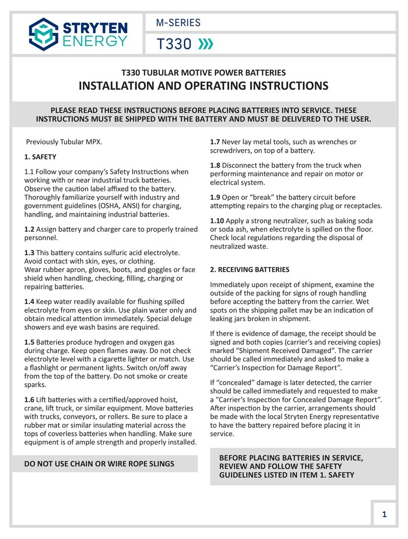
Stryten Energy M Series User manual

M-SERIES
1
Li510 LITHIUM-ION BATTERIES
SERVICE MANUAL
WARNINGS AND GENERAL INFORMATION
Observe these Instrucons and keep
them located near the baery for future
reference. Work on the baery should
only be carried out by qualied personnel.
While working on baeries wear
protecve eye-glasses
and clothing.
Cauon – parts of the baery may carry
dangerous voltages. Be careful when
handling cables.
Keep baery dry.
DO NOT smoke.
DO NOT dispose of the baeries in a re.
DO NOT dispose of the baery in
normal waste.
DO NOT include baery with lead acid
baery recycling.
Explosion and re hazard. Avoid short
circuits. Avoid electrostac charges and
discharges/sparks.
Keep children away from baeries.
DO NOT pressure wash.
- Lithium Baeries are heavy. Make sure
they are installed securely.
- Handle with care, avoid mechanical shock.
- Do not li or pull up on power or
communicaon cables.
- Avoid wearing any loose metallic items
such as jewelry, watches, or bracelets
- Corrosive contents! Do not open. Avoid
contact with contents of a damaged
baery.
- To avoid the release of harmful gases,
avoid deeply discharging, charging
when damaged, and improperly charging
the baery.
- Use cered insulated safety tools for
installaon. Any work procedures
and tools used should be in compliance to
EN 60900 or similar standard.
Baery may require recycling in
accordance with local laws. Contact Stryten
Energy or regulatory authories for further
informaon. DO NOT include baery with
lead acid baery recycling.
Tray liing at this area.
Li510
Previously LiFT FORCE LPX 2.0

2
M-SERIES
Do not break the warranty seals of any
baery without authorizaon from Stryten
Energy Service! Breaking a warranty seal
without authorizaon from Stryten Service
will void the warranty.
Stryten Energy Move Power Service 1-866-462-2288 strytenncc@stryten.com
Li510
Before working on any baery, a Stryten
Energy ServiceMAX cket must be created!
Contact Stryten Energy customer service if
you need assistance creang a ServiceMAX
cket.
TABLE OF CONTENTS
Baery System Diagram ................................................................................................................................................... 3
Major Components............................................................................................................................................................ 4
Idenfying Li510 Baery Informaon ............................................................................................................................ 4
Opus Baery Data Display ............................................................................................................................................... 5
Baery Power Switch LEDs .............................................................................................................................................. 6
Periodic Maintenance ....................................................................................................................................................... 7
Fully charging the baery ............................................................................................................................................. 7
Keeping power and aux contacts on charger connector clean ................................................................................. 7
Checking cable from baery to Forkli ...................................................................................................................... 8
General Operaonal Consideraons ........................................................................................................................... 8
Troubleshoong Issues During Baery Operaon ....................................................................................................... 8
SOC on Opus display does not match Forkli BDI display ......................................................................................... 8
Forkli goes into “turtle” mode at high or low SOC .................................................................................................. 9
Baery quickly drops to low state of charge aer charging ..................................................................................... 9
Baery beeps for 15 seconds and stops with Over Current CHG warning .............................................................. 9
Forkli will not operate – All zeros displayed on Opus display ............................................................................... 10
Forkli will not operate – All values displayed on Opus display are normal ......................................................... 10
Forkli will not operate – Low SOC Alert ................................................................................................................. 10
Troubleshoong Issues During Baery Charging ........................................................................................................ 11
Opus displays High temperature warning during charge ........................................................................................ 11
Troubleshoong M-Series X-3 and X-7 charger communicaon problems:........................................................... 11
Instrucons for downloading charger records from Stryten Energy M-Series X-3 and X-7 chargers.....................13
Service/repair of REMA320 and REMA640 Charger connectors ............................................................................... 15

3
M-SERIES
Li510 BATTERY SYSTEM DIAGRAM
Li510
M-Series
X-3 and X-7 1ph 24v 1ph 36v ELi

M-SERIES
4
MAJOR COMPONENTS
Components used by Operators, most commonly
serviced:
Charger Connector – Delivers power from charger.
DIN320 or DIN640, per current requirements. Uses aux
pins for communicaons with charger
Forkli cable and connector – Delivers power to
forkli, connector type per customer specicaon
Power Buon and Buzzer – Acvates baery, alert
operator of warnings as needed
Opus Display – Provides baery informaon to
Operator such as State of Charge (SOC) and other
status informaon
Components interior to the baery, not typically
serviced:
Power Modules – Congured in series and/or parallel
to achieve baery voltage and capacity per customer
requirements
BMS – Controls System operaon, Monitors Power
Modules
Power Contactors – Controlled by BMS. Used to
Isolate truck while charging and as needed for system
safety events
Charger and Forkli Fuses – Protect against system
overcurrent
Baery Tray – Protects components and provides
ballast for forkli
Power Bus – Power distribuon to and from individual
Power Modules
CANbus and Safety Line – Between BMS and all
modules.
IDENTIFYING Li510 BATTERY
INFORMATION
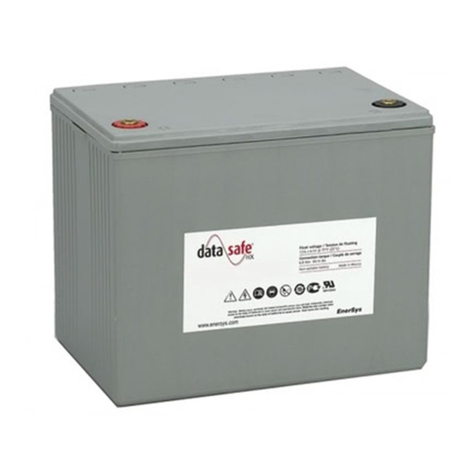
Every Li510 baery has a label plate on the lid of
the baery which idenes the following baery
informaon:
• Nominal Voltage
• Max Charge Voltage
• Capacity in Ahrs
• Energy in kWh
• Weight, in kg and lbs
• Model number
• Serial Number
Before servicing a Li510 baery, make sure to note
the model and serial number of the baery, in the
event that this informaon needs to be provided to
Stryten Energy Service. (See below)
Li510

M-SERIES
5
Li510
OPUS BATTERY DATA DISPLAY
The Opus Display shows State of Charge (SOC), baery
temperature, voltage and current. The display is used
primarily by the Operator to monitor SOC in between
charging breaks. (See below)
If the BMS detects a warning or alarm condion, it will
show the warning or alarm on the display. (See below)
For warnings, the buzzer will beep once per second.
Otherwise, the baery operates as normal. For alarm
condions, the buzzer beeps 3 mes per second for
15 seconds, to alert the operator that the baery will
shut o and forkli operaon will be disabled in 15
seconds.
Once the alarm condion is removed, the baery
can be restarted with the power/reset buon. When
troubleshoong a Li510 baery, be sure to note the
values displayed on the Opus screen before, during
and aer baery problems occur.
The following Warnings, Alarms and Alerts
may be displayed on the Opus during normal
operaon:
Low SOC Warning – typically the most common
warning, indicang that the baery needs to be
charged soon
Low SOC Alert – If the Baery reaches 0% SOC, the
baery will shut itself o in order to protect itself.
The buzzer beeps 3 mes per second for 15 seconds,
to alert the operator that the baery will shut o and
forkli operaon will be disabled in 15 seconds. If a
baery shuts o with a low SOC Alert, it can be reset
one me, aer which the forkli must immediately
return to the charging area so that the baery can be
charged
Low Voltage Alarm – If following a Low SOC Alert, the
baery is not immediately charged and connues to
be used, the baery will further protect itself with
a Low Voltage Alarm. Aer the Low Voltage Alarm
occurs, the baery cannot be reset and the forkli
must be towed back to the charging area
Low Voltage Warning – If the baery is at low SOC
and the forkli is performing work that puts a heavy
power load on the baery, a Low Voltage Warning
may occur. This is another indicaon that the baery
needs to be charged.
High or Low Temperature Warning – If the baery
gets within 5C of its high or low temperature limits, a
warning will be displayed on the Opus
High or Low Temperature Alarm – If the baery
exceeds its high or low temperature limits, an alarm
will be displayed on the Opus. The buzzer will beep
rapidly for 15 seconds, aer which the baery will
shut down for protecon.
The following Warnings, Alarms and Alerts
may be displayed on the Opus during error
condions:
Please Check CAN Communicaon – If this alarm
occurs during charging, it is typically indicave of
a communicaon error between the charger and
baery. This alarm is usually resolved by servicing
of the AUX pins on the charger connector on the
baery and / or the Aux pins on the charger’s
output connector. If this error occurs during forkli
operaon, with no charger present, it may
indicate a CAN communicaon error inside

M-SERIES
6
Li510
On / O buon LED Green LED Red
System in Standby mode O O
System acve, no alarm or warning detected Once per second O
Warning O Once per second
Alarms O Three per second
Buon pressed for less than 5s to Reset
Warnings / Alarms On as long as buon is pressed O
Buon pressed for more than 5s to move
from acve to Standby mode O On as long as buon is pressed
Buon is pressed in standby mode and the system
is moved into acve mode On as long as buon is pressed O
the baery, in which case contact Stryten Energy
Service to arrange for factory repair.
Over Current CHG Alert – This Alert is typically
indicave of a loose current shunt in one of the
power modules. It typically occurs when the forkli is
operang, and results in the baery powering down
aer issuing an alarm beep for 15 seconds. In some
cases the problem may stop aer the baery is reset,
however this issue, once presented, usually reoccurs
with increasing frequency. If this message occurs,
contact Styrten Energy Service to arrange for factory
repair.
Plug Removed DIS Alert – This Alert is typically
indicave of a loose current shunt in one of the power
modules. It typically occurs when the baery is put
on charge, and results in the baery powering down
aer issuing an alarm beep for 15 seconds. In some
cases the problem may stop aer the baery is reset,
however this issue, once presented, usually reoccurs
with increasing frequency. If this message occurs,
contact Stryten Energy Service to arrange for factory
repair.
Safety line Alert – This Alert indicates that either one
of the Power Modules has detected a problem or that
one of the internal CAN communicaon lines is loose.
If this message occurs, contact Stryten Energy Service
to arrange for factory repair.
Plausibility Error – The BMS has detected inconsistent
readings between Power Modules in the baery. This
may indicate that a module has a blown fuse, a low
voltage cell block, or some other unusual condion. If
this message occurs, contact Stryten Energy Service to
arrange for factory repair.
BATTERY POWER SWITCH LEDs
The Li510 Baery power/reset switch has two LEDs
that are also used to indicate status of the baery.
The power / reset switch is located on the gland pod,
on top of the baery, on the same side of the gland
pod as the buzzer.
To power the baery on, press and hold the Power/
Reset buon unl it turns green (aprox 1s). To power
the baery o, press and hold the Power/Reset buon
unl it turns red (aprox 5s). When troubleshoong a
baery, make sure to note the status of the switch
LEDs (See below)

M-SERIES
7
Li510
PERIODIC MAINTENANCE
Fully charging the baery
In order to keep all the cells in the baery balanced, it
should be fully charged to 100% State of Charge (SOC) at
least once per week and ideally once per day, as shown
on the M-Series X-3 and X-7 charger screen below.
12
LiFTFORCE 2.0 Service manual
Confidential material of Stryten Energy
Periodic Maintenance
Fully charging the battery
In order to keep all the cells in the battery balanced, it should be fully charge to 100% State of Charge
(SOC) at least once per week and ideally once per day, as shown on the Fury charger screen below
In order to make sure that the battery is fully charged, plug the battery into the charger and do not
disconnect the battery until the “Complete” status is shown on the charger. Make sure that the weekly
charging schedule allows adequate time for the battery to get a full charge once per week and ideally
once per day
In order to make sure that the baery is fully
charged, plug the baery into the charger and do not
disconnect the baery unl the “Complete” status
is shown on the charger. Make sure that the weekly
charging schedule allows adequate me for the
baery to get a full charge once per week and ideally
once per day.
Keeping power and aux contacts on charger
connector clean
Make sure that the blue coding key is installed
properly and that the interior mang surfaces of the
2 power pins and 4 aux pins on the charger connector
are clean. Clean the interior of the pins with either
95% ethanol or 91% isopropyl alcohol and swabs.
This should be done at least every six months in a
clean facility and more oen for facilies with large
amounts of airborne material.
13
LiFTFORCE 2.0 Service manual
Confidential material of Stryten Energy
Keeping power and aux contacts on charger connector clean
Make sure that the blue coding key is installed properly and that the interior mating surfaces of the 2
power pins and 4 aux pins on the charger contactor are clean. Clean the interior of the pins with either
95% ethanol or 91% isopropyl alcohol and swabs. This should be done at least every six months in a
clean facility and more often for facilities with large amount of airborne material
REMA640 Charger connector contacts
REMA320 Charger connector contacts
REMA640 Charger connector contacts
REMA320 Charger connector contacts
13
LiFTFORCE 2.0 Service manual
Confidential material of Stryten Energy
Keeping power and aux contacts on charger connector clean
Make sure that the blue coding key is installed properly and that the interior mating surfaces of the 2
power pins and 4 aux pins on the charger contactor are clean. Clean the interior of the pins with either
95% ethanol or 91% isopropyl alcohol and swabs. This should be done at least every six months in a
clean facility and more often for facilities with large amount of airborne material
REMA640 Charger connector contacts
REMA320 Charger connector contacts
When the blue coding key is inserted properly, the
baery voltage will be visible through the hole in the
top of the connector. See the secon on servicing the
charger connector if the coding key is not installed
properly.
14
LiFTFORCE 2.0 Service manual
Confidential material of Stryten Energy
When the blue coding key is inserted properly, the battery voltage will be visible through the hole in the
top of the connector. See the section on servicing the charger connector if the coding key is not installed
properly.

M-SERIES
8
Li510
Checking cable from baery to Forkli
Check the connector to the forkli to make sure that
it is inserted ghtly. Also check the exit point of the
baery compartment to make sure that the power
cables to the forkli are not rubbing on any metal
surface where they could be abraded.
15
LiFTFORCE 2.0 Service manual
Confidential material of Stryten Energy
Checking cable from battery to Forklift
Check the connector to the forklift to make sure that it is inserted tightly. Also check the exit point of the
battery compartment to make sure that the power cables to the forklift are not rubbing on any metal
surface where they could be abraded
General operaonal consideraons
Make sure that the baery is kept clean and dry
• Never clean the system or system parts using a
vapor jet or spray water.
• Dirt and water may enter the system and cause
major damage.
• Use only a moist and clean coon cloth for cleaning.
• Avoid chlorine-based disinfectant wipe-downs.
Do not let the baery sit for long periods of me at
low state of charge.
Before being placed in storage the baery should be
charged to 50 % SOC, powered o, and disconnected
from both the vehicle and the charger.
The Li510 Lithium Material Handling Baery system
has a very low self-discharge and can be put into
storage for up to 12 months. It must then be
recharged
If baeries are taken out of service, they should be
stored in a dry and frost free room.
TROUBLESHOOTING ISSUES DURING
BATTERY OPERATION
SOC on Opus display does not match Forkli
BDI display
The Li510 baeries use NMC chemistry. If the Forkli
Baery Discharge Indicator (BDI) is congured for
lead acid or some other type of lithium chemistry,
the SOC displayed by the Opus may not match the
SOC displayed by the forkli BDI. For example, in the
images below, the Opus display on the top is showing
100% SOC and the forkli BDI on the boom is
showing 90% SOC.

M-SERIES
9
Li510
The discrepancy on the previous page in displayed SOC
values is normal when the truck BDI is congured for
lead acid or some other lithium chemistry. Check with
the forkli dealer and/or forkli technical support
to congure the truck BDI for NMC lithium. If this is
not possible, use the SOC displayed by the Opus to
gauge the baery SOC and ignore the SOC displayed
on the forkli BDI. The following table should be used
when seng up a Forkli BDI to be used with Li510
baeries.
Nominal
Voltage
0% SOC 100%
SOC
Undervoltage
alarm
Overvoltage
alarm
24V 22.4 V 28.8 V 20.3 V 29.8 V
36V 32.0 V 41.2 V 29.0 V 42.5 V
48V 44.8 V 57.7 V 40.6 V 59.5 V
72V 64.0 V 82.4 V 58.0 V 85.0 V
80V 67.2 V 86.5 V 60.9 V 89.3 V
96V 89.6 V 115.4 V 81.2 V 119.0 V
Forkli goes into “turtle” mode at high or low SOC
If the Forkli BDI is congured for lead acid or some
other type of lithium chemistry, the Forkli BDI may
limit the operaon at either the high voltage or low
limit of the baery. In this case, it will be necessary
to work the forkli dealer and/or forkli technical
support to congure the truck BDI for NMC lithium.
Use the table on the previous page to verify that the
working voltage range of the baery is supported by
the Forkli’s drive electronics and set the Forkli’s
BDI accordingly.
Baery quickly drops to low state of charge aer
charging
If the baery quickly drops to a low state of charge
aer charging, this may be a sign of a loose current
sensor inside the baery. Indicaons that the Low SOC
Warning is likely due to a loose current shunt are:
1. Typically the voltage reading will be higher than
normal for a low SOC baery. For a 36v baery, the
voltage that corresponds to 6% SOC is approximately
34V. If the baery voltage shown at low SOC is
signicantly higher than this, it could indicate a loose
current sensor.
2. If a current shunt is loose, typically there will be
a current of ~-65A displayed, even if the forkli is
staonary and not moving.
While the forkli can be operated safely at a false low
SOC, the warning beeping from the baery may be
objeconable to operators. If this error occurs, please
take a picture of the Opus display and baery serial
number, and contact Stryten Energy Customer service,
as this is not a eld repairable issue.
Baery beeps for 15 seconds and stops with Over
Current CHG warning
This error indicates a faulty current sensor internal to
the baery. Typically a current of ~70A is displayed,
even though the baery is not on charge. If this error
occurs, please take a picture of the Opus display and
baery serial number, and contact Stryten Energy
Customer service, as this is not a eld repairable issue.

M-SERIES
10
Li510
Forkli will not operate – All zeros displayed on
Opus display
This indicates that there is an internal CAN
communicaon problem within the baery. If this
error occurs, please take a picture of the Opus display
and baery serial number, and contact Stryten Energy
Customer service, as this is generally not a eld
repairable issue.
Forkli will not operate – All values displayed on
Opus display are normal
If the forkli does not operate and the Opus display
does not indicate any problems, the rst thing to
check is to conrm that the forkli cable from the
baery is mated properly to the connector on the
forkli.
If there are no obvious problems with the connecon
from the baery to the forkli, disconnect the
baery from the forkli and measure the voltage
on the baery terminals. If the baery is in normal
operang mode (LED on the power switch is slowly
ashing green) and the baery is not being charged,
the baery voltage should be present at the output
terminals of the baery. If baery voltage is present,
the problem is likely with the forkli. Contact the
forkli dealer and/or forkli technical service for
further support.
If there is no voltage on the baery’s output cable
when the baery is powered on, not charging and
disconnected from the forkli, it will be necessary
to open the baery for further troubleshoong.
Contact Stryten Energy Customer service to open
a ServiceMAX cket before proceeding. Make sure
to provide pictures of the Opus display and baery
serial number, voltage readings and any pernent
informaon about how and when the forkli stopped
working.
The forkli output cables are fused, so the next step
aer receiving authorizaon from Stryten Energy
is to check the connuity of the fuse on the forkli
cable. If the fuse is not open, the next thing to check
is the contactor for the forkli cable. All baeries
have a contactor on the posive cable and some
modules have a contactor on the negave cable as
well. Contact Stryten Energy customer service for
assistance troubleshoong the contactors if the
problem appears to be with the contactors.
Forkli will not operate – Low SOC Alert
If the SOC of the baery drops below 10%, the baery
will beep once per second and a low voltage
warning will be shown on the Opus display

M-SERIES
11
Li510
If the SOC drops to 0%, the baery will beep rapidly
for 15 seconds and turn o. The reset buon can be
pressed once to get the vehicle to the charger. Aer
that, the baery remains turned o in order to avoid
further damage. The vehicle now has to be towed to
the charge with auxiliary means.
TROUBLESHOOTING ISSUES DURING
BATTERY CHARGING
Opus displays High temperature warning
during charge
If a baery is being charged at close to its temperature
limits, the baery will display a warning. The warning
occurs when charging temperature reaches 45C or
drops to 5C.
The M-Series X-3 and X-7 chargers will never charge
a Li510 baery above or below its allowable charge
temperature limits. When the baery reaches 45C, the
M-Series X-3 and X-7 chargers will reduce its output
current to slow the rate of heang. If the baery ever
reaches 50C, the M-Series X-3 and X-7 chargers will
stop charging and wait for the baery to cool before
resuming charging.
In addion to displaying a warning, baeries with
BMS rmware versions prior to 2.8.7 will emit a
slow warning beep (once per second) if the charging
temperature exceeds 45C or drops below 5C. This
beeping is intended as a warning only, as the baery
is sll operang within its safe limits and can sll
safely charge. However this beeping has caused some
confusion with customers, as beeping during charging
is disconcerng to operators. This has caused some
operators to stop the charger at 45C when the baery
starts to beep, even though the baery is sll well
within its allowable charge temperature.
Beginning with BMS rmware version 2.8.7, Li510 will
no longer beep when they reach 45C while charging
on a M-Series X-3 and X-7 charger. Because the
M-Series X-3 and X-7 chargers will never allow the
baery to reach 50C or drop to 0C, there is no need
to warn the user as these limits are approached.
Customers with BMS rmware prior to 2.8.7 may
contact Stryten Energy service to schedule a rmware
update if desired. Customers with older rmware
should be aware that if the baery is charging at
temperatures between 45C and 49C, a slow beep
of once per second is normal, and not a cause for
concern.
Troubleshoong M-Series X-3 and X-7 chargers
communicaon problems:
If any errors are encountered while charging a Li510
baery, the M-Series X-3 and X-7 chargers will stop
and display an error message.
If an error occurs while charging, hit the down buon
(V) to the right of the display and check the Error
Details for addional informaon. Take a picture of
the main charger screen and Error Details screen in
case assistance is needed from Stryten Energy service.

M-SERIES
12
Li510
If there is a connecon problem with the baery, one
of several errors may be displayed.
1) “No CANbus communicaon” Error
2) “Lost communicaon with baery” Error
3) “BMS reported not ready to charge” Error
Whenever an error occurs during charging, the
rst troubleshoong step is to determine if the
problem is with the baery or charger.
a. Check the baery with other chargers i. If the
baery fails on other chargers, it is a baery problem
ii. If the baery works on other chargers, it is problem
with the original charger.
b. check the charger with other baeries i. If the
charger works with other baeries, it is a baery
problem ii. If the charger does not work with any
baeries, it is problem with charger.
If problem is with the baery connecon
Check to make sure that the pins on the baery and
charger are clean so that they will make good contact.
Check to make sure that none of the pins are loose.
Next, check the Aux pins with a mulmeter
The AUX pin connecons for a REMA320 charger
connector are shown below:

M-SERIES
13
Li510
The AUX pin connecons for a REMA640 charger
connector are shown below:
For both REMA320 and REMA640 charger connectors,
the boom two pins on the connector are the CAN
bus communicaons lines.
When the Opus display is aached the resistance
between these two pins should read ~60 ohms. When
the Opus is disconnected, they should read ~120
ohms.
For REMA320 connectors, the two top pins are the
safety line pins.
For REMA640 connectors, the two middle pins are the
safety line pins.
There should be 5v between the + on the le and the -
on the right.
If the readings are not as shown above, the aux pins
will need to be repaired.
INSTRUCTIONS FOR D0WNLOADING
CHARGER RECORDS FROM STRYTEN
ENERGY FURY CHARGERS
1) Obtain a Stryten Energy USB sck from your Stryten
Energy Service Authorized Representave.
2) Insert the USB sck into the USB port of the
charger.
3) While the charger is wring logs to the USB sck,
a message will be displayed on the M-Series X-3 and
X-7 chargers. Do not remove the USB sck while
the charger is wring log les. This will take about a
minute.

M-SERIES
14
Li510
4) When the charger has nished wring its log les, it
will display a message to say that it has completed the
transfer and that the USB sck can now be removed.
5) If you have mulple chargers, you can download
charger records from all of the chargers using the
same USB sck
6) Once you have downloaded all of the logs from
your chargers, you can send the USB sck back to your
Stryten Energy Service Authorized Representave for
analysis. Or to save me, you can email the les.
In the USB sck directory, go to the aw-chargers ->
in-box directory. Under that directory will be a folder
for each charger, named with the serial number of the
charger. In each charger folder, there will be a zip le
with the logs from that charger. Email each of these
zip les to your Stryten Energy Service Authorized
Representave.
The USB sck can be re-used to download charger
records mulple mes. Each me that records are
downloaded from a charger, a new zip ll will be
added to the folder for that charger. The number
aer the dash in the zip le name is the date and
me that the log was created. In the example above,
the logs for charger serial number 1826000029
were downloaded twice. The second zip le was
downloaded on April 8, 2021 at 12:42:16, so it is
the most recent of the two les. When sending
les to your Stryten Energy Service Authorized
Representave for analysis, you only need to send to
send the most recent les.
7) Please contact your Stryten Energy Service
Representave or email strytenncc@stryten.com for
addional help.

M-SERIES
15
Li510
SERVICE/REPAIR OF REMA320 AND
REMA640 CHARGER CONNECT0RS
Note – the procedure below shows a REMA320
connector. Servicing and repair of a REMA640
charger connector is idencal to the REMA320,
except that there is an unused third pair of aux
contacts, which is the top pair of contacts.
1) Check posion of baery voltage key. Take picture
of connector from front in order to verify that the
connector is replaced in the correct posion aer the
connector is serviced. (note – the picture below is
from a 36v baery. Other voltages will have the key in
a dierent posion).
2) Remove the power cable clamp and strain relief
cable es. (See below and top right)
3) Remove the voltage key. This is done from the back
of the connector. Using a needle nose pliers, gently
squeeze together the clips on the end of the key that
hold the key into place. Push slightly and the key will
come out from the front of the connector.

M-SERIES
16
Li510
4) Gently open the lid of the connector, using a small
screwdriver inserted into the hole le by the voltage
key to li up the lid.
5) Back the pins out of the connector housing and
service/repair/replace as needed.
If the exisng pins or harness are too damaged for
eld repair, replacement harnesses can be ordered
from Stryten Energy. The length of the harness will
vary depending on the baery model. Contact your
Stryten Energy service representave to determine
the correct part number to order for your baery
model. Make sure to give them the baery serial
number and model number.
6) Replace Power and Aux pins
The posive power pin (power cable with red jacket)
goes to the locaon marked + on the housing.
The negave power pin (power cable with black
jacket) goes to the locaon marked – on the housing.
The safety loop 5v pin (on red aux wire) goes to the
top aux pin posion of the REMA320 (middle posion
for REMA640), on the side closest to the negave
(black) power lead.
The safety loop Gnd pin (on black aux wire) goes to
the top aux pin posion of the REMA320 (middle
posion for REMA640), on the side closest to the
posive (red) power lead.
Both the CAN pins (on blue and white aux wires)
go into the boom set of aux pins, using a “pilot
adaptor”, which must be installed with the notch in
the adaptor facing up.
CAN high pin (on white aux wire) goes on the side
closest to the posive (red) power lead.
CAN low pin (on blue aux wire) goes on the side
closest to the negave (black) power lead.
Baery REMA Pinout

M-SERIES
17
Li510
7) Replace lid to the connector, making sure that the
aux pins are all fully inserted, so that the notches in
the pins all line up.
8) Before replacing the voltage key, make sure that all
pins are fully inserted in the housing. If any pins are
not all the way forward, repeat step 8.
9) Replace clamp to hold the power cables to the
connector, making sure not to pinch the aux comm
cable.
10) Use double zip es for strain relief, so that the
aux cable cannot get snagged and pulled from the
connector. Make sure that there is enough play in the
aux cable for the cable and connector to move from
side to side without pung strain on the aux cable.
Tighten the zip es so that the cut ends are towards
the interior of the cables
©2023 Stryten Energy Alpharea, GA 30005 SE1021 1/23
STRYTEN ENERGY
USA/PR 877.462.4636 CAN 800.268.2698 MEX +52 5543527927
Other manuals for M Series
5
This manual suits for next models
1
Table of contents
Other Stryten Energy Camera Accessories manuals
