STS DPC01-R500 User manual


1 Operating Instructions: DPC01-R500
Section I –Correct Use and Application ............................................................................................2
General ................................................................................................................................................................................2
Foreseeable Misuse of the Unit........................................................................................................................................... 2
Approved Application Conditions.....................................................................................................................................2
Proprietor Responsibilities ....................................................................................................................................................3
Adding Attachments and/or Accessories......................................................................................................................... 3
Safety Regulations for the Operation of the Unit ..............................................................................................................3
Consumables and Parts...................................................................................................................................................... 5
Ex Certified Units (if applicable) .........................................................................................................................................5
Lifting the Unit ......................................................................................................................................................................6
Unit Overview.......................................................................................................................................................................7
Section II –Unit Description .................................................................................................................8
Section III –Unit Operation .................................................................................................................. 9
Pre-start Inspections ............................................................................................................................................................9
Charging Operation.......................................................................................................................................................... 10
Unit Controls.......................................................................................................................................................................10
Moving the Unit..................................................................................................................................................................12
Operating the Lift and Lower Functions .......................................................................................................................... 13
Clamping a Drum.............................................................................................................................................................. 14
Section IV –Unit Maintenance, Troubleshooting and Consumables ...........................................15
Maintenance Checklist..................................................................................................................................................... 15
Troubleshooting ................................................................................................................................................................. 17
Consumables..................................................................................................................................................................... 19
Oil Replacement........................................................................................................................................................... 19
Polycarbonate Guarding Replacement .................................................................................................................... 20
Battery Replacement ................................................................................................................................................... 21
Safety Regulations Governing the Handling of Lead-Acid Batteries........................................................................ 22
Battery Charging Safety............................................................................................................................................... 23
Section V - Technical Specification.................................................................................................. 24
General Arrangement ...................................................................................................................................................... 24
Section VI - Decommissioning the Unit ............................................................................................25
Prior to Decommissioning.................................................................................................................................................. 25
Final Decommissioning and Disposal ............................................................................................................................... 25
Recommissioning............................................................................................................................................................... 25
Safety Tests to be Performed at Intervals and After Unusual Incidents. ........................................................................ 25

2 Operating Instructions: DPC01-R500
Section I –Correct Use and Application
Only operation manuals written in English are the original instructions, versions provided
in any other language then become a translation of the original instructions.
General
The unit described in the present operating instructions must be used, operated and
serviced in accordance with the present instructions. Any other type of use is beyond
the scope of application and can result in damage or injury to personnel, the unit or
property. The unit described in the present operating instructions complies with all
relevant directives and standards.
Foreseeable Misuse of the Unit
Personnel must take care when operating the unit. The following actions must be
adhered to:
•The maximum safe working load (SWL) must not be exceeded.
•Do not travel with a raised load 500mm above the ground unless necessary.
•When manoeuvring the unit, do not exceed a speed of 1m/s (3.6km/h).
•When manoeuvring a raised load above 500mm, do not exceed a speed of
0.1m/s (0.36km/h).
•If applicable, do not over lower the head of the unit onto a platform, such as
a mezzanine floor.
•Do not carry or lift other personnel.
•Do not stand or ride on the unit.
•Loads must be undamaged.
•Do not negotiate inclines unless otherwise stated.
•Do not stand underneath a raised load or within the confines of the unit
during operation.
•The load must be lifted and/or mixed by the attachment provided.
•Do not alter the unit specification from original supply.
•Do not disable, remove or adjust safety mechanisms or switches .
•Observe all instruction decals applied to the unit.
•Do not leave the unit in direct sunlight.
•The manufacturer shall not be held liable in case of faults or accidents due to
negligence, incapacity, installation by unqualified personnel or improper use.
Approved Application Conditions
•Operation in dry industrial and commercial environments.
•Permissible temperature range 5°C to 40°C.
•Lighting of at least 300 Lux.
•Altitudes not exceeding 2000m.
•Operation only on secure, level surfaces with sufficient capacity.
•Operation only on routes that are visible and approved by the proprietor .
•Operation in accordance with guidance stated within the operating
instructions.
•The unit must be maintained in accordance with the maintenance schedule
stated within the operating instructions.
•Appropriate personal protective equipment, PPE, must be worn at all times.

3 Operating Instructions: DPC01-R500
Proprietor Responsibilities
For the purposes of the present operating instructions the “proprietor” is defined as any
natural or legal person who either uses the unit themselves, or on whose behalf it is used.
In special cases (e.g. leasing or renting) the proprietor is considered the person who, in
accordance with existing contractual agreements between the owner and user of the
unit, is charged with operational duties. The proprietor must ensure that the unit is used
only for the purpose for which it is intended and that there is no danger to life or limb of
the user and third parties. Furthermore, accident prevention regulations, safety
regulations and operating, maintenance and repair guidelines must be followed. The
proprietor must ensure that all users have read and understood these operating
instructions. The proprietor must perform an onsite risk assessment before the unit is put in
to service.
IMPORTANT
Failure to comply with the operating instructions shall invalidate the warranty. The same
applies if improper work is carried out on the unit by the proprietor or third parties
without the permission of the manufacturer.
Adding Attachments and/or Accessories
The mounting or installation of additional equipment which affects or enhances the
performance of the unit requires written permission of the manufacturer. Local authority
approval may also need to be obtained. Local authority approval does not however
constitute the manufacturer’s approval. An onsite risk assessment must then be carried
out.
WARNING - ANY UNAUTHORISED MODIFICATIONS OR ADDITIONS TO THE UNIT SHALL
INVALIDATE THE WARRANTY AND STS SHALL NOT BE LIABLE.
Safety Regulations for the Operation of the Unit
Operator authorisation
The unit may only be used by suitably trained personnel, who have demonstrated to the
proprietor, or their representative that they can operate the unit safely and in
accordance with the operating instructions.
Operator’s rights, obligations and responsibilities
The operator must be informed of their duties and responsibilities and be instructed in
the operation of the unit and shall be familiar with the operating instructions. Operators
must be provided the appropriate PPE as mentioned in the ‘Approved Application
Conditions’ section of this manual.
Unauthorised use of unit
The operator is responsible for the unit during the time it is in use. The operator must
prevent unauthorised persons from operating the unit.
Damage and faults
The proprietor must be immediately informed of any damage or faults to the unit or
attachment. Units which are unsafe for operation must be quarantined until faults have
been rectified and the unit deemed safe for operation.

4 Operating Instructions: DPC01-R500
Servicing and repairs
All unit parts and consumables are available from STS. The unit must be fitted with
original STS parts and consumables unless otherwise stated. Any deviation from non-
original parts and consumables may result in injury to personnel or damage to the unit
and will invalidate the warranty. The operator must never disable, remove or adjust
safety mechanisms or switches. The unit should only be serviced and repaired by a
competent individual as selected by the company the equipment is intended for use
with.
Safety devices and warning decals
Safety devices, warning decals and warning instructions in the operating instructions
and on the unit must be strictly observed.
Travel routes and operational areas
Only use lanes and routes specifically designated for unit traffic. Unauthorised third
parties must stay away from operational areas. The unit must only be operated in
operational areas with sufficient lighting to avoid damage or injury to personnel, the unit
or property. Additional equipment is necessary to operate the unit in areas of insufficient
lighting.
Hazardous area of the unit
The hazardous area is defined as the area in which a person is at risk due to the unit itself
or movement of the unit and/or load. This also includes areas which can be reached by
falling loads. The operator must:
•Instruct unauthorised personnel to leave the hazardous area.
•Give a warning signal with plenty of time for personnel to leave.
•Stop all operations if unauthorised personnel are within or enter the hazardous
area.
Travel conduct
The operator must adapt the travel speed to local conditions. The unit must be driven at
slow speed when negotiating bends or narrow passageways, when passing through
swing doors and at blind spots. Abrupt stopping (except in emergencies), rapid U turns
and overtaking at dangerous or blind spots are not permitted. When not in use, the
equipment should be parked in a safe location with the brakes engaged.
Travel visibility
The operator must look in the direction of travel and must always have a clear view of
the route ahead. When transporting loads that affect visibility, a second person must
safely assist the operator to observe the travel route.
Type of loads
The operator must make sure that the load is in a satisfactory condition. Loads must
always be positioned safely and carefully. Use suitable precautions to prevent parts of
the load and/or their contents from falling or spilling.
Cleaning
Cleaning of the unit depends on the environment that the unit is used in. It is
recommended that the unit be cleaned daily if the unit comes into contact with
aggressive substances such as chemicals, fertilizers, salt, etc. It is recommended to use
detergent and a damp cloth to clean the body of the unit. Do not use flammable liquids
to clean the unit. Do not clean the unit with pressurised water. If the unit is rated for Ex
environments, the unit must be kept clean and dust free.

5 Operating Instructions: DPC01-R500
Personal protective equipment (PPE)
PPE must be worn at all times. A minimum of safety shoes must be worn while operating
the unit. Safety shoes, safety glasses, protective gloves, hearing protection and
protective overalls are to be worn when carrying out servicing, repairs and
maintenance. When operating overhead loads, a hard hat must be worn. End user
health and safety procedures and best practices should be followed in addition to the
above recommendations.
Consumables and Parts
Environmental hazards
Parts and oils must be disposed of in accordance with the relevant environmental
protection regulations.
Hydraulic hoses (if applicable)
Brittle hydraulic hose lines cause accidents. Hairline cracks in the hydraulic lines can
cause injury and infection. The hydraulic hoses should only be serviced or replaced by a
competent individual as selected by the company the equipment is intended for use
with. It is the responsibility of the proprietor to maintain the hydraulic hoses.
Lift chains (if applicable)
Incorrectly cleaned chains can cause accidents. Lift chains are safety-critical parts.
They must not contain any serious contamination. Lift chains and pivot pins must always
be clean. Never clean chains with high pressure steam jet cleaners, cold or chemical
cleaning agents. It is recommended to clean the chains and pivot pins in an unloaded
state with a citrus cleaner to remove dirt and grime followed by the application of a
PTFE based industrial grade chain lubrication spray or food grade lubrication spr ay.
NOTE: For more consumable information refer to ‘Section IV – Unit Maintenance,
Troubleshooting and Consumables’.
Ex Certified Units (if applicable)
Operational hazards
Processing of liquids or suspensions (mixing or stirring, filling or draining) can give rise to
ignition risks due to static electricity including the risk of propagating brush discharges.
The processing of liquids or suspensions is the responsibility of the end user.
Environmental hazards
Care should be taken by the end user to ensure collisions do not occur between the unit
and its surrounding environments which may create a potential ignition source.
Earthing chains
Ensure earthing chains are securely fitted and are in contact with the ground at all
times, wheels should be kept clean and free from debris.
Electrically powered units
Care should be taken by the end user to ensure any electrical cables to and/or from the
unit are kept away from travel areas where they may become entangled, damaged or
be a trip hazard. Electrical cables must be kept dry, clean and be routinely checked as
stated in the maintenance procedures. Any cracked or damaged electrical cables must
be reported immediately and the unit be put out of service until resolved.

6 Operating Instructions: DPC01-R500
Lifting the Unit
Lifting the unit safely
In order to raise the unit safely, including off a pallet, proceed as follows:
•The unit must be on a level surface to prevent it from moving accidently.
•The lifting gear must only be secured to the points designated for this
purpose.
•Always use lifting gear with sufficient capacity.
•The unit should only be handled by qualified personnel who are trained in
using lifting slings and tools.
•Do not walk into or stand under a raised unit.
•If necessary, secure the unit with guide ropes to aid when lifting the unit.
Jacking the unit safely
In order to jack up the unit safely, proceed as follows:
•The unit must be on a level surface to prevent it from moving accidently.
•Always use a jack with sufficient capacity.
•The unit should only be handled by qualified personnel who are trained in
using lifting slings and tools.
•When jacking up the unit, take appropriate measures to prevent it from
moving, slipping or tipping over (e.g. wedges, wooden blocks, strops)
WARNING - IMPROPER LIFTING CAN RESULT IN SERIOUS ACCIDENTS
Securing the unit for transport
In order to transport the unit safely, proceed as follows:
•The unit must be securely fastened when transported on a lorry/trailer.
•The lorry/trailer must have fastening rings.
•Use wedges to prevent the unit from moving.
•Use only tension belts or tie-down straps with sufficient strength.
WARNING - IMPROPER FASTENING OF THE UNIT DURING TRANSPORT CAN RESULT IN
SERIOUS ACCIDENTS
IMPORTANT
After use, remove supplied lifting strop(s) and/or dee shackles and dispose.

7 Operating Instructions: DPC01-R500
Unit Overview
No.
Function
1
Steering Tiller
2
Rack
3
Auto Drum Catch
4
Thrust Pad
5
Front Wheel (x2)
6
Polycarbonate Guard
1
2
3
5
4
LIFTING POINTS
Note: Generic unit
shown
6

8 Operating Instructions: DPC01-R500
Section II –Unit Description
The DPC01 is a three-wheeled electric power-driven drum lifter with electric powered
hydraulic lift and an automatic drum catch. It has been designed for use with a variety of
steel or plastic drums.
The unit incorporates enclosed, smooth geometry with rounded edges to ensure safe
handling of the unit. The unit is fitted with a fully enclosed ram, which is operated from the
rear of the unit to keep operator’s limbs away from dangerous machinery movement.
THE SAFE WORKING LOAD (SWL) OF THIS UNIT IS STATED ON THE UNIT TEST PLATE
THIS UNIT IS DESIGNED FOR USE ON FLAT AND LEVEL FLOORS ONLY

9 Operating Instructions: DPC01-R500
Section III –Unit Operation
IMPORTANT
Before using this unit, operators must read and understand this instruction manual. Failure to
observe the instructions in this manual will invalidate the warranty.
NOTE: Personal Protective Equipment (PPE) must be worn at all times, see ‘Section I –Correct
Use and Application’ for more information.
Pre-start Inspections
Procedure
•Check the whole of the outside of the unit for signs of damage and leaks. Any
damaged hoses must be replaced immediately.
•Check the unit for visible signs of damage such as cracks, bent or severely worn parts.
•Check all wheels for damage.
•Check that the markings and labels are present, clean and legible.
•Check the tiller handle is restored to its normal position.
•Ensure battery is fully charged (if applicable).
•Test the function of the emergency stop.
•Test the tiller horn (if applicable).
•Test brakes, adjust if necessary. (not applicable to power-drive units)
•Check doors and/or covers for damage.
•Check the mast guarding for damage.
•Inspect the clamping mechanism for wear and damage.
•If applicable, check all Ex features:
oEarthing chains are in contact with the ground.
oCheck wheels for dirt and grime, clean if required.
oCheck and clean, if required, the clamping pads on the head of the unit.
oCheck unit for any damaged painted surfaces, touch up, if necessary, with an
approved touch up paint (see consumables).
oCheck stainless-steel guards for damage.
OPERATORS SHOULD REPORT ANY DEFECTS ON THE UNIT TO THE APPROPRIATE PERSON. IF IN
ANY DOUBT, OR SHOULD REPLACEMENT PARTS BE NEEDED, PLEASE CONTACT THE STS
TECHNICAL SUPPORT LINE.

10 Operating Instructions: DPC01-R500
Charging Operation
Requirements
-Park the unit securely close to a 230V charging outlet.
Procedure
•Ensure unit is turned off.
•Plug the charging cable into the socket on the control box.
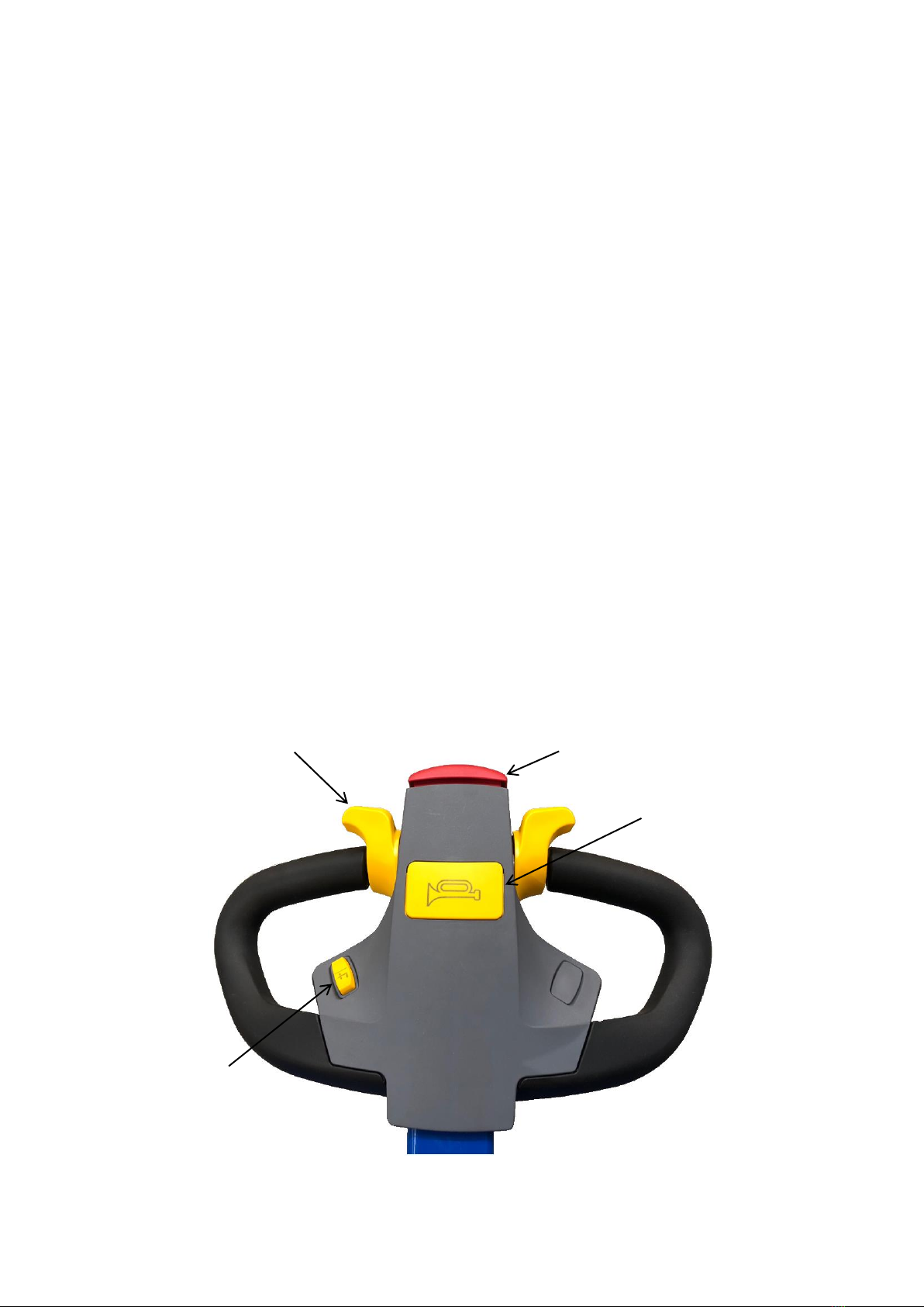
Unit Controls
No.
Function
1
On/Off Isolator Switch
2
Emergency Stop Button
3
Battery Condition Meter
4
Charging Plug
2
3
1
4

11 Operating Instructions: DPC01-R500
NOTE: The battery condition meter only measures voltage in a no-load situation. Under load
the battery condition reading may differ. This means it can only be used as a guide to the
battery status. It is possible that the unit will stop working before the battery condition meter
reads 0%. For this reason, it is a good practice to keep the unit fully charged at all times when
possible. Do not allow the batteries to be left in a discharged state as permanent damage
can be caused to the batteries.
The unit is supplied with the following batteries as standard:
Unit Voltage
Battery Type
Capacity
Weight
24V
12V Yuasa M31-100S Wet Cell Battery
with SMF Lid 330x173x240mm (LxWxH)
100Ah
2 x 23.5kg
When replacing batteries, refer to the guidelines stated under ‘Battery Replacement’. Only
batteries of an equivalent specification and type may be used.
12 Operating Instructions: DPC01-R500
Moving the Unit
Requirements
-If loaded, the load must not exceed the unit’s capacity.
-If loaded, load undamaged.
-Load at correct height for transport (< 500mm).
-Flat and level ground conditions.
-Power key switched to ‘On’.
-Batteries charged.
Procedure
•Pull back on the tiller handle to activate the drive, use the throttle to control forwards
and backwards movement. The further the throttle is rotated, the faster the unit will
go. If the operator releases the throttle the unit will stop. If the tiller is moved into the
vertical or horizontal position the drive is disabled; this is a safety feature.
•The unit can then be manoeuvred to the desired location.
•Travel at a constant speed.
•Adapt your travel speed to the conditions of the route and the load you are
transporting.
•Always transport loads at as low a height as possible to retain the stability of the unit.
THIS UNIT IS DESIGNED FOR USE ON FLAT AND LEVEL FLOOR ONLY
Throttle
Horn
Safety Collision Switch
Lift & Lower Switch

13 Operating Instructions: DPC01-R500
Operating the Lift and Lower Functions
Requirements
-Good ground conditions.
-If loaded, the load must not exceed the unit’s capacity.
-If loaded, load undamaged.
-If loaded, load clamped correctly.
-Batteries charged.
Procedure
•The lift and lower buttons on the unit move the carriage up and down when pressed.
•If the operator releases the lift or lower buttons at any stage, the carriage will stop at
its attained height.
•There is a red emergency stop on the top of the control panel. To stop all powered
movement of the unit, press the button down. To reset the button, lift up.
WARNING –DO NOT LEAVE A RAISED LOAD UNATTENDED
14 Operating Instructions: DPC01-R500
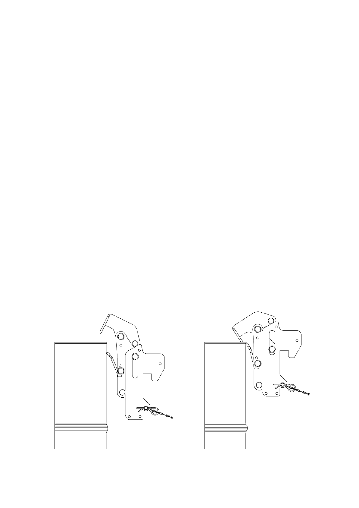
Clamping a Drum
Requirements
-If loaded, the load must not exceed the unit’s capacity.
-If loaded, load undamaged.
Procedure
•Approach the drum so it aligns centrally between the mast uprights of the unit.
•Use the lift/lower functions to position the bottom section of the automatic drum
catch just below the top lip of the drum.
•Drive the unit forward until it contacts with the drum.
•Use the lift function to raise the automatic drum catch; as the catch is lifted it will
securely clamp the top lip of the drum.
•Ensure that the drum is safely secured before transporting to the desired location.
•Always keep the drum as low as practicable during transport to retain the maximum
stability of the unit.
•To unclamp the drum, first lower it to the floor or a supported platform.
•Continue to lower the catch until the top lip of the catch disengages from the drum.
•Reverse the unit away from the drum.
•The drum catch can be moved up or down the rack to suit different sized drums. If
supplied with a pin and R clip, ensure that it is re-inserted before lifting a drum.
Note: Generic unit
shown

15 Operating Instructions: DPC01-R500
Section IV –Unit Maintenance, Troubleshooting and Consumables
Maintenance Checklist
The follow servicing checklist indicates the operations to be performed and the respective
intervals to be observed. Maintenance intervals are defined as:
W = Every 50 service hours, at least weekly
A = Every 1000 service hours, at least annually
● = Standard maintenance interval
During the run-in period –after approx. 100 service hours –the owner must check the wheel
nuts/bolts and re-tighten if necessary.
NOTE: Personal Protective Equipment (PPE) must be worn at all times, see ‘Section I –Correct
Use and Application’ for more information.
NOTE: Maintenance must only be performed by a suitably competent individual as decided
by the company the equipment is intended for use with. All electrical maintenance must only
be performed by qualified personnel.
Manual Braking (if applicable)
W
A
1
Test brakes, adjust bolt if necessary.
●
●
Power Drive Braking (if applicable)
W
A
1
Test automatic brake by accelerating the unit and releasing the throttle/button.
●
●
Hydraulic Operations
W
A
1
Test hydraulic system
●
●
2
Check hydraulic oil and top up, if necessary, to the line or middle of the sight
glass (see ‘Consumables’ for oil type and instructions).
●
●
3
Check that hydraulic ports, hose and pipe lines are secure, check for leaks and
damage.
●
●
4
Check cylinders and piston rods for damage and leaks, make sure they are
secure.
●
5
Test “hydraulic” controls and make sure the labels are present, legible and
complete.
●
6
Replace hydraulic oil (see ‘Consumables’ for oil type and instructions).
●
7
Check hydraulic oil for condensed water, replace if necessary (see
‘Consumables’ for oil type and instructions).
●
Chassis and Superstructure
W
A
1
Check doors and/or covers for damage.
●
●
2
Check labels are legible and complete.
●
●
3
Check guarding for damage and visibility, replace if necessary (see
‘Consumables’ for instructions).
●
●
4
Check chassis and fixing connections for damage.
●
Travel
W
A
1
Check wheels for wear and damage, replace if necessary (see ‘Consumables’
for instructions).
●
●
2
Clean wheels, if required.
●
●

16 Operating Instructions: DPC01-R500
5
Check the load chains tension, adjust chains to the same tension if necessary.
●
6
Check the load chains become slack when fully lowered, adjust if necessary.
●
●
7
Check the load chains for wear and damage, clean if necessary.
●
8
Apply chain lubricant spray, PTFE or food grade chain lubrication spray.
●
9
Visually inspect the mast bearings and check the contact surface wear level,
grease if necessary.
●
10
Check lateral clearance of mast connections and carriage.
●
11
Check carriage and head (load handler) for wear and damage.
●
12
Check channels and bearings for cracks and/or damage.
●
13
If applicable, check clamping pads for wear and/or damage, replace if
necessary (see ‘Consumables’ for instructions).
●
●
14
If applicable, check the blue ratchet strap for wear and/or damage, replace if
necessary (see ‘Consumables’ for instructions).
●
●
Ex Checks (-Ex models only)
W
A
1
Check wheels for dirt and grime, clean if required.
●
●
2
Clean unit, ensure dirt and dust free.
●
●
3
Ensure earthing chains are fitted and in contact with the ground.
●
●
4
Check and clean, if required, the clamping pads on the head of the unit.
●
●
5
Check unit for any damaged painted surfaces, touch up, if necessary, with an
approved touch up paint.
●
●
6
Check, if originally fitted, stainless steel guarding plates are in place and
undamaged.
●
●
7
Ensure earthing strip/strips on the clamping pads contact the load when
clamping. (DRU01-FB and RRH01 units only).
●
●
8
Check continuity between all bare metal (non-powder coated) conductive
parts of the unit, all parts to have a resistance of less than 1 Megaohm to the
earthing chains. (500V +/- 5%) Warning: Only to be checked in a non-ATEX
environment.
●
Pneumatic Operations (if applicable)
W
A
1
Check and replace, if required, pneumatic filter elements.
●
2
Test emergency stop.
●
●
3
If applicable, test the horn.
●
●
4
Disconnect airline to allow air filter regulator to drain.
●
●
Electrical System (if applicable)
W
A
1
Test warning and safety devices in accordance with operating instructions.
●
●
2
Test emergency stop.
●
●
3
If applicable, test the horn.
●
●
4
Check electric wiring for damage (insulation damage, connections). Make sure
wire connections are secure.
●
5
Check contactors and/or relays.
●
6
Ensure that there is no potential difference between the unit chassis and the
battery negative and also between the unit chassis and the charger earth .
●
7
Check battery and battery components for damage. Batteries should be
replaced at maximum of every 3 years.
●
8
Check battery cable connections are secure, grease terminals if necessary.
●
9
Check battery connector for damage, test it and make sure it is secure.
●
10
Charger, check mains connector and mains cable.
●
11
Charger, check the wires and electrical connections are secure and not
damaged.
●
12
Inspect electrical contact to ensure they are clean, tight and free from
corrosion or heats damage from arcing.
●

17 Operating Instructions: DPC01-R500
13
If applicable, check power drive disconnects when charging.
●
14
Ensure battery venting tubes are connected and allow battery gases to exhaust
out of the control box.
●
OPERATORS SHOULD REPORT ANY DEFECTS ON THE UNIT TO THE APPROPRIATE PERSON. IF IN
ANY DOUBT, OR SHOULD REPLACMENT PARTS BE NEEDED, PLEASE CONTACT THE STS TECHNICAL
SUPPORT LINE.
Troubleshooting
When trying to locate a fault, proceed in the order shown in the table.
NOTE: Troubleshooting must only be performed by a suitably competent individual as decided
by the company the equipment is intended for use with.
If, after carrying out the following remedial actions, the unit cannot be restored to operation,
contact the manufacturer’s technical helpline. In order for customer services to react quickly
and specifically to the fault, the following information is essential:
-Unit serial number
-Description of error
-Unit product name
-Current location / Company
Unit does not start (Electrically powered)
Possible Cause
Action
Emergency stop pressed
Reset the emergency stop button
Key switch set to ‘Off’
Set key switch to ‘On’
Battery charge too low
Check battery charge and charge battery
if necessary
Faulty fuse
Check fuses
Load cannot be lifted (Electrically or pneumatically powered)
Possible Cause
Action
The load exceeds the SWL
Reduce mass of load
Load incorrectly secured
See instructions for clamping and lifting
Hydraulic oil level too low
Check hydraulic oil level
Emergency stop engaged
Reset emergency stop button(s)
Air pressure too low, if applicable
Check air supply, if applicable
Air flow too low, if applicable
Check air supply, if applicable
Load cannot be lifted (Manually powered)
Possible Cause
Action
The load exceeds the SWL
Reduce mass of load
Load incorrectly secured
See instructions for clamping and lifting
Hydraulic oil level too low
Check hydraulic oil level
Load cannot be lowered (Electrically or pneumatically powered)
Possible Cause
Action
The load exceeds the SWL
Reduce mass of load
Hydraulic oil level too low
Check hydraulic oil level
Emergency stop engaged
Reset emergency stop button

18 Operating Instructions: DPC01-R500
Load cannot be rotated (Electrically or pneumatically powered)
Possible Cause
Action
The load exceeds the SWL
Reduce mass of load
Off-centre load too high
Reduce off-centre load
Hydraulic oil level too low
Check hydraulic oil level
Emergency stop engaged
Reset emergency stop button
Air pressure too low, if applicable
Check air supply, if applicable
Air flow too low, if applicable
Check air supply, if applicable
Load cannot be rotated (Manually powered)
Possible Cause
Action
The load exceeds the SWL
Reduce mass of load
Off-centre load too high
Reduce off-centre load
Load cannot be clamped (Electrically or pneumatically powered)
Possible Cause
Action
Load outside useable size range
Refer to specification stated in ‘Unit
Description’
Unit cannot be moved (Pedestrian powered)
Possible Cause
Action
Rear parking brakes are engaged
Release the rear parking brakes
Unit cannot be moved (Electrically powered power drive units)
Possible Cause
Action
Emergency stop pressed
Reset the emergency stop button
Key switch set to ‘Off’
Set key switch to ‘On’
Battery charge too low
Check battery charge and charge battery
if necessary
Faulty fuse
Check fuses
Tiller in the vertical or horizontal position
Adjust tiller angle to allow unit movement
Unit cannot be moved (Pneumatically powered power drive units)
Possible Cause
Action
Airline not connected
Reconnect airline
Emergency stop pressed
Reset the emergency stop button
Tiller in the vertical or horizontal position
Adjust tiller angle to allow unit movement

19 Operating Instructions: DPC01-R500
Consumables
All unit consumables are available from STS. The unit must be fitted with original STS
consumables unless otherwise stated. Any deviation from original consumables may result in
injury to personnel or damage to the unit and will invalidate the warranty.
Oil Replacement
STS stackers are factory-equipped with Shell Tellus 32 oil for the hydraulic system. It is
recommended to use as stated or an equivalent when replacing hydraulic oil.
When replacing oil, fill oil to the line or to the middle of the sight glass. Operate all unit
functions to their full extents. Return unit head to its lowest position and recheck the oil level,
top up if required.
Note: Pump and
tank size may vary
Hydraulic oil
filling point
Table of contents
Other STS Lifting System manuals


Popular Lifting System manuals by other brands

Bend-Pak
Bend-Pak HDS-18EA Installation and operation manual

Doosan
Doosan D20S-5 Operation & maintenance manual

HORCHER
HORCHER UNILIFT PRO operating instructions

Garage Smart
Garage Smart MY LIFTER BASIC LIFTER manual

EAE
EAE EE-6604BWF Installation, operation, and parts manual

Efco
Efco SWAPLOADER SL-518 Parts and operation manual

MW TOOLS
MW TOOLS SL300U manual

Ravas
Ravas iForks Service manual

Hailo
Hailo 1-2-3 500 Assembly instructions

Challenger Lifts
Challenger Lifts 40200 Operation installation maintenance manual

HOMECARE PRODUCTS
HOMECARE PRODUCTS EZ-ACCESS TILT Toilet Incline Lift Corded... Installation and user manual

Youngman
Youngman FIT-OUT MASTER user guide


