STS 1656 User manual

1656 Auto-Line Option Owners’ Manual
STS Instruments Page 1 of 32
OWNERS’ MANUAL
1656 Auto-Line Option
STS Instruments
17711 Mitchell North
Irvine, CA 92614
United States of America
Phone Toll Free: 1-800-421-1921 (US and Canada only)
Phone: 1-580-223-4773
Fax: 1-580-226-5757
Email: [email protected]
Web: www.stsinstruments.com

1656 Auto-Line Option Owners’ Manual
STS Instruments Page 2 of 32
1656 Auto-Line Owner’s Manual
P/N 201770-AA
Rev: AB
Date of Publication: May 2016
©2015, All Rights Reserved STS Instruments.
THE INFORMATION CONTAINED IN THIS MANUAL IS PROPRIETARY TO STS INSTRUMENS
AND MAY NOT BE COPIED OR REPRINTED WITHOUT ITS EXPRESSED WRITTEN CONSENT.

1656 Auto-Line Option Owners’ Manual
STS Instruments Page 3 of 32
CERTIFICATION
STS INSRUMENTS CERTIFIES THAT THIS INSTRUMENT WAS THOROUGHLY TESTED AND INSPECTED AND FOUND TO
MEET OR EXCEED ITS PUBLISHED SPECIFICATIONS WHEN IT WAS SHIPPED FROM THE FACTORY.
LIMITED WARRANTY
All products are covered by our standard limited warranty: Your new instrument is warranted to be free
from defects in workmanship and material for a period of (1) year from date of shipment and we will
repair or replace any such product we find to be so defective upon its prepaid return to us. This
warranty is void if the product has been tampered with, or subjected to gross misuse, and is exclusive of
all others, expressed or implied. In case products of other manufacturers are specified as a part of the
above quotation, the warranty of that manufacturer will apply to such items, and our responsibility is
limited to assisting the customer in filing warranty claims with the manufacturer responsible. In the
event that the prepaid return of a system to our Irvine, California plant is impractical and the customer
desires on-site warranty, we expect payment for the actual incurred travel and out-of-factory expense of
our factory representative.
The customer must prepay transportation costs for the return of instrument for warranty service. The
return method will be at the discretion of STS Instruments.
Except as provided herein, STS Instruments makes no warranties to the purchaser of this instrument and
all other warranties, expressed or implied (including, without limitation, merchantability or fitness for a
particular purpose) are hereby excluded, disclaimed and waived.
Any non-authorized modifications, tampering or physical damage will void your warranty. Elimination of
any connections in the earth grounding system or bypassing any safety systems will void this warranty.
This warranty does not cover batteries or accessories not of STS Instruments manufacture. Parts used
must be parts that are recommended by STS Instruments as an acceptable specified part. Use of non-
authorized parts in the repair of this instrument will void the warranty.

1656 Auto-Line Option Owners’ Manual
STS Instruments Page 4 of 32
Contents
1Introduction ..........................................................................................................................................................7
1.1 Manuals ......................................................................................................................................................................... 7
1.2 Background.................................................................................................................................................................... 7
2Technical Specifications ........................................................................................................................................8
2.1 Outputs.......................................................................................................................................................................... 8
2.2 Inputs............................................................................................................................................................................. 8
2.3 AC Input......................................................................................................................................................................... 8
2.3.1 PLC Connector Pins .............................................................................................................................................. 9
2.4 Environmental ............................................................................................................................................................... 9
2.5 Mechanical .................................................................................................................................................................. 10
2.6 Regulatory Compliance................................................................................................................................................ 11
2.7 Included Accessories ................................................................................................................................................... 11
3Installation and Safety ........................................................................................................................................12
3.1 Unpacking and Ship Kit ................................................................................................................................................ 12
3.1 Operator Training ........................................................................................................................................................ 13
3.2 Ergonomics.................................................................................................................................................................. 13
3.3 Important Safety Precautions...................................................................................................................................... 14
3.4 Connecting the Auto-Line unit..................................................................................................................................... 15
3.5 Initial Setup Procedure ................................................................................................................................................ 16
4Theory of Operation ...........................................................................................................................................17
4.1 Auto-Line Multiplexer.................................................................................................................................................. 17
5Operation............................................................................................................................................................18
5.1 Controls, Indicators and Connectors ........................................................................................................................... 18
5.2 Rear Panel Connectors ................................................................................................................................................ 18
5.3 Menu Operation Information ...................................................................................................................................... 19
5.4 Auto-Line Operation Test Setup Menu........................................................................................................................ 19
5.5 Auto-Line Test Result Data Display.............................................................................................................................. 22
5.6 Channel Selection ........................................................................................................................................................ 22
5.7 Utilities Menu – Auto-Line Enable ............................................................................................................................... 23
6Application Notes................................................................................................................................................25
7Maintenance.......................................................................................................................................................26
7.1 Functional Check ......................................................................................................................................................... 26
7.2 Safety Inspection ......................................................................................................................................................... 26
7.3 Annual Maintenance ................................................................................................................................................... 26
7.4 Test Probes.................................................................................................................................................................. 27
7.5 Replacement Parts ...................................................................................................................................................... 27
7.6 Models Part Numbers.................................................................................................................................................. 27
8Service.................................................................................................................................................................28
9CE MARK Declaration of Conformity...................................................................................................................29
Index ............................................................................................................................................................................30

1656 Auto-Line Option Owners’ Manual
STS Instruments Page 5 of 32
Table of Tables
Table 2-1: PLC Connector Pin-out..................................................................................................................................9
Table of Figures
Figure 2-1: 1656 Auto-Line Front Panel – Shown with detachable handles/rack ears................................................10
Figure 2-2: 1656 Auto-Line Rear Panel – Shown without rack ears ............................................................................10
Figure 3-1: Auto-Line Option Connections to STS 1656 Tester ...................................................................................15
Figure 4-1: Auto-Line Option Block Diagram ...............................................................................................................17
Figure 5-1: 1656 Auto-Line Front Panel View ..............................................................................................................18
Figure 5-3: 1656 Auto-Line Rear Panel Connector Locations ......................................................................................18
Figure 5-4: Test Results Screen with Auto-Line enabled .............................................................................................22
Figure 5-5: Test Results Screen with Auto-Line disabled ............................................................................................22
1656 Auto-Line Option Owners’ Manual
STS Instruments Page 6 of 32
CAUTION
READ
Section 3, Installation and Safety
Section 5, Operation
Section 8, Maintenance
of this manual before installing or operating this equipment.
WARNING
IF THIS EQUIPMENT IS NOT INSTALLED AND/OR USED IN A MANNER SPECIFIED
BY THE MANUFACTURER, THE PROTECTION PROVIDED BY THE EQUIPMENT
MAY BE IMPAIRED

1656 Auto-Line Option Owners’ Manual
STS Instruments Page 7 of 32
1Introduction
1.1 Manuals
This manual covers all aspects of the STS Instruments’ model 1656 Auto-Line Option Battery
Element Tester. This includes setup, programming, use, specifications, and principle of
operation, maintenance and calibration. The Auto-Line option can only be used in combination
with the 1656 Battery Element tester.
1.2 Background
For over 30 years, the STS Instruments Battery Element Testers have been the de-facto
benchmark for Battery Cell quality testing. The new 1656 model builds on this legacy of reliable,
high volume testing using a state-of-the-art digital design made possible by advanced
microcontrollers (MCUs) and high resolution, fast Analog to Digital conversion (ADC) of voltage
and current test signals. This advanced and modern digital design is complemented by a
convenient operator interface using a large LED backlight, color graphic LCD screen that displays
settings that results in large, easy to read operator information.
The Model 1656 Auto-Line option is designed to support automated production line testing of
lead-acid battery using an automated test fixture to test up to six cells in a single operation. To
this end, the Auto-Line option generates six multiplexed high voltage surge test channels from a
single 1656 Battery Element tester unit. All testing and channel switching functions are
controlled by the 1656 tester using its PLC I/O connection to the Auto-Line option unit.
The Auto-Line chassis dimensions match those of the 1656 Battery Element tester so both can
be stacked on top of each other or rack mounted. The use of the rear panel HV connection
option (option –RPC) on the 1656 Battery Element Tester is recommended.
Note: The Auto-Line is electrically and functionally compatible with the 1656-Bench version of
the 1656 as well but differs from this unit in size.
The Model 1656 Auto-Line option is equipped with a Modular Line Cord Assembly and a
universal AC input supply that allows the tester to operate on a nominal 90Vac through 264Vac
input at 50 or 60 Hz.

1656 Auto-Line Option Owners’ Manual
STS Instruments Page 8 of 32
2Technical Specifications
This section includes performance specifications for the 1656 Battery Element Tester. All
specifications are valid over the stated temperature. Calibration is performed at 23°C ± 5°.
2.1 Outputs
Parameter Specification Notes
High Voltage Channels
6
Test Voltage
Range
300 – 3000 V peak
Resolution
10 V
Accuracy
±2.0% F.S.
Shape
Pulse
Duration
120 μsec (typical)
Test Interval
Programmable from 200 to 5000 msec
High Voltage Connections
Rear Panel Sockets
Six Pairs Amphenol / Alden Red/Black
2.2 Inputs
Parameter Specification Notes
High Voltage Channels
1
Connects to 1656-RPC BET HV Output
High Voltage Connections
Rear Panel Sockets
One Input Pair Amphenol / Alden Red/Black
Control Connectors 1x 1656 PLC, HD DB15 Female
1 x PCL Pass Through, HD DB15 Female
2.3 AC Input
Parameter Specification Notes
AC Input Voltage
Type
Universal Input
Range
100Vac – 240Vac ±10%
RMS
Frequency
47 – 63 Hz
AC Input Current
Max.
500 mA
Input Power Factor
Typical
0.98
Input Fuse
Type
250V, 0.5A, Slow Blow
Dimension
5 x 20 mm / 0.20” x 0.80”

1656 Auto-Line Option Owners’ Manual
STS Instruments Page 9 of 32
Parameter Specification Notes
On/Off Switch
Type
Rocker Type, Front Panel. Press O to turn Off
Line Cord
Type
IEC 60329, C13, Detachable
AC Input Connector
Type IEC 60320, C14
2.3.1 PLC Connector Pins
Pin
Direction Signal Description
1~3
n/c
4
Digital Output
Reserved for Auto-line Option
Do not connect
5
Ground
Analog/Digital Signal Ground
Signal Ground for non-Relay Outputs
6~8
n/c
9
Digital Output
Reserved for Auto-line Option
Do not connect
10~14
n/c
15
Digital Output
Reserved for Auto-line Option
Do not connect
Table 2-1: PLC Connector Pin-out
Note: Do NOT use VGA monitor cables to connect to the PLC interface as one or
more pins on these cables are shorted to ground. Instead, use the provided
black HD15 to HD15 cable (P/N 201753AA-001) or a straight-through HD
DE15 to HD DE15 cable. Example L-Com model CHD15MF-5 male/female
cable equivalent.
2.4 Environmental
Parameter Specification Notes
Temperature
Operating
32 to 104° F/ 0 to 40°C
Storage
-2 to 158° F / -20 to 70° C
Cooling
Convection
Humidity
Operating
5% to 95% non-condensing
Altitude
Operating
6000 ft. / 2000 meters

1656 Auto-Line Option Owners’ Manual
STS Instruments Page 10 of 32
2.5 Mechanical
Figure 2-1: 1656 Auto-Line Front Panel – Shown with detachable handles/rack ears
Figure 2-2: 1656 Auto-Line Rear Panel – Shown without rack ears
Parameter Specification Notes
Dimensions
Width
19” / 483 mm
16.7” / 425 mm
Incl. rack ears
No rack ears.
Height
3.5” / 89 mm (2U)
Excluding rubber feet.
Depth
8.5” / 216 mm
Excluding terminals
Shipping
Width
21.7” / 550 mm
Height
8.8” / 224 mm
Depth
16.3” / 415 mm
Rack Mount
Method
Removable Handles with Rack Ears
Weight
Net
15.4 lbs. / 7 Kg
TBD
Shipping
20 lbs. / 9 Kg

1656 Auto-Line Option Owners’ Manual
STS Instruments Page 11 of 32
2.6 Regulatory Compliance
Parameter Specification Notes
CE Mark
EMC
IEC61326-1:2013
Safety
IEC61010-1:2010
2.7 Included Accessories
Accessories listed are included with each 1656 Auto-Line unit as part of the ship-kit. Additional
quantities may be purchases separately through customer service.
Part Number Description Qty. Length
201746-AA
HV Cabling from 1656 RPC to Auto-line chassis – Red
1
1 m
201747-AA
HV Cabling from 1656 RPC to Auto-line chassis – Black
1
1 m
201748-AA
HV Wire, terminated one end only – White
12
1 m
201753-AA-001
HD-DB15 M/M Control Cable - black
1
1 m
1656 Auto-Line Option Owners’ Manual
STS Instruments Page 12 of 32
3Installation and Safety
This chapter describes required installation provisions and precautions necessary to deploy this
equipment effectively and above all safely. Please ensure anyone that will be assigned to
operate this equipment is fully qualified and trained to operate this equipment in a safe manner.
3.1 Unpacking and Ship Kit
Before removing the 1656 Auto-Line from its container, carefully inspect the shipping carton for
any signs of damage or signs of dropping during transit. If no damage is evident, carefully
remove the 1656, documentation and accessories from the shipping carton. Check the 1656
Auto-Line main unit for any visible sign of damage before proceeding with any installation.
If damage is evident, keep the original carton and file an insurance claim with the carrier.
Check all content of the 1656 Auto-Line shipping carton to make sure you have received all
items that make up the product. The table below lists the included items.
Part Number Description Notes /Quantity
Unit
1656 Auto-Line Battery Element Tester, Main Unit. STS P/N 201903
AC Line Cord
AC Line Cord, IEC60320, Type C13
Cables
201758
Chassis Ground Cable, 1m/3.3’ – Green/Yellow
1
201746-AA
HV Cabling from 1656 RPC to Auto-line chassis, 1m/3.3’ –
Red
1
201747-AA
HV Cabling from 1656 RPC to Auto-line chassis, 1m/3.3’ –
Black
1
201901
HV Wire Kit, terminated one end only, 3m/9.8’ – White
[Note: Individual cables are P/N 201902]
12
201753-AA-001
HD-DB15 M/M Control Cable - black
1
Documentation
WARNING
IF THIS EQUIPMENT IS NOT INSTALLED AND/OR USED IN A MANNER
SPECIFIED BY THE MANUFACTURER, THE PROTECTION PROVIDED BY THE
EQUIPMENT MAY BE IMPAIRED

1656 Auto-Line Option Owners’ Manual
STS Instruments Page 13 of 32
Part Number Description Notes /Quantity
201770-AB 1656 Owners’ Manual, PDF format Available on line
Certificate of Conformance
1
Calibration Certificate
1
3.1 Operator Training
One of the more important ways to promote safety is through operator training. Benefits of
training are twofold. First, thorough training promotes safety, which may significantly reduce
injuries on the job. Second, it ensures adequate testing of the product which helps increase
product reliability.
Generally, commercial high voltage test equipment in itself is not hazardous. The hazards come
about when the equipment is improperly used. These testers, when used properly and in a safe
manner, can greatly contribute to the quality and reliability of your product. If used incorrectly
and without proper consideration for safety, they represent a hazard for both operating
personnel and casual bystanders. We strongly recommend proper training for all personnel
involved in testing.
3.2 Ergonomics
An additional consideration in any test station is operator comfort. This is affected by the
operator’s position, which includes the chair, table, test equipment, the object under test and
the test procedure itself. The chair and work bench or table should be non-conductive and the
table or work surface as large as possible to allow sufficient room for the test equipment and
the object under test. Studies should be made of the test requirements and work habits and
steps taken to ensure that any unusual or unnatural motion is not required and to eliminate any
repetitive motions that may produce injuries over time such as carpel tunnel syndrome.
1656 Auto-Line Option Owners’ Manual
STS Instruments Page 14 of 32
3.3 Important Safety Precautions
CAUTION
ALWAYS FOLLOW RECOMMENDED SAFETY PRACTIVES WHEN OPERATING
THIS EQUIPMENT
After the equipment has been installed, a careful study should be made of the test station to
determine what, if any, safeguards are needed. It is suggested that any electrical test station
involving voltages in excess of 42.4 volts peak (approximately 30 volts RMS) should be equipped
with safeguards. These should operate both for the protection of the operating personnel and
for the protection of casual bystanders. At the minimum, safeguards should prevent the
operating personnel or casual bystanders from coming into contact with the test circuit. In the
event electrical interlocks of any sort are required, either to insure that guards are in place, or to
insure that the operator’s hands are in a safe location, we will be happy to provide suggestions
and schematics for safety interlocking our test equipment.
The test procedure should be well thought out to ensure that it adequately tests the product to
the desired criteria but that the procedure does not require the operator to perform tasks that
are unsafe. The product should never be touched during a test.
Good safety practice dictates labeling of hazards properly. Since high voltage testing can be
hazardous, the work station should be labeled. Naturally, the location of the label should be
carefully selected so that it can be placed in a location that will do the most good.
In some cases, this may be on the test instrument itself, and in others, it may be in a location
directly in front of the operator, somewhat removed from the instrument.
1656 Auto-Line Option Owners’ Manual
STS Instruments Page 15 of 32
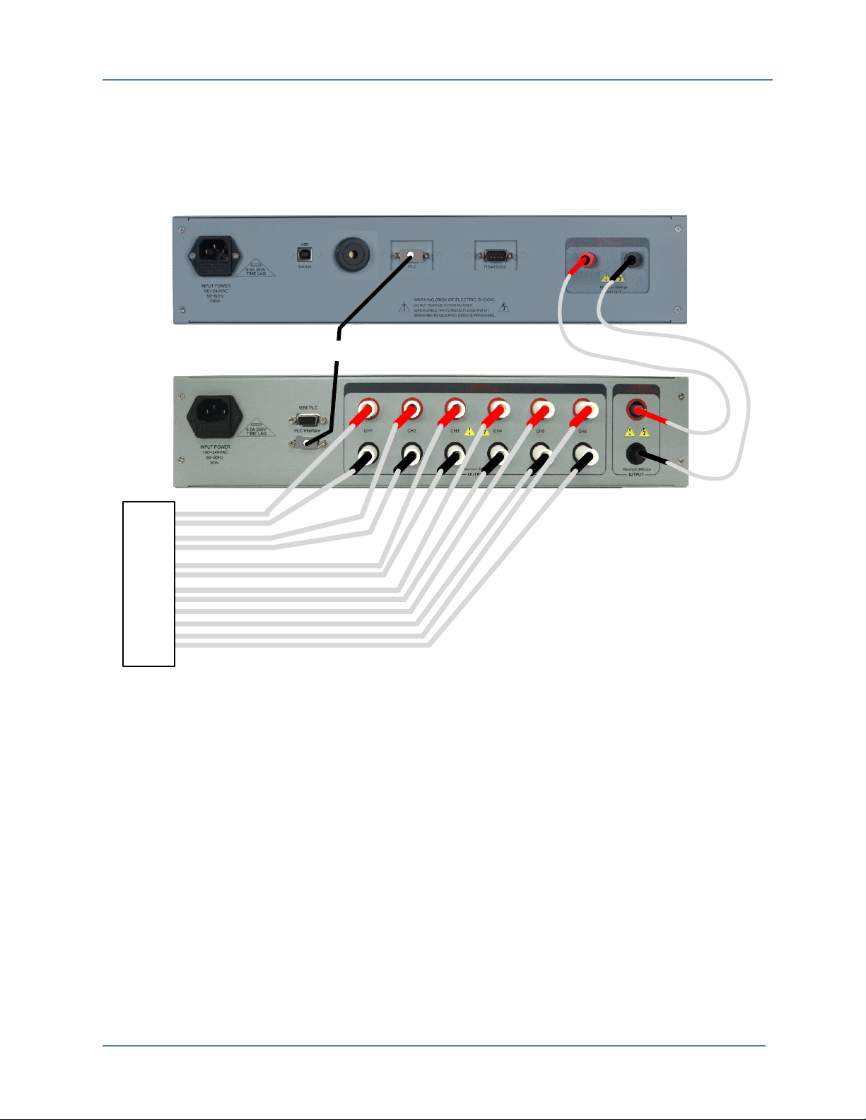
3.4 Connecting the Auto-Line unit
The Auto-Line needs to be connected to a STS1656 unit to operate. The required connection
diagram is shown below.
201753-AA-001
PLC CABLE
201746-AA
201747-AA
201748-AA
TEST
FIXTURE CH1
CH2
CH3
CH4
CH5
CH6
Figure 3-1: Auto-Line Option Connections to STS 1656 Tester
Required cabling is provided in the Auto-Line ship kit. If the distance between the Auto-Line
chassis and the text fixture exceeds the length of the fixture wires provided with the Auto-Line
unit, contact STS Instruments customer service to purchase longer wires. In general however,
the distances between the Auto-Line test unit and the test fixture should be kept as short as
possible.

1656 Auto-Line Option Owners’ Manual
STS Instruments Page 16 of 32
3.5 Initial Setup Procedure
Proceed as follows:
1. Insert the AC line cord into a suitable AC outlet. The 1656 Auto-Line has a universal input
and will operate from any voltage between 100Vac RMS L-N and 240Vac RMS L-N.
2. The included ground wire (Green/Yellow color) may be used to ground the Auto-Line chassis
to a cabinet or other instrument if needed. Grounding is also provided by the modular line
cord as long a suitable three prong grounded outlet is used to power the unit.
3. Connect the PLC control cable between the main 1656 unit’s rear panel PLC connector and
the 1656 Auto-Line rear panel 1656-PLC connector. (Note: the two PLC connectors on the
Auto-Line option are wired in parallel so either one may be used. This allows other signals
available on the PLC interface to be used as well.)
4. Connect the two supplied high voltage wires from the 1656 main unit rear panel female
output sockets and the 1656 Auto-Line rear panel male input sockets. Red connector to Red
socket and Black connector to Black socket. Refer to Figure 3-1.
5. Connect the six high voltage output channels to the battery probe test fixture. (Not supplied
with the unit. Contact manufacturer for test fixture services. Refer to Figure 3-1.
6. Turn the main 1656 tester unit ON using its front panel toggle switch.
7. Turn on the 1656 Auto-Line unit using its front panel toggle switch. (Actual order of turning
both units on is not important).
8. Auto-Line option is now ready for use. Consult section 5, “Operation”, for programming
information.
1656 Auto-Line Option Owners’ Manual
STS Instruments Page 17 of 32
4Theory of Operation
This section provides background information on the test methodology used by the 1656 Auto-
Line option.
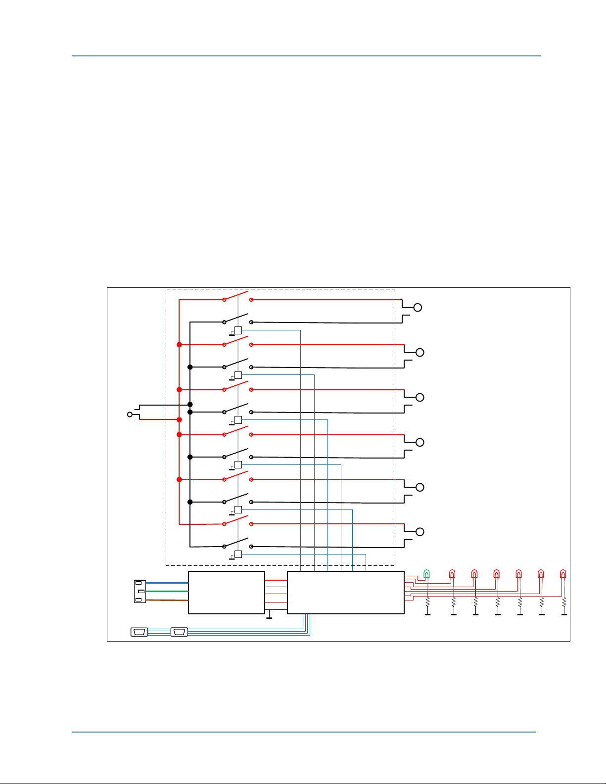
4.1 Auto-Line Multiplexer
The Auto-Line unit acts as a six channel high voltage path multiplexer controller by the main
1656 tester through the PLC interface. The Auto-Line option allows the test voltage to be
applied to up to six separate channels (CH1 through CH6). Each channel is fully isolated from all
other channels.
A logic relay controller controls the timing of relay open/close and ensure relay settling times
are not violated. There is an indicator for power on and one for each active channel. (lit when
channel is selected).
The functional block diagram illustrates the operation of the Auto-Line option.
RLY
RLY
RLY
RLY
RLY
RLY
HV INPUT
SOCKET
CHANNEL 1
CHANNEL 2
CHANNEL 3
CHANNEL 4
CHANNEL 5
CHANNEL 6
DC BIAS SUPPLY
+12V
-12V
COM
+5V
COM
CH1 CH2 CH3 CH4 CH5 CH6
AC LINE INPUT
PLC
POWER ON CH1 CH2 CH3 CH4 CH5 CH6
RRRRRRR
+5V
CH1
CH2
CH3
CH4
CH5
CH6
RELAY CONTROLLER
PLC
HIGH VOLTAGE PATH
Figure 4-1: Auto-Line Option Block Diagram

1656 Auto-Line Option Owners’ Manual
STS Instruments Page 18 of 32
5Operation
This chapter describes the various front panel controls, menu’s, settings and readouts on both
the main 1656 main tester and the Auto-Line chassis that are used to interface with the
operator. It is strongly recommended that the user familiarizes him / her with the contents of
this chapter before attempting to operate this equipment.
5.1 Controls, Indicators and Connectors
Figure 5-1: 1656 Auto-Line Front Panel View
Controls on the 1656 Auto-Line are limited to the power On/Off switch which also doubles as a
power on indicator.
There are six LED indicators on the 1656 Auto-Line units’ front panel. These indicators show
which channel is selected, if any. Only one channel can be selected at any one time.
Functions of the various controls and indicators found on the front panel of the 1656 Battery
Element Tester are covered by the STS 1656 Owner’s Manual, P/N 201353. This manual is
supplied with the main STS 1656 battery element tester unit.
5.2 Rear Panel Connectors
The available connectors located on the rear panel of the 1656 Auto-Line chassis are shown in
the Figure below.
Figure 5-2: 1656 Auto-Line Rear Panel Connector Locations

1656 Auto-Line Option Owners’ Manual
STS Instruments Page 19 of 32
5.3 Menu Operation Information
This section only covers use of the 1656 Auto-Line option from the 1656 tester’s front panel. It is
assumed that the user is familiar with the 1656 Operator Manual and/or 1656 Owner’s Manual
which are both supplied with the 1656 Battery Element Tester.
5.4 Auto-Line Operation Test Setup Menu
The Auto-Line can be operated from the 1656 tester once it has been selected in the Test Setup
screen.
The Test Setup menu is used to program the 9 pre-stored test level and trip level settings for the
tester. This allows up to nine battery types or models to be preprogrammed for immediate
recall.
The screen shown above displays settings for setup number 1. To select a different setup
number, press the key to return to the Test Result screen and change the active test
setup selection to the desired number.
ESC

1656 Auto-Line Option Owners’ Manual
STS Instruments Page 20 of 32
TEST SETUP <n> MENU
Entry Type Description
TEST VOLTAGE Parameter
Sets the test voltage level for the selected test setup. For
most battery types, a test voltage between 1500 V and
2000 V should be sufficient. Setting the test voltage too
low may not allow possible defects to be found. Setting
it too high could result in damage to the unit under test.
To change the voltage level, mode the selector bar to
the Voltage field and press the Shuttle to enter the EDIT
mode. The Edit mode is indicated by a flashing cursor in
the selected parameter box. Once in edit mode, turn the
shuttle left or right to decrement or increment the test
level. Once the desired level is displayed, press the
Shuttle again (ENTER) to accept the new value. This
accepts the new value and exits out of the EDIT mode.
The selector bar can now be move to the next
parameter field or menu entry using the Shuttle.
TEST TRIP LEVEL UPPER
LOWER
Sets the pass/fail upper and lower trip levels. The
appropriate trip level varies by battery separator type
and construction. It may require testing on several
batteries to come up with suitable upper and lower trip
levels. This process of empirically establishing the trip
level for a specific make/model battery can be
accomplished using the LEARN MODE. (See next)
Note that the TRIP1, TRIP2 and TRIP3 buttons can be
used to quickly set both levels at once. They can then be
adjusted up or down using the shuttle.
Q SENSITIVITY The Q sensitivity setting combines up to five Q readings
and compares them against the same multiple of the
pass/fail limit values. Changes the Q sensitivity value
automatically adjust the trip level settings.
Other manuals for 1656
2
Table of contents
Other STS Test Equipment manuals


