RJG Sensor PreCheck User manual

USER GUIDE
Testing and diagnostics.
Error Reporting.
Sensor Validation.
Training and Technology for Injection Molders

PRINT DATE 01.19.2021
REVISION NO. 2.4.2

USER GUIDE | RJG, INC. SENSOR PRECHECK i
USER GUIDE
USER GUIDE INTRODUCTION III
DISCLAIMER III
COMPLIANCE III
EN61326‑1:2013 III
IEC61010‑1:2010 III
PRIVACY III
ALERTS III
PRODUCT OVERVIEW IV
QUICK START GUIDE 1
START EQUIPMENT AND APPLICATION 2
RUN AN AUTOMATED SENSOR TEST 3
RUN A MANUAL SENSOR FORCE TEST 4
STRAIN GAGE SENSORS 4
PIEZOELECTRIC SENSORS 5
GENERATE AND DISTRIBUTE REPORTS 6
OVERVIEW 7
SENSOR PRECHECK HARDWARE 8
AP32C 8
LYNX SENSOR CABLE 9
TABLET 9
SENSOR PRECHECK APPLICATION 10
AUTOMATED SENSOR TEST 11
MANUAL STRAIN GAGE SENSOR FORCE TEST 12
MANUAL PIEZOELECTRIC SENSOR FORCE TEST 13
SENSOR TEST RESULTS 14
SENSOR TEST REPORTS 15
SENSOR TEST SPECIFICATIONS 16

RJG, INC. SENSOR PRECHECK | USER GUIDE
ii
USER TOOLS 17
AUTOMATED SENSOR TESTS 18
MULTIPLE SENSORS 18
MANUAL SENSOR FORCE TESTS 19
STRAIN GAGE SENSORS 19
PIEZOELECTRIC SENSORS 20
SENSOR TEST REPORTS 21
SETTINGS 23
INSTALLATION AND SETUP 24
APPLICATION DOWNLOAD AND INSTALL FROM TABLET 24
REFRESH APPLICATION 24
REFRESH SENSOR PRECHECK LIST 25
REFRESH SENSOR LIST 26
UPDATES 27
APPLICATION 27
FIRMWARE 27
TROUBLESHOOTING 29
STRAIN GAGE SENSORS 30
COMMUNICATION FAILURE 30
GAGE/WIRE TEST FAILURE 30
ZERO SHIFT FAILURE 30
FORCE TEST FAILURE 30
PIEZOELECTRIC SENSORS 31
COMMUNICATION FAILURE 31
FORCE TEST FAILURE 31
FORCE TEST PASS WITHOUT APPLICATION OF FORCE 31
DRIFT FAILURE 32
KNOWLEDGE BASE 33
CUSTOMER SUPPORT 34
USER GUIDE | RJG, INC. SENSOR PRECHECK iii
USER GUIDE INTRODUCTION
Read, understand, and comply with all following instructions. These instructions must be kept available for reference at
all times.
PRIVACY
Designed and developed by RJG, Inc. Manual design,
format and structure copyright 2020 RJG, Inc. content
documentation copyright 2020 RJG, Inc. All rights
reserved. Material contained herein may not be copied
by hand, mechanical, or electronic means, either whole
or in part, without the express written consent of RJG,
Inc. Permission will normally be granted for use in
conjunction with inter‑company use not in conflict with
RJG’s best interests.
ALERTS
The following three alert types are used as needed to
further clarify or highlight information presented in the
manual:
Term
A definition of a term or terms used in the text.
NOTE A note provides additional information about a
discussion topic.
CAUTION A caution is used to make the operator aware
of conditions that can cause damage to equipment and/or
injury to personnel.
DISCLAIMER
Inasmuch as RJG, Inc. has no control over the use to
which others may put this material, it does not guarantee
that the same results as those described herein will be
obtained. Nor does RJG, Inc. guarantee the effectiveness
or safety of any possible or suggested design for
articles of manufacture as illustrated herein by any
photographs, technical drawings, and the like. Each user
of the material or design or both should make his own
tests to determine the suitability of the material or any
material for the design as well as the suitability of the
material, process, and/or design for his own particular
use. Statements concerning possible or suggested uses
of the material or designs described herein are not to be
construed as constituting a license under any RJG, Inc.
patent covering such use or as recommendations for use
of such material or designs in the infringement of any
patent.
COMPLIANCE
The CoPilot™ System (including Sensor PreCheck Version
2.0)” has been designed and tested in accordance with
the following standards:
EN61326‑1:2013
EMC Requirements for electrical equipment for
measurement, control, and laboratory use. Intended for
use in industrial locations.
IEC61010‑1:2010
Safety requirements for electrical equipment for
measurement, control, and laboratory use.
The Sensor PreCheck system conforms to
European Conformity (CE) requirements and is
eligible for sale in the European Union(EU).

RJG, INC. SENSOR PRECHECK | USER GUIDE
iv
PRODUCT OVERVIEW
The Sensor PreCheck provides testing of up to 30 Lynx
cavity pressure sensors simultaneously, including the
following:
Automatic Testing
• Strain Gage
Sensors
Lynx Communication, Zero Offset, and Broken Wire/
Failed Gage Tests
• Piezoelectric
Sensors
Lynx Communication and Drift Tests
Manual Testing
• Strain Gage Sensors Basic Force Test
• Piezoelectric Sensors Basic Force Test
Specifications
Compatible Sensor Models
• Strain Gage
LS‑B‑127‑50/125/500/2000, LS‑B‑159‑4000,
LES‑B‑127‑50/125/500/2000, LES‑B‑159‑4000,
MCSG‑B‑60‑50/250, MCSG‑B‑127‑125/500/2000, &
MCSG‑B‑159‑4000
• Piezoelectric
6157, 6159, 9204, 9210, & 9211
Hardware
• Power Requirements 12 V DC
• Max Lynx Sensors 30
Application
• Tablet Samsung Galaxy Tab 4
• OS Requirements Android 4.4 KitKat or Later
• Memory Required 10 MB
This Product Includes:
• 1RJG, Inc. AP 32C with USB WiFi Adapter (TP Link
TL‑WN7225N v3.8)
• 18" Samsung Tablet with USB cable
• 1OtterBox Tablet Case
• 112 V DC Power Supply Cable
• 1Lynx Cable


QUICK START GUIDE | RJG, INC. SENSOR PRECHECK
2
START EQUIPMENT AND APPLICATION
Connect the power supply cable to the AP32C 1power
port and a power source. The green 2power indication
light will indicate that the AP32C is on; if no green light
is visible the AP32C is off.
Connect the Lynx cable to the AP32C 3Lynx input, and
the sensor(s) to be tested; ensure the provided USB WiFi
adapter is inserted in the AP32C USB port.
Select the RJG Sensor PreCheck 4application icon
on the tablet home page to start the application.
NOTE WiFi must be enabled on the tablet to connect to
the Sensor PreCheck.
NOTE For optimal performance the tablet should be
physically near the Sensor PreCheck and the sensors
being tested.
2
1
3
4
RJG, INC. SENSOR PRECHECK | QUICK START GUIDE 3
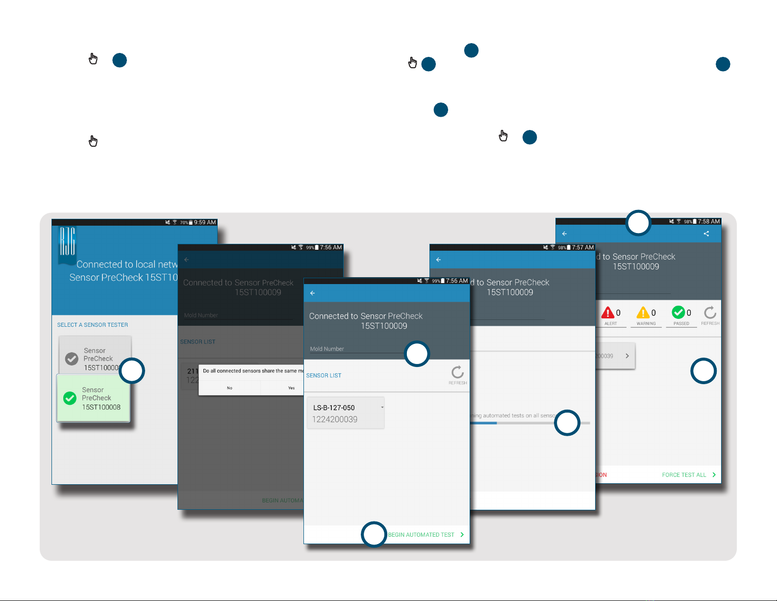
RUN AN AUTOMATED SENSOR TEST
Select a 1Sensor PreCheck icon from the application
home page with which to connect. The Sensor PreCheck
icon will be grey until selected, and will turn green after
selection. If multiple sensors are attached for testing,
a pop‑up window will appear to determine if each
connected sensor is the same or different model(s).
Select the appropriate response for the connected
sensor(s) to continue.
Enter the 2Mold Number in the provided field. Select
3Begin Automated Test to test the sensor(s). The 4
Progress Bar will indicate the test progress. Wait for the
test to complete.
The 5automated test complete page will indicate any
alerts, warnings, and the number of sensors that passed
the test. Select a 6sensor to enter the sensor
information, including Location, Cavity Name, Pin Size,
Sensitivity, Sensor Model, and Sensor Serial Number.
Complete the testing by running a force test (page
4).
1
5
6
4
3
2
QUICK START GUIDE | RJG, INC. SENSOR PRECHECK
4
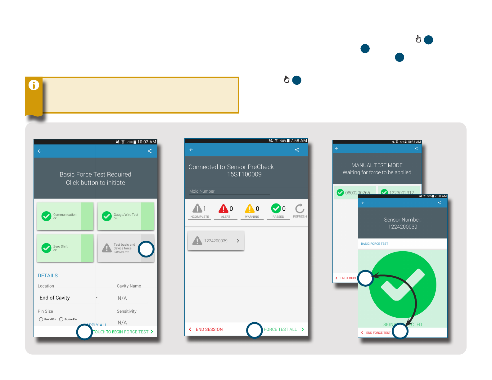
RUN A MANUAL SENSOR FORCE TEST
Sensor force tests require the operator to physically
press on the sensor(s) being tested in order for the
Sensor PreCheck to evaluate if the sensor is detecting
force.
NOTE The application will time out if no signal is
received from the sensor in a specified length of time; be
ready to apply force to the sensor(s).
STRAIN GAGE SENSORS
After completing an automated test, select 1Test
Basic and Device Force OR 2Touch to Begin Force
Test to force test a single sensor, OR 3Force Test All to
force test all sensors.
Select 4End Force Test to return to the test results
screen when the force test is complete.
3
2
1
4
4
Table of contents
Other RJG Test Equipment manuals


