STS 1660 User manual

Page 1
OPERATOR’S MANUAL
MODEL 1660
INTRODUCTION
The Series 1660 designates a family of high voltage surge testers that are intended for the testing
of coils and windings of all types for defects and weaknesses within the winding. These include
such obvious defects as turn-to-turn shorts and layer insulation failures and weaknesses.
Specifications
Input Requirements
110 Volts +/
-
15%, 50/60 Hz,
1
.
5
/
1
A
Output Voltage
400
–
5000 Volts Peak
Pulse Energy
Variable to 0.25 Watt
-
Seconds
Maximum Operatin
g Range
Temperature: 0
–
40 deg. C
Relative Humidity: 5 – 85 % Non-Condensing
Altitude: 0 – 3000 m
Vibration: 0 – 2 g
Dimensions (WxHxD)
48.26 cm x 13.34 cm x 44.45 cm
Weight
20 kg
The measurement terminals on the Model 1660 Surge Tester are rated for
measurement category I as defined in IEC International Standard EN 61010-
1. Measurement category I is for measurements performed on circuits not
directly connected to mains. Do not use this equipment for measurements in
measurement categories II, III, or IV. Do not use this equipment for any
purpose other than as described in this manual.

Page 2
PRINCIPLE OF OPERATION
While the surge tester is essentially a dielectric tester, unlike the typical Hipot tester, it is used to
test for internal weaknesses and faults rather than for weaknesses and faults between electrically
isolated elements such as wiring to frame or winding to winding.
Insure the unit is operated within the following environmental specifications:
Temperature: 0 – 40 Degrees C.
Relative Humidity: 0 – 85%, Non-condensing
Vibration: 2 g. maximum
Ventilation: No special requirements
Of prime consideration and importance in the layout and installation of a test station is to
insure the safety both of the operator and any visitors or casual bystanders, invited or
otherwise. As a general rule it is suggested that each test area be in a location with
minimum distractions.
As shipped from the factory, the Model 1660 Surge Tester is configured as a bench top
unit. If desired, the unit may be rack mounted with user supplied slides.
One of the more important ways to promote safety is through operator training. Benefits
of training are twofold. First, thorough training promotes safety, which may significantly
reduce injuries on the job. Second, it ensures adequate testing of the product which helps
increase product reliability.
An additional consideration in any test station is operator comfort. This is affected by the
operator’s position, which includes the chair, table, test equipment, the object under test
and the test procedure itself. Locate the unit so that the operator has easy access to all
controls and connectors. The chair and work bench or table should be nonconductive and
the table as large as possible to allow sufficient room for the test equipment and the
object under test. Studies should be made of the test requirements and work habits and
steps taken to ensure that any unusual or unnatural motion is not required and to
eliminate any repetitive motions that may produce injuries such as carpel tunnel
syndrome.
CAUTION: The use of high voltage test equipment can be hazardous
to personnel. It is advised that all involved in the use of this equipment
be made aware of this fact, and that a thorough study be made of any
hazards involved in the contemplated usage of the equipment.
Reference should be made to safety material furnished with the unit
and to the Basic Facts booklet accompanying this manual, which
includes additional material on safety considerations.
•This unit is equipped with a three-prong grounding type line
plug. It is essential that it be utilized only with a mating three-
terminal receptacle, properly grounded in accordance with
electrical codes.
•This unit is designed for indoor use.

Page 3
After the equipment has been installed, a careful study should be made of the test station
to determine what, if any, safeguards are needed. It is suggested that any electrical test
station involving voltages in excess of 42.4 volts peak (approximately 30 volts RMS)
should be equipped with safeguards. These should operate both for the protection of the
operating personnel and for the protection of casual bystanders. At the minimum,
safeguards should prevent the operating personnel or casual bystanders from coming into
contact with the test circuit. In the event electrical interlocks of any sort are required,
either to insure that guards are in place, or to insure that the operator’s hands are in a safe
location, we will be happy to provide suggestions and schematics for safety interlocking
our test equipment.
The test procedure should be well thought out to ensure that it adequately tests the
product to the desired criteria but that the procedure does not require the operator to
perform tasks that are unsafe. The product should never be touched during a test.
Good safety practice dictates labeling of hazards properly. Since high voltage testing can
be hazardous, the work station should be labeled. Naturally, the location of the label
should be carefully selected so that it can be placed in a location that will do the most
good. In some cases, this may be on the test instrument itself, and in others, it may be in
a location directly in front of the operator, somewhat removed from the instrument.
A final word about high voltage testers. Generally, commercial high voltage test
equipment is not in itself hazardous. The hazards come about when the equipment is
improperly used. These testers, when used properly and in a safe manner, can be a check
on the quality and reliability of your product. If used incorrectly and without proper
consideration for safety, they represent a hazard for both operating personnel and casual
bystanders. We strongly recommend proper training for all personnel involved in testing.
Page 4
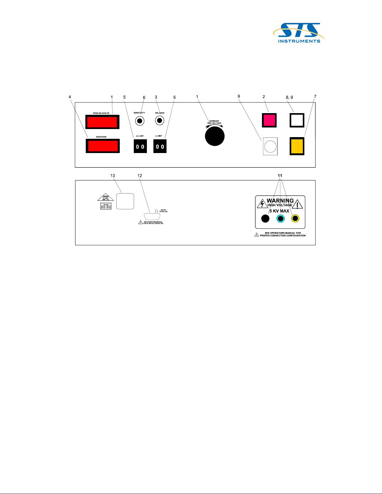
CONTROLS AND INDICATORS
In using this equipment, it must be kept in mind that maladjustment of the controls can
completely smother the indications. This can be avoided by fully understanding the various
adjustments and by following the suggested procedures. We will first review the important
adjustments and then outline procedures.
1. VOLTAGE CONTROL – This knob adjusts the actual voltage applied during test.
Since some regulation exists in the power supply, the voltage control should be
adjusted under actual test conditions. The voltmeter reads actual peak test voltage at
the output terminals.
2. RESET SWITCH – The Reset Switch is depressed to stop a test cycle before
completion or clear reject signals.
3. BALANCE CONTROL – This control is used to adjust the reference voltage to
establish a zero reading with a known good part. A Balance reading of 10 (full CW)
indicates minimum volts or very low Return Signal for part under test.
4. DEVIATION METER – This meter indicates the difference between back EMF and
the reference voltage. Deviation meters will normally read zero with a good part and
up or down scale for defective or wrong parts.
5. LIMIT SWITCH – These thumbwheel controls to set the accept/reject limits.
6. SENSITIVITY CONTROL – This control adjusts meter sensitivity and is normally
set as necessary to keep meter readings nominal with the normal variation of parts
and at the same time, provide adequate sensitivity to pick out defective parts. A
Sensitivity Dial reading of 10 (full CW) produces minimum sensitivity and a lower
Return Signal from part under test to the metering circuits.
Page 5
7. POWER SWITCH - Mounted in the lower right corner of the panel, this switch is
used to control input power. Normal position of this switch is top edge depressed.
8. TEST SWITCH – Mounted above Power Switch. The Test Switch is used to initiate
the automatic time cycle. When the preset time cycle is completed, the test voltage
will be turned OFF. However, if the switch is held in the TEST position, this will
override the timer and the unit will remain ON until the switch is released.
9. PILOT LAMP – This lamp mounted in the power switch indicates that the AC power
is ON.
10. DWELL TIMER – Located below the Reset Switch is the adjustment for Dwell
Time. Adjust to times required between .1 & 5 seconds.
11. TERMINALS – (back panel ) Separate High Voltage terminals are provided for the
pulsing circuits and the indicator circuits, color coded as follows:
BLACK --- POSITIVE PULSE OUTPUT & GROUND
BLUE --- NEGATIVE PULSE OUTPUT
YELLOW --- POSITIVE INDICATOR INPUT
NOTE: In all units, Black is internally jumpered to chassis ground.
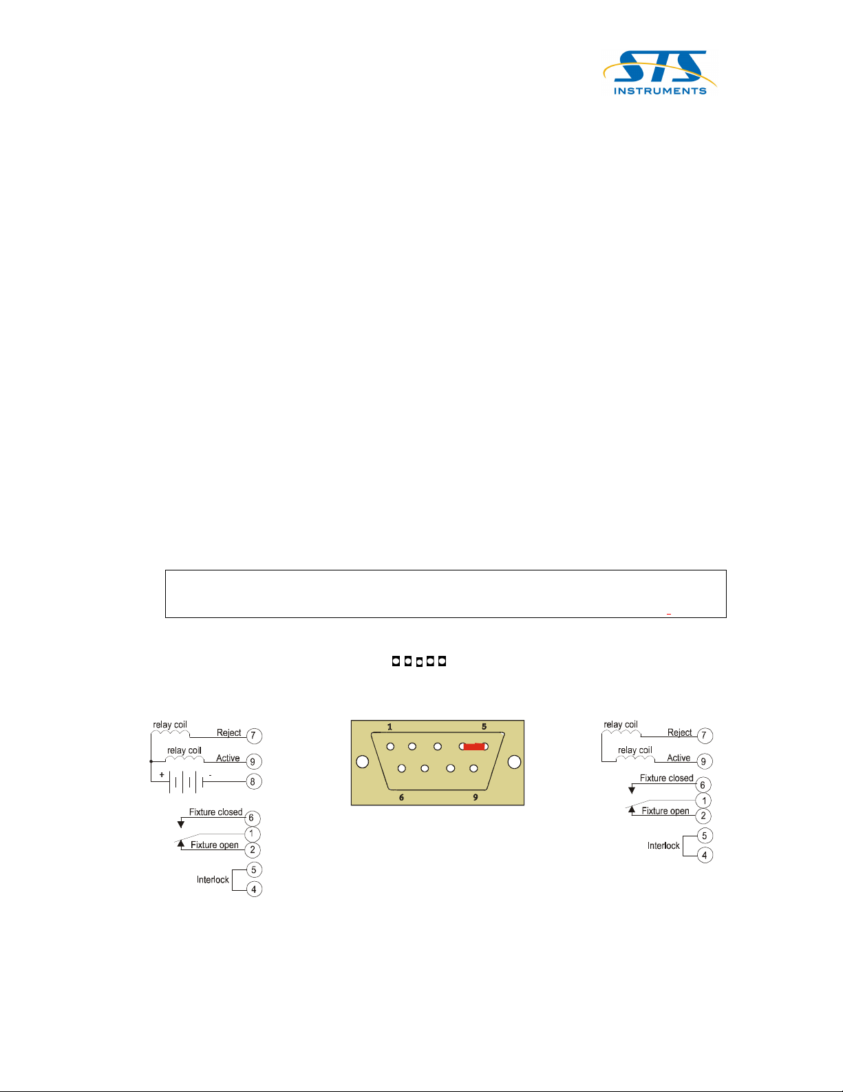
12. REMOTE INTERFACE – (back panel)
13. MODULAR LINE CORD ASSEMBLY – (back panel)
THE INTERFACE CONNECTOR MUST BE PLUGGED INTO
THE SOCKET BEFORE TESTER WILL OPERATE
.
PLUG WIRING
WIRING WIEW SHOWN
9-PIN DSUB PLUG
150-766-002
Customer Interface 1660
(with external power supply)
Customer Interface 1660
(with internal 5 volt supply)

Diagrams and descriptive information on this page are intended to be
illustrative only and not specific instructions. To obtain optimum
performance in any particular application, a certain amount of
experimentation is generally required to establish the proper test
configuration, parameters and operating procedure.
In addition, internal modifications in the Surge Tester are sometimes
needed to obtain peak performance for specific applications. For high
production applications: particularly, those involving more than one test,
automatic sequencing equipment is available. This includes standard
systems for testing armatures, stators, and typical coils. Consult factory
for assistance. (Most common used methods are A & B) Please note that
lead modification may be required for some of the following testing
configurations.
______________________________________________________
A. IRON CORE WINDINGS SUCH AS TRANSFORMERS,
CHOKES, RELAYS, ETC., FOR OPENS, SHORTS AND
GROUNDS.
NOTES:
1. This setup will detect turn-to-turn shorts in any of the windings.
To check unused windings for opens, simply short leads and retest,
tester will indicate short unless winding is open.
2. If ground test and winding-to-winding shorts test is required, add
dotted ground circuit. Multiple tests should be made with winding
leads reversed between the tests.
______________________________________________________
B. SIMPLE WINDINGS, SUCH AS MOTOR AND
GENERATOR FIELDS, FOR OPENS, SHORTS AND
GROUNDS.
NOTES:
1. This technique will detect turn-to-turn and layer-to-layer shorts in
salient pole windings and in some types of distributed windings.
2. If ground test is desired, add dotted ground circuit and make two
tests with winding leads reversed between the tests.
_________________________________________________
C. MULTIPLE WINDINGS, SUCH AS MOTOR AND
GENERATOR STATORS, FOR OPENS, SHORTS AND
GROUND.
NOTES:
1. Individual tests should be made on each winding, with connections
changed between tests as shown.
2. If coupling between windings is insufficient to detect all winding
faults, additional tests should be made with winding leads
reversed.
3. If ground test is desired, add dotted ground circuits.
4. If windings are identical, calibration resistors may be omitted.
D. DISTRIBUTED WINDINGS, SUCH AS
POLYPHASE AND SPLIT PHASE STATORS
FOR OPENS, SHORTS AND GROUNDS.
NOTES:
1. Two tests should be made with lead 1 and 3
interchanged between tests.
2. If windings are not identical, calibration resistor may
require change when leads are interchanged.
3. If ground test is desired, add dotted ground circuit.
_________________________________________________
E. MOTOR AND GENERATOR ARMATURES FOR
POOR
CONNECTIONS, OPENS AND SHORTS.
NOTES:
1. Armature must be indexed or rotated during test.
_________________________________________________
F. MOTOR AND GENERATOR ARMATURES FOR
OPENS, SHORTS AND GROUNDS.
NOTES:
1. Armature must be indexed or rotated during test.
2. Pick off contacts must not be staggered in relation to
commutator bars.
3. This test especially sensitive to insulation weakness.
4. If ground test desired, add core contact and dotted
ground circuit.
TYPICAL TEST TECHNIQUES
Page 6

Page 7
PRODUCTION TEST SETUPS
THE INTERFACE CONNECTOR MUST BE PLUGGED INTO
THE SOCKET BEFORE TESTER WILL OPERATE
.
Using a typical known “good” part, set up unit according to the following procedure:
A. Adjust Sensitivity Full CW, Voltage Full CCW, Balance approximately midway, set
Limit Controls to 9.9, and set Dwell Timer for desired time.
B. Connect part per technique selected.
C. Press and hold Test Switch and raise voltage to approximately ¼ the value to be used.
D. Adjust Balance Control for zero meter reading.
E. Increase Voltage to desired value.
F. Readjust Balance Control as necessary to maintain zero meter reading.
G. Release Test Switch.
The unit is now balanced with the sample good part, and operating at minimum
sensitivity.
To determine proper sensitivity setting, test parts with known defects, as well as a
representative group of good parts, and note deviation readings obtained. Then
adjust sensitivity control and balance, as necessary, to obtain a usable deviation (at
least 0.1) with a “minimum defect” and a nominal reading of zero with good parts.
Selection and preservation of suitable “good” and “defective” samples will simplify
repeat setups.
In the absence of suitable defective parts, it is suggested that a synthetic defective
part be produced by taking a known good part and adding a single shorted loop
equivalent to 1% of the turns of the part. The ends of the loop should be soldered to
ensure good conductivity and should fit snugly around the coil. The loop NEED
NOT be in electrical contact with the remainder of the winding. The inductive effect
will be sufficient to simulate a defect.
From the pattern of readings obtained, establish acceptance limits and in the case of
Series 1660 equipment, adjust limit controls accordingly.
After completion of setup, operating personnel should be carefully instructed in the
test procedures and properly cautioned regarding any potential hazards involved.
Safety training of the operator is an essential part of the production test setup.
CAUTION: (RISK OF ELECTRIC SHOCK)
Be sure tester installation is in accordance with
instructions. The actual production test setup should then
be made only by qualified technical personnel.

Page 8
REPEAT SETUPS
Repeat setups are most easily accomplished using “good” and “defective” samples
selected during the initial setup. If these are available, the repeat setup becomes a matter
of simply adjusting the various switches and controls to the required values and then
adjusting the balance control with the good sample, and the sensitivity control with the
defective sample.
Checking back and forth two or three times with the two samples will result in a setup
duplicating the original … that is, showing a nominal reading of zero with a good part
and the original deviation with the defective part.
Alternatively, repeat setups can be made simple by returning all controls, including the
balance and the sensitivity controls, to their original position. If this approach is used, it is
still a wise idea to check the balance with a known good part.

Page 9
TEST PROCEDURES
Check dwell timer for desired setting:
Production Test Procedures are quite simple:
A. PRESS & RELEASE TEST SWITCH - If meter reading exceeds limits established in
setup procedure, defects exist. If not, the part is acceptable. To check inactive
windings for opens, simply short circuit leads of these windings, one at a time, and
note if meter reads downscale. If not, winding is open.
B. With Series 1660 units, operator observance of the meter is unnecessary. Simply
operate test switch. After about 1/2 second, for defective parts, the reject lamp will
come ON and the buzzer will sound.
C. As an aid to the operator, it is suggested that typical samples of various defects be
kept available for use in refreshing the memory.
D. It is also important that the operator be familiar with any heating effects that may
occur in the product so as to be able to distinguish these effects from defects.
E. In some cases, reverse readings are an indication of acceptance; for example, the
checking of armatures for opens, per Technique E. The operator should, of course,
be properly instructed in regard to such situations.
CAUTION:Test Procedures should be carried out only by
personnel who have been thoroughly instructed as to the
nature of the procedure, the hazards involved, and the
necessary safety precautions.
CAUTION: D
well Time
can increase safety hazards.
The operator should be instructed that the TEST light
must be dark before removing clip leads. Set Dwell
Time to minimum necessary.

Page 10
Maintenance
Routine maintenance should include the following:
1. Function Check
At least once per shift verify calibration by the methods described in the
“Installation and Safety” on page 7.
2. Safety Inspection
A. Daily – Check test leads for damage. Leads should be inspected for cracks or
deterioration. Rear panel terminals should be inspected for excessive wear,
cracks or loose components.
B. Monthly – Check line cord on tester for damage, deterioration and ground
lead integrity. Check line receptacle for ground integrity.
3. Annual Service
All testers should be returned to the factory at least once per year for calibration
and certification.
Replacement Parts List; Model 1660
Part Number Qty. Description
102-051-903 1 HV Dual Test Lead, Blue & Yellow Plug
102-055-909 1 HV Single Test Lead, Black Plug
150-822-002 2 Fuse, 3.15A 250V GDC 5x20mm Time Lag
350073 1 Lamp, Reject 327 28V
350098 1 Lamp, HV On 382 14V.08a
330081 1 Red P/B Lens & Lamp Holder
330082 1 White P/B Lens & Lamp Holder
995-028-901 1 Safety Interlock Plug Assy., 9-Pin
Optional Parts List; Model 1660
Part Number Qty. Description
150-766-002 1 D-Connector, 9-Pin
150-787-003 1 Housing, D-Connector, 9-Pin
WARNING: (RISK OF ELECTRIC SHOCK)
DO NOT REMOVE COVER. NO USER SERVICEABLE PARTS
INSIDE, PLEASE REFER SERVICIING TO QUALIFIED SERVICE
PERSONNEL.

Page 11
REPAIR SERVICE
Complete calibration and repair services are offered at our Ardmore, Oklahoma manufacturing
facility. Calibrations are to original factory specifications and are traceable to National
Standards. A certificate of conformance accompanies each repaired tester.
A Return Material Authorization (RMA) number must be obtained from STS Instruments before
returning any instrument for repair. Please contact STS at 1-800-421-1921, 580-223-4773 or
(including insurance) for the return of the instrument to STS must be prepaid by the customer.
Testers sent for repair should be shipped prepaid and insured to:
STS INSTRUMENTS
Attn: RMA #
801 Hailey Street
Ardmore, Oklahoma 73401
Inside the container with the tester, put the name and telephone number of someone to contact if
the Service Dept. has questions regarding the repair and someone to advise of billing. Please
indicate your “ship to” address – no P.O. Boxes, please.
Subject to weight restrictions, testers are normally returned to the customer via UPS ground with
the actual shipping charges prepaid and added to the invoice. Premium shipping and alternate
carriers can be provided upon customer request. Freight charges will vary according to the
method/carrier specified.
Factory service is based upon an hourly rate with a one-hour minimum charge per tester. Parts
needed to bring the testers back to factory specifications are extra.
Altered testers cannot be certified. All non-STS parts will be removed and the customer charged
to bring the tester back to original factory specifications before calibration will be attempted.
From time to time testers are received that may be inadvisable to repair due to age, condition
and/or obsolescence of parts from suppliers. Customers are notified.
Non-warranty repairs carry a limited warranty of 90 days on services and replacement parts only.
Defects in our repair work or any parts replaced will be corrected at no charge if the defect occurs
within 90 days from shipment from our factory.
If difficulty arises during the 90-day period that is due to a secondary defect, which could not
normally be detected during the original service procedure, it will be repaired and a charge made
only for parts used.
WARNING:
Field repairs, oth
er than routine replacement test probe
assemblies and fuses are not recommended due to the risk of high
voltage shock. It is recommended that defective equipment be
returned to the factory for repair.

Page 12
1 YEAR LIMITED WARRANTY POLICY
All products are covered by our standard limited warranty: Your new instrument is
warranted to be free from defects in workmanship and material for a period of (1) year from date
of shipment and we will repair or replace any such product we find to be so defective upon its
prepaid return to us. This warranty is void if the product has been tampered with, or subjected to
gross misuse, and is exclusive of all others, expressed or implied. In case products of other
manufacturers are specified as an option by the customer, the warranty of that manufacturer will
apply to such items, and our responsibility is limited to assisting the customer in filing warranty
claims with the manufacturer responsible. In the event that the prepaid return of an instrument to
our Ardmore, Oklahoma plant is impractical and the customer desires on-site warranty, we expect
payment for the actual incurred travel and out-of-factory expense of our factory representative.
A Return Authorization (RA) must be obtained from STS Instruments before returning
any instrument for warranty service. Please contact STS at 1-800-421-1921, (580) 223-4773 or
is important that the instrument is packed in its original container for safe transport. If the
original container is not available, please contact our customer support center for proper
instructions on packaging. Damages sustained as a result of improper packaging will not be
honored. Transportation costs (including insurance) for the return of instrument for warranty
service must be prepaid by the customer.
Except as provided herein, STS Instruments makes no warranties to the purchaser of this
instrument and all other warranties, expressed or implied (including, without limitation,
merchantability or fitness for a particular purpose) are hereby excluded, disclaimed and waived.
Any non-authorized modifications, tampering or physical damage will void your
warranty. Elimination of any safety systems will void this warranty. This warranty does not
cover batteries or accessories not of STS Instruments manufacture. Parts used must be parts that
are recommended by STS Instruments as an acceptable specified part. Use of non-authorized
parts in the repair of this instrument will void the warranty.
STS Instruments certifies that this instrument was calibrated using standards that are
traceable to the National Institute of Standards and Technology (NIST). Most safety compliance
agencies such as UL recommend that your instrument be calibrated on a twelve-month cycle.

Page 13
DECLARATION OF CONFORMITY
Manufacturer’s Name:
STS Instruments, Inc.
Manufacturer’s Address:
801 Hailey Street
Ardmore, Oklahoma 73401
USA
Declares that the product:
Surge Tester
Model Name:
Model 1660
Conforms to the directives and standards identified in this declaration
EU Directives:
89/336/EEC
Electromagnetic Compatibility Directive, amended by 93/68/EEC
73/23/EEC
Low Voltage Directive
Standards:
EMC: EN 61000-4-2: 1995 “Electromagnetic Discharge immunity test”
EN 61000-4-3: 1998 “Radiated, radio frequency, electromagnetic field immunity test”
EN 61000-4-4: 1995 “Electrical Fast Transient/burst immunity test”
EN 61000-4-5: 1995 “Surge immunity test:
EN 61000-4-6: 1996 (Incorporating Amendment No. 1) “Immunity to Conducted disturbances,
inducted by radio-frequency fields”
EN 61000-4-11: 1994 “Voltage dips, short interruptions and voltage variations immunity test”
EN 61326 (CISPR 16: 1993 “Specification for radio disturbance and immunity measuring
apparatus and methods”)
Safety: EN 61010-1: 2001 “Safety requirements for electrical equipment for measurement,
control, and laboratory use”
The technical documentation required to demonstrate that the product meets the requirements of the
directives listed in this declaration is available for inspection by the relevant enforcement authorities.
CE mark first applied:
2004
Table of contents
Other STS Test Equipment manuals


