4
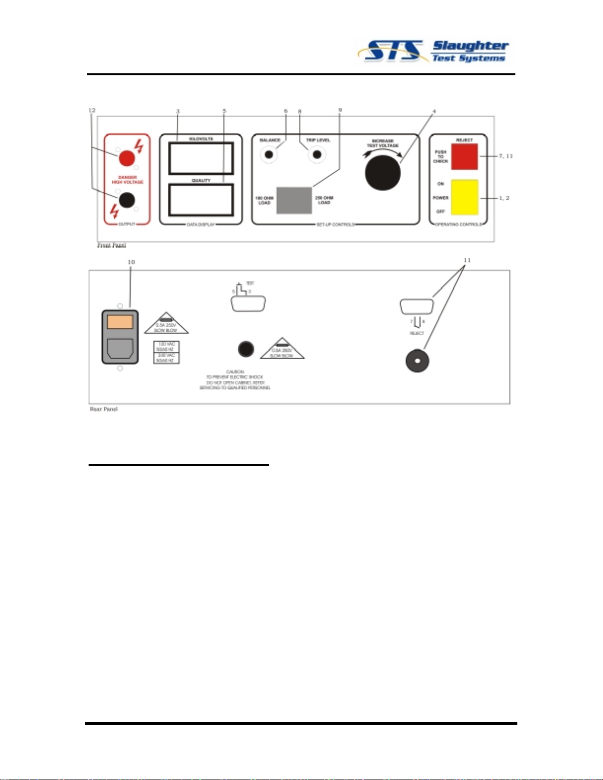
Controls and Indicators
Functions of the various Controls and Indicators are shown in fig. 1 on the next page and
described as follows:
1. Power Switch – The rocker power switch is used to turn the unit On and Off.
2. Pilot Light – Contained within the Power switch is a Pilot Lamp, which lights
when the unit is turned On.
3. Voltmeter – The digital Voltmeter provided on this unit monitors the actual test
voltage at the output terminals of the unit at all times. This is a true peak reading
meter and indicates the actual peak voltage appearing at the output terminals of
the unit. Note that when a load is placed on the output terminals, the voltmeter
indication may change, depending on the type of load involved. In the case of a
short circuit, this voltage may fall practically to zero. However, the tester will still
be On, producing test voltage, which is absorbed within the unit. NOTE. The
testing voltage is a NEGATIVE voltage and the voltmeter will display a negative
sign (-).
4. Voltage control – Voltage control provided on this unit is used to adjust the
actual test voltage. Clockwise rotation increases test voltage.
5. Quality Meter – The digital Quality Meter monitors loading produced by the
workpiece. It is calibrated in arbitrary units on a scale of 0 to ±1000. As loading
increases, due to defects or moisture, the indication on this meter will read down-
scale as an increasingly larger negative number.
6. Balance Control – This control is used to balance quality meter circuitry to
correspond to the actual operating conditions. Normally, it is adjusted under no-
load conditions to provide a 000 reading on the leakage meter.
7. Check Button – The Check Button is used to verify that the leakage meter
circuitry is operating normally. After the voltmeter has been properly balanced at
2.00KV, operation of the check button under no-load conditions should produce a
leakage meter reading of approximately –600. When the button is released, the
leakage meter reading should return to the 000 balance condition.
8. Trip Level – This control is used to set the desired reject level.
9. Sensitivity Select Switch – This rocker switch allows the selection of two levels
of sensitivity to match the minimum impedance characteristics of different battery
element testing requirements.
10. Modular Line Cord Assembly – The Modular Line Cord Assembly is located on
the rear of the tester. It consists of the Socket/Filter section, which is black and
permanently mounted to the tester, the removable Line Cord, and the removable
Fuse Drawer, which is tan.
11. Reject Indicator(s) – The Model 1652 has three (3) Reject Indicators; on the
front panel, a Red illuminated button, on the rear panel, an Audible Tone and a 9-
pin D-sub connector provides a Dry Contact Closure when a reject occurs.
12. High Voltage Connectors – Two (2) High Voltage connectors are provided on
the front panel. Polarity should be observed when connecting the leads. The
black socket is referenced to ground.