STUCCHI EPN0324 User manual
A.A.G. STUCCHI s.r.l. u.s.
Via IV Novembre 30/32
23854 Olginate (LC) - ITALY
Ph. +39-0341-653111
Fax +39-0341-653250
www.aagstucchi.it
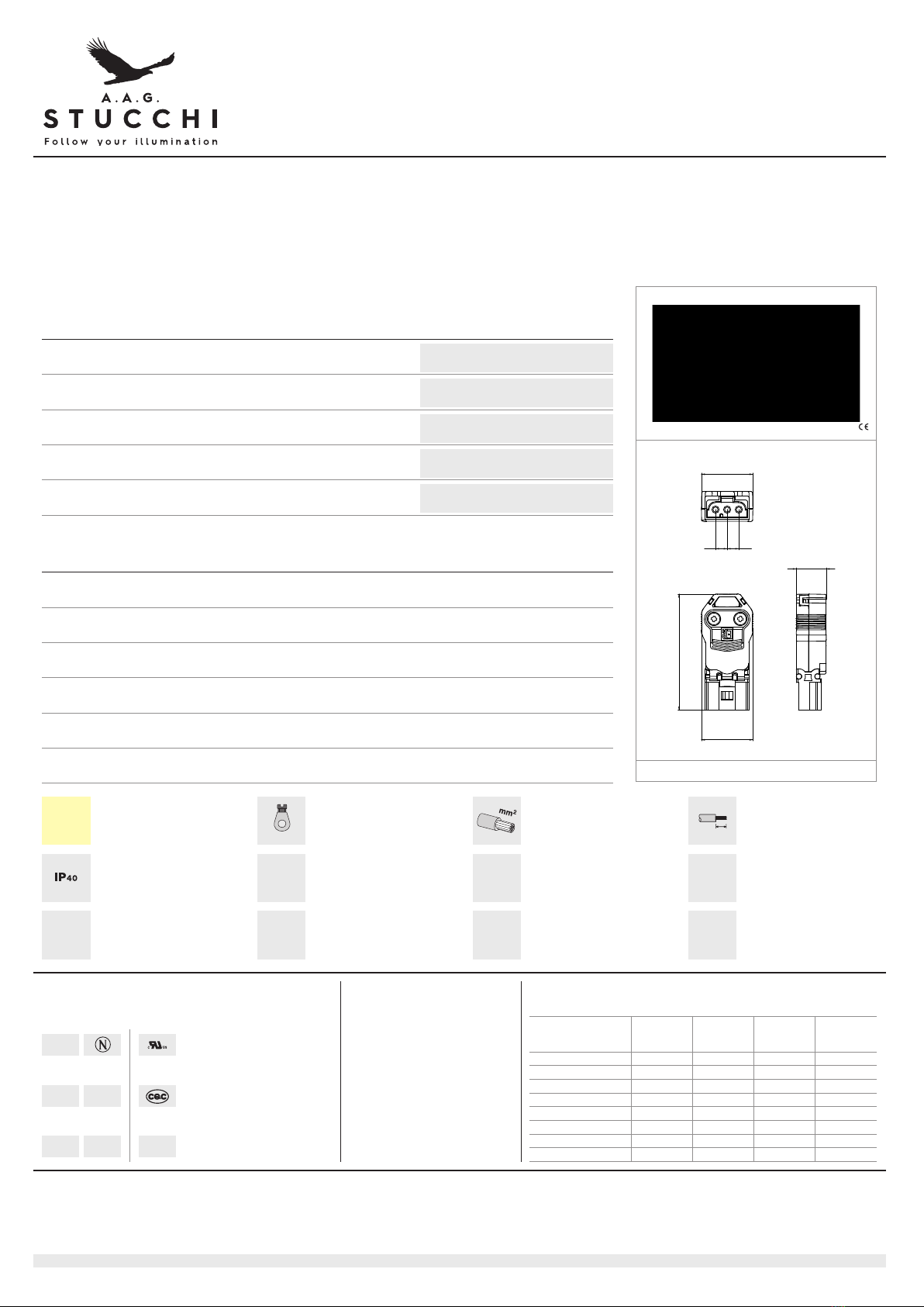
EPN0324 EPN0325
SPINE DI CONNESSIONE CON SISTEMA DI AGGANCIO (MINI)
CONNECTION PLUGS WITH LOCKING SYSTEM (MINI)
Dati tecnici
Technical data
- Poli
- Poles
2P+E
- Corrente e tensione nominale
- Rated cu ent and voltage
16A-250V
- Temperatura massima di funzionamento (IEC)
- Maximum ope ating tempe atu e (IEC)
T100
- Grado di protezione
- P otection index
IP20
Caratteristiche
Cha acte istics
— Corpo in poliammide ...4= nero ...5= bianco
— Polyamide body ...4= black ...5= white
— Contatti in ottone argentato
— Silve plated b ass contacts
— Marchiatura: L - T - N
— Ma king: L- E - N
5.3 5.3
23.4
23.4
52.7
13.6
Con/With: EPN0334; EPS0334
senza fissaggio
without fixing
serrafilo con vite e morsetto
sc ew te minals
sezione conduttore flessibile
section of the flexible
conducto
spelatura cavetti flessibili
flexible wi es st ipping
protetto IP40 uando
accoppiato
IP40 p otected when plugged
in
EPN0325
EPN0324
P oduct efe ences Net weight pe bag pe box pe ca ton
Codice prodotti Peso netto per sacco per scatola per cartone
Art. g n° pz n° pz n° pz
Pesi e confezioni
Weights and packaging
Diretti e Europee
Eu opean di ectives
Marchi di qualità
Quality ma ks
Conforme "RoHS"
"RoHS" compliant
Non soggetto alla "RAEE"
Not subject to "WEEE"
600V - max T110°C - AWG14 SOL/STR 15A;
AWG16 SOL/STR 10A; AWG18 SOL/STR 7A
(WORK IN PROGRESS)
Note - I connettori EPCOM sono conformi alla EN/IEC61535+A1 solo se usati con dispositivo di aggancio.
Notes - EPCOM connecto s a e compliant with EN/IEC61535+A1 only when used with locking device.
6-03-2019 PAG 1
0,75-1,5 8
A.A.G. STUCCHI s.r.l. u.s.
Via IV Nove bre 30/32
23854 Olginate (LC) - ITALY
Ph. +39-0341-653111
Fax +39-0341-653250
i fo@aagstucchi.it
www.aagstucchi.it
1. I connettori sono intesi per connessione e disconnessione
esclusiva ente in assenza di tensione
2. I test previsti nella nor a EN61535+A1 sono stati eseguiti sui cavi
3/4/5G 1,5/2,5 H05VV-F a I connettori EPc possono essere utilizzati
con altri tipi di cavo a richiesta co e Halogen free=H05Z1Z1-F,
Go a=H07RN-F, Silicone=H05SS-F (in Spagna=RZ1-K);
3. I connettori non sono adatti per l’installazione in aree facil ente
accessibili
4. ELETPLAST infor a che i prodotti EPc, quando questo è verificato e
certificato da pri ari istituti di qualità (es. NEMKO, VDE), sono
co patibili con prodotti si ilari di altri produttori.
ELETPLAST è disponibile a infor are sui archi e i odelli per cui è
stata certificata la co patibilità.
5. I connettori ELETPLAST non sono da intendersi co e sostituzione delle
spine e prese do estiche nazionali o prolunghe con adattatori ultipli.
6. I connettori della serie EPCOM sono confor i alla nor a
EN61535+A1 solo se provvisti di dispositivo d’aggancio.
Pri a di iniziare qualsiasi opera, l’installatore deve assicurarsi che
l’interruttore generale sia posizionato su “OFF” per prevenire ogni
possibile rischio elettrico.
Questi prodotti devono essere installati da un elettricista qualificato a
cablati in confor ità alle nor e sul cablaggio IEE.
VITI
Coppia di serraggio delle viti:
LUNGHEZZA SGUAINATURA CAVO ED OPZIONI PER
COPERTURA BLOCCACAVO
EPC3,4,5 co bloccacavo:
3P: 27 (33 PE) - ø7-8.3 (versione standard),
ø9-10.5 (versione M, disponibile a richiesta);
4P: 29 (36 PE) - ø8.4-10.5 (standard version),
ø10.0-12.0 (versione M, disponibile a richiesta);
5P: 31 (39 PE) - ø9.5-11.6 (standard version),
ø13.0-14.0 (versione M, disponibile a richiesta)
EPN3,4,5
3P: 27 (35 PE) - ø7.5-10.5 (ø6-9,5 con EPNR8)
4P: 32 (40 PE) - ø7.0-12.5
5P: 37 (45 PE) - ø9.5-14
EPN2, EPS2 Mi i: 21 - ø5.5-8
EPN3, EPS3 Mi i: 20 (24 PE) - ø6-9
EPN5, EPS5 Mi i: 30 (38 PE) - ø6-11
1. Insta ation coup ers are intended for connection and disconnection
without oad, on y;
2. EN61535+A1 Test has been made on the 3/4/5G 1,5/2,5 H05VV-F but
EPc connectors can be used a so with other cab es types are upon
request as Ha ogen free=H05Z1Z1-F, Rubber=H07RN-F, Si icon=H05SS-F
(cab e for Spain=RZ1-K);
3. This insta ation coup er is not suitab e for insta ation in readi y
accessib e areas;
4. ELETPLAST informs the insta er that EPC Products when verified and
certified by a qua ity brand testing company as (NEMKO or VDE)
accept the compatibi ity with simi ar products made by other
manufacturer. ELETPLAST verified the attendibi ity test wi inform the
customer what are the brands and items approved.
Any other connection with simi ar products made by other brands
companies are not accepted nor warranted by EP;
5. E etP ast’s insta ation coup er systems are not rep acements for the
nationa domestic p ug and socket out et-system;
6. EPCOM connectors are comp iant with EN61535+A1 on y when used
with ocking device.
Before commencing any e ectrica work, ensure the mains iso ator on
the consumer unit / fuse borad is in the ‘OFF’ position, to prevent the
possibi ity of e ectric shock.
These products shou d be insta ed by a qua ified e ectrician, and wired
in accordance with the IEE Wiring Regu ations.
SCREWS
Screws torque:
DISMANTLING LENGTH, STRAIN RELIEF COVERS
OPTIONS
EPC3, ,5 with strain relief:
3P: 27mm (33mm PE) - 7-8.3mm (standard version),
9-10.5mm (M version, available on demand);
4P: 29mm (36mm PE) - 8.4-10.5mm (standard version),
10.0-12.0mm (M version, available on demand);
5P: 31mm (39mm PE) - 9.5-11.6mm (standard version),
13.0-14.0mm (M version, available on demand)
EPN3, ,5:
3P: 27mm (35mm PE) - 7.5-10.5mm ( 6-9,5mm with EPNR8)
4P: 32mm (40mm PE) - 7.0-12.5mm
5P: 37mm (45mm PE) - 9.5-14mm
EPN2, EPS2 Mini: 21mm - 5.5-8mm
EPN5,EPS5 Mini: 20mm (24mm PE) - ø6-9mm
EPN5,EPS5 Mini: 30mm (38mm PE) - ø6-11mm
ISTRUZIONI DEL COSTRUTTORE
MANUFACTURER’S INSTRUCTIONS
24-03-2017 PAG 2
Marchio/Mark 1,5 mm2solid 2,5 mm2solid
10 A 20A
10 A 20 A*
*For Canada 15 A
EPN2 EPS2 EPC3, 4, 5 EPN3, 4, 5 EPS3, 4, 5
M3 per conduttori/M3 conductors 0,5 N 0,5 N 0,5 N 0,5 N
M3 per copertura/M3 cover 0,3 N 0,6 N 0,6 N 0,6 N
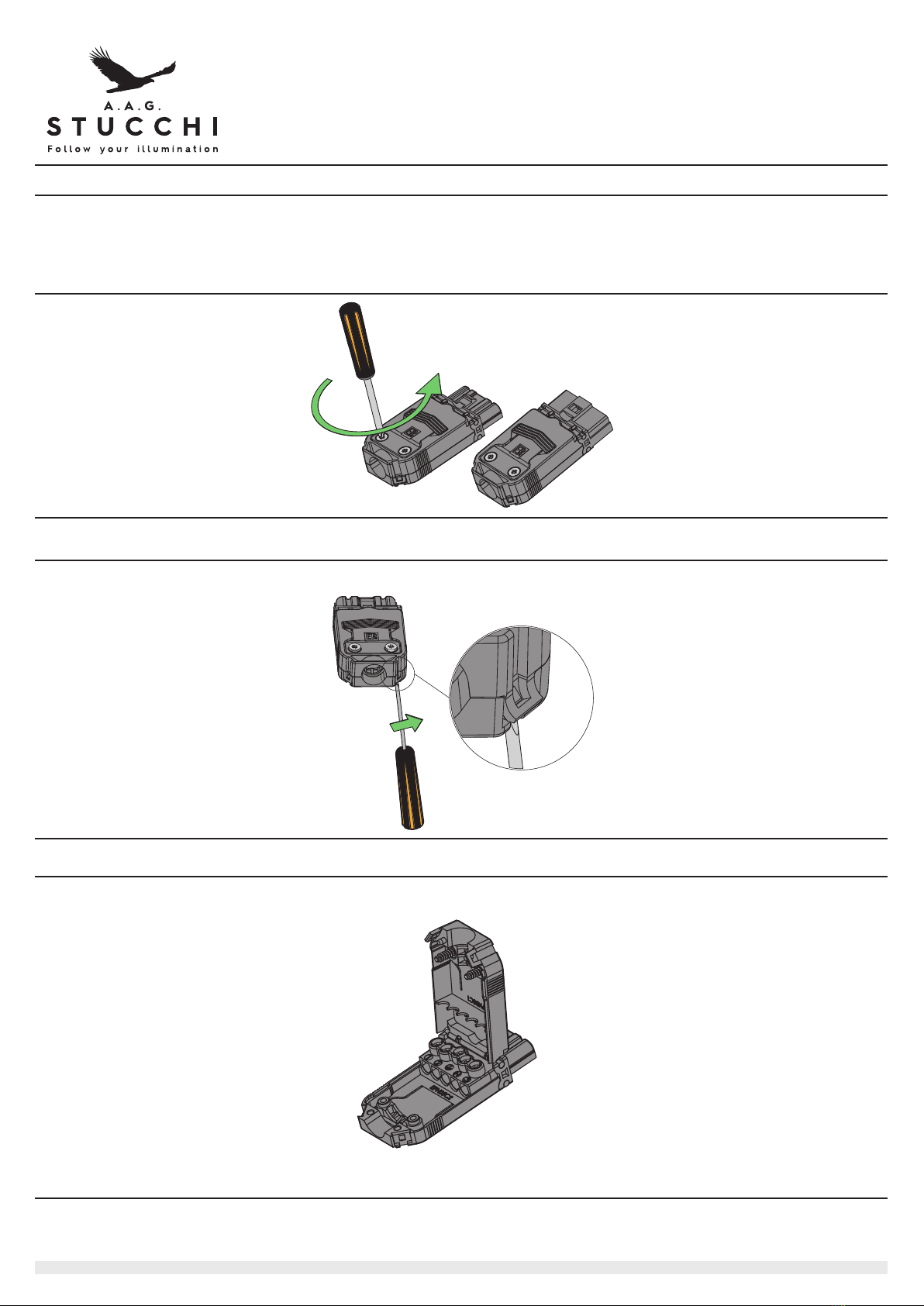
Svitare le viti del co erchio con un cacciavite a stella.
Piega l’aggancio er liberarlo dal gancio di chiusura
A ri il co erchio.
Unscrew the cover screws with a crosshead screwdriver.
Bent the fastening to free it from the closing hook:
O en the u er cover.
A.A.G. STUCCHI s.r.l. u.s.
Via IV Novembre 30/32
23854 Olginate (LC) - ITALY
Ph. +39-034 -653
Fax +39-034 -653250
info@aagstucchi.it
www.aagstucchi.it
ISTRUZIONI DEL COSTRUTTORE
MANUFACTURER’S INSTRUCTIONS
15-06- 017 PAG 3
Presa / Socket
Spina / Plug

Pre ara il cavo con la sguainatura indicata.
Inserisci i conduttori nei contatti metallici e serra le relative viti.
Chiudi il co erchio e blocca il cavo serrando le relative viti.
Esegui le stesse o erazioni er la resa
Connetti la resa e la s ina come indicato in figura.
Verifica che il ganco di chiusura stia lavorando correttamente.
Pre are the cable with the showned stri ing.
Insert conductors inside the brass contacs holes and screw the
screws for cabling.
Close the u er cover and com ress the cable by screwing the
two screws.
Do the same o erations for the lug and then a roach and align
lug and socket as shown by arrows
Be shure the hook is closed and works correctly.
A.A.G. STUCCHI s.r.l. u.s.
Via IV Novembre 30/32
23854 Olginate (LC) - ITALY
Ph. +39-034 -653
Fax +39-034 -653250
info@aagstucchi.it
www.aagstucchi.it
15-06- 017 PAG 4
30
38
20
24
21
8
2P
3P
5P
8
8
8
8
This manual suits for next models
1
Other STUCCHI Cables And Connectors manuals


