STUCCHI 3701/V User manual

A.A.G. STUCCHI s.r.l. u.s.
Via IV Novembre 30/32
23854 Olginate (Lc) - ITALY
Ph. +39-0341-653111
Fax +39-0341-653250
www.aagstucchi.it
PAG 1
11-03-2021
Marchi di qualità
Quality marks
Note
Direttive Europee
European directives
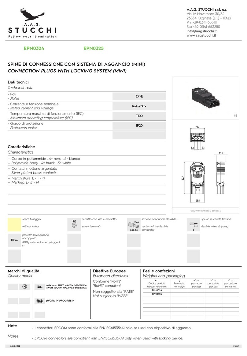
Dati tecnici
Technical data
Caratteristiche
Characteristics
Notes
600V-15A(AWG14) 10A(AWG16)
7A(AWG18) T105
- La temperatura massima di funzionamento T é la massima temperatura ambiente alla quale il connettore può funzionare con il valore di
corrente nominale indicato (EN/IEC61984). Limite di temperatura inferiore / superiore é: -10 °C / +150 °C (EN/IEC61984).
- The maximum operating temperature T is the maximum ambient temperature for the connector working at the rated current value
indicated (EN/IEC61984). Temperature lower/upper limits: -10 °C / +150 °C (EN/IEC61984).
- Poli
- Poles
2P+E
16A-250V
T120
IP66/IP68
III / 2
Conforme “RoHS”
“RoHS” compliant
senza fissaggio
without fixing
rigid and flexible with ferrule wires
stripping
spelatura cavetti rigidi e flessibili con
fascetta
serrafilo con vite e morsetto
screw terminals
suitable for impulse ignition voltage
up to...
adatto per tensione di accensione
ad impulsi fino a...
sezione conduttore flessibile con
fascetta
section of the flexible conductor
with ferrule
protetto IP66/IP68 (3m/2h)
IP66/IP68 protected (3m/2h)
sezione conduttori rigidi
rigid conductor section
3701/V-N
3701/V
24,8
24,8
200
200
500
500
Pesi e confezioni
Weights and packaging
S-3700/121
3700/C...
5kV
7-8
1-2,5
1-2,5
SPINA DI CONNESSIONE PROTETTA
PROTECTED CONNECTION PLUG
Art.
Codice prodotti
Product references
g
Peso netto
Net weight
n° pz
per sacco
per bag
n° pz
per scatola
per box
n° pz
per cartone
per carton
Con/With: 3702/...
- Corrente e tensione nominale
- Rated current and voltage
- Temperatura massima di funzionamento (IEC)
- Maximum operating temperature (IEC)
- Grado di protezione
- Protection index
- Cat. sovratensione / Grado di inquinamento
- Impulse withstand cat. / Pollution degree
— Contatti in ottone argentato
— Silver plated brass contacts
...V= grigio chiaro ...V-N= nero
...V= light grey ...V-N= black
— Corpo in poliammide grigio chiaro
— Light grey polyamide body
3701/V
3701/V-N

A.A.G. STUCCHI .r.l. u. .
Via IV Nove bre 30/32
23854 Olginate (LC) - ITALY
Ph. +39-0341-653111
Fax +39-0341-653250
info@aag tucchi.it
www.aag tucchi.it
AVVERTENZE E ISTRUZIONI DI MONTAGGIO
CONNETTORI PROTETTI IP66/IP68 2-3 POLI
I connettori devono essere collegati al cavo in assenza di tensione.
Il cavo di ali entazione deve se pre essere collegato al
connettore presa 3702/… .
I connettori per fissaggio a parete art. 3701/A… e 3702/A… hanno
il serrafilo auto atico a 2 fori (0,5-2,5 2) che accetta due cavetti
per ogni polo: si devono utilizzare cavetti di sezione adeguata alla
corrente per l’eventuale collega ento passante e si possono
utilizzare cavetti di sezione inferiore per derivare l’ali entazione
dell’apparecchio di illu inazione.
I connettori art. 3701/… e 3702/… non devono essere utilizzati co e
sostituzione di prese e spine do estiche.
CAVI UTILIZZABILI:
-FG7OR: 2X1.5 2 ; 2x2,5 2; 3X1.5 2 ; 3x2,5 2
-FROR: 2X1.5 2 ; 2x2,5 2; 3X1.5 2 ; 3x2,5 2
-H05VV-F: 2x2,5 2; 3X1.5 2 ; 3x2,5 2
-H07RN-F: 2x1 2; 2x2,5 2; 3X1.5 2 ; 3x2,5 2
-SIHF: 2x2,5 2; 3x2.5 2
-AWG14: 2X; 3X
-AWG16: 2X; 3X
-AWG18: 2X; 3X
CORRETTO ACCOPPIAMENTO CORPO/GUSCIO
3701/A...: corpo spina (1) + guscio con pin di fissaggio (2)
3701/V...: corpo spina (1) + guscio con pin di fissaggio (2) e bloccacavo
3702/A...: corpo presa (3) con finestre di aggancio (4)
3702/V...: presa (3) con cave di fissaggio (4) e bloccacavo
WARNINGS AND MOUNTING INSTRUCTIONS FOR
IP66/IP68 2-3 POLES CONNECTORS
The connectors ust be connected to the cable out of voltage.
The supply cable ust be always connected to the connection
socket. 3702/… .
Connectors for the panel ounting art. 3701/A… and 3702/A…
have 2 holes (0,5-2,5 2) push wires ter inals which accept
two wires for each pole: wires with a suitable section for the
current involved ust be used for the eventual passing through
connection and wires with reduced section can be used to
supply the internal circuit of the lighting fitting.
The connectors art. 3701/…, 3702/… ust not be used as
replace ent of do estic sockets and plugs.
SUITABLE CABLES:
-FG7OR: 2X1.5 2 ; 2x2,5 2; 3X1.5 2 ; 3x2,5 2
-FROR: 2X1.5 2 ; 2x2,5 2; 3X1.5 2 ; 3x2,5 2
-H05VV-F: 2x2,5 2; 3X1.5 2 ; 3x2,5 2
-H07RN-F: 2x1 2; 2x2,5 2; 3X1.5 2 ; 3x2,5 2
-SIHF: 2x2,5 2; 3x2.5 2
-AWG14: 2X; 3X
-AWG16: 2X; 3X
-AWG18: 2X; 3X
RIGHT BODY/SHELL MOUNTING
3701/A...: plug body (1) + shell with fixing pins (2)
3701/V...: plug body (1) + shell with fixing pins (2) and gland
3702/A...: plug body (3) with openings for cla ping (4)
3702/V...: socket (3) with holes for fixing (4) and gland
01/04/2015 PAG. 2
2P 2P+T
1
2
2
2
2
2P 2P+T
1
2
2
2
2
2P 2P+T
4
3
4
4
2P 2P+T
4
4
3
4

A.A.G. STUCCHI .r.l. u. .
Via IV Nove bre 30/32
23854 Olginate (LC) - ITALY
Ph. +39-0341-653111
Fax +39-0341-653250
info@aag tucchi.it
www.aag tucchi.it
ISTRUZIONI DI MONTAGGIO PER CONNETTORI CON
SERRAFILO A VITE
Lunghezze di sguainatura del cavo e spelatura dei conduttori
Connessione dei conduttori
Inserire il cavo (4) attraverso il dado bloccacavo (1), la
guarnizione (2) e il corpo (3).
Collegare i conduttori ai serrafili a vite del frutto (5) ed inserirlo
nel corpo fino a quando i ganci scattano nelle apposite
aperture (figure Ae B).
ATTENZIONE L’accoppia ento tre le due parti (3, 5) è possibile
solo in una posizione.
Ruotare i due co ponenti fino a quando viene per esso
l’inseri ento (i ganci devono essere allineati alle relative finestre di
aggancio).
MOUNTING INSTRUCTION FOR CONNECTORS WITH
SCREW TERMINALS
Cable and conductors stripping lengths
Wires connection
Insert the cable (4) through the nut of the gland (1), the gasket
(2) and the body (3).
Connect the conductors into the screw ter inals (5) and insert
the odule into the body until the hooks are released into
suitable openings (pic. A, B).
WARNING The coupling of the two parts (3, 5) is possible in a
unique position only.
Rotate the two co ponent until they can couple (hooks ust
be alligned with openings for cla ping).
01/04/2015 PAG. 3
24
13
5
3 5 5
3
A B

A.A.G. STUCCHI .r.l. u. .
Via IV Nove bre 30/32
23854 Olginate (LC) - ITALY
Ph. +39-0341-653111
Fax +39-0341-653250
info@aag tucchi.it
www.aag tucchi.it
Avvicinare il dado (1) al corpo del connettore.
Avvitare il dado (1) al corpo (3) in odo da bloccare il cavo e
stringere la guarnizione. Il dado (1) va girato con una chiave
(coppia di serraggio 2.5 N ) tenendo ben fer o il corpo (3).
ATTENZIONE
Per assicurare il grado di protezione non deve essere applicata
alla connessione nessuna forza torcente (es. non attaccare pesi
al cavo, etc.).
N.B.: il raggio di curvatura del cavo di ali entazione deve
essere al eno 4 volte il valore del dia etro del cavo.
Place the nut (1) next to the connector body.
Tighten the nut (1) on the body (3) to lock the cable and to
tighten the gasket. The nut (1) is turned by wrench spanner
(tightening torque 2.5N ) keeping fir the body (3).
CAUTION
To ensure protecion category do not expose the connection
to any bending force (e.g. do not attach loads to the cable,
etc.).
N.B.: The ini u bending radius for conductors has to be
ore than 4 ti es the conductor dia eter.
01/04/2015 PAG. 4
1
3
1
Force
D
>4D

A.A.G. STUCCHI .r.l. u. .
Via IV Nove bre 30/32
23854 Olginate (LC) - ITALY
Ph. +39-0341-653111
Fax +39-0341-653250
info@aag tucchi.it
www.aag tucchi.it
CONNETTORI PER FISSAGGIO A PARETE CON
SERRAFILO AUTOMATICO
Connessione dei conduttori:
Le connessioni auto atiche accettano conduttori rigidi con
sezioni da 0,5 a 2,5 2.
La spelatura sui conduttori deve essere 11-12 .
Istruzioni di ontaggio dei connettori a parete
Inserire il corpo del connettore “A”, con la guarnizione “A1” già
ontata, nel foro “B”, tenendo presente la posizione del piano
di riferi ento che evita la rotazione del corpo durante
l’avvita ento del dado “C”- coppia ax. di serraggio del dado
“C”: 2N .
Lo spessore assi o della parete di fissaggio deve essere di 3,5 .
ISTRUZIONI PER IL CORRETTO ACCOPPIAMENTO DEI
CONNETTORI
Inserire il connettore con il cavo in quello fissato
all’apparecchio “6”, rispettando il senso di inseri ento.
Ruotare co pleta ente la ghiera “7” in odo che i fer i “8”
posti sul corpo del connettore entrino perfetta ente nelle
aperture poste sulla ghiera “7”.
ISTRUZIONI PER IL CORRETTO SGANCIAMENTO DEI
CONNETTORI
Ruotare la ghiera “7” ed estrarre il connettore tirandolo per il
corpo “3”.
ATTENZIONE: Non estrarre il connettore tirando il cavo.
NOTA: L’accoppia ento tra due connettori a vite avviene
seguendo la stessa procedura.
CONNECTORS FOR PANEL MOUNTING WITH PUSH
WIRE TERMINALS
Wires connection:
Push-wire connections are suitable for rigid conductors fro
0,5 to 2,5 2 section.
Wires stripping ust be 11-12 .
Mounting instructions for panel ounting connectors
Insert the connector body “A”, with the gasket “A1” already
ounted, into the hole “B”, taking into consideration the
position of the no inal surface which avoids the body to
rotate during the screwing of the nut “C” - Max. tightening
torque for nut “C”: 2N .
Maxi u suitable fixing wall thickness is 3,5 .
INSTRUCTIONS FOR CONNECTORS COUPLING
Insert the connector with the cable into the one fixed to the
lighting fixture “6”, aintaining the insertion position.
Turn co pletely the sleeve “7” in such a way the locks “8”
placed on the connector body co e perfectly into the
openings placed on the sleeve “7”.
INSTRUCTIONS FOR CONNECTORS UNCOUPLING
Unscrew the sleeve “7” and extract the connector pulling the
body “3”.
WARNING: Do not pull the cable during the connector extraction.
NOTE: The coupling between two screw wire ter inal connectors
is done following the sa e procedure.
01/04/2015 PAG. 5
A
A1 B
C
3,5mm max.
6
7
8
3
7
This manual suits for next models
1
Other STUCCHI Cables And Connectors manuals
